Sonotorode
US20170182703A1
2017-06-29
15/319,680
2015-09-09
✅ Patent granted
US 9,956,721 B2
2018-05-01
WO; PCT/EP2015/070584; 20150909
WO; WO2016/041828; 20160324
James Sells
Buchanan Ingersoll & Rooney PC
2035-09-09
Abstract:
There is described a sonotrode for sealing an opening device onto a hole of a packaging material destined to from a sealed package, comprising: a sealing surface adapted to cooperate with a said packaging material in order to seal the opening device to the packaging material; a cavity bounded by an opening of sealing surface and adapted to receive the opening device; and a ring made in an elastomeric material, partially protruding inside the cavity, and adapted to center a first axis of the opening device on a second axis of the sonotrode.
Assignee:
- TETRA LAVAL HOLDINGS & FINANCE S.A. 26 🇨🇭 Pully OT, Switzerland
- TETRA LAVAL HOLDINGS &FINANCE S.A. 976 🇨🇭 Pully, Switzerland
Applicant:
Interested in similar patents?
Get notified when new applications in this technology area are published.
Classification:
B29C65/7847 » CPC further
Joining of preformed parts ; Apparatus therefor; Means for handling the parts to be joined, e.g. for making containers or hollow articles, e.g. means for handling sheets, plates, web-like materials, tubular articles, hollow articles or elements to be joined therewith; Means for discharging the joined articles from the joining apparatus; Holding or clamping means for handling purposes using vacuum to hold at least one of the parts to be joined
B29C66/112 » CPC further
General aspects of processes or apparatus for joining preformed parts; General aspects dealing with the joint area or with the area to be joined; Particular design of joint configurations particular design of the joint cross-sections; Joint cross-sections comprising a single joint-segment, i.e. one of the parts to be joined comprising a single joint-segment in the joint cross-section Single lapped joints
B29C66/131 » CPC further
General aspects of processes or apparatus for joining preformed parts; General aspects dealing with the joint area or with the area to be joined; Particular design of joint configurations particular design of the joint cross-sections; Single flanged joints; Fin-type joints; Single hem joints; Edge joints; Interpenetrating fingered joints; Other specific particular designs of joint cross-sections not provided for in groups - Single flanged joints, i.e. one of the parts to be joined being rigid and flanged in the joint area
B29C65/78 IPC
Joining of preformed parts ; Apparatus therefor Means for handling the parts to be joined, e.g. for making containers or hollow articles, e.g. means for handling sheets, plates, web-like materials, tubular articles, hollow articles or elements to be joined therewith; Means for discharging the joined articles from the joining apparatus
B29C65/00 IPC
Joining of preformed parts ; Apparatus therefor
B65D5/74 IPC
Rigid or semi-rigid containers of polygonal cross-section, e.g. boxes, cartons or trays, formed by folding or erecting one or more blanks made of paper; Details of containers or of foldable or erectable container blanks; Contents-dispensing means Spouts
B65B61/18 IPC
Auxiliary devices, not otherwise provided for, for operating on sheets, blanks, webs, binding material, containers or packages for making package-opening or unpacking elements
B29C65/7838 » CPC further
Joining of preformed parts ; Apparatus therefor; Means for handling the parts to be joined, e.g. for making containers or hollow articles, e.g. means for handling sheets, plates, web-like materials, tubular articles, hollow articles or elements to be joined therewith; Means for discharging the joined articles from the joining apparatus; Positioning the parts to be joined, e.g. aligning, indexing or centring from the inside, e.g. of tubular or hollow articles
B29L2031/7166 » CPC further
Other particular articles; Containers; Packaging elements or accessories, Packages; Boxes, cartons, cases Cartons of the fruit juice or milk type, i.e. containers of polygonal cross sections formed by folding blanks into a tubular body with end-closing or contents-supporting elements, e.g. gable type containers
B29C65/08 » CPC main
Joining of preformed parts ; Apparatus therefor by heating, with or without pressure using ultrasonic vibrations
B29C65/7802 » CPC further
Joining of preformed parts ; Apparatus therefor; Means for handling the parts to be joined, e.g. for making containers or hollow articles, e.g. means for handling sheets, plates, web-like materials, tubular articles, hollow articles or elements to be joined therewith; Means for discharging the joined articles from the joining apparatus Positioning the parts to be joined, e.g. aligning, indexing or centring
B29C65/7841 » CPC further
Joining of preformed parts ; Apparatus therefor; Means for handling the parts to be joined, e.g. for making containers or hollow articles, e.g. means for handling sheets, plates, web-like materials, tubular articles, hollow articles or elements to be joined therewith; Means for discharging the joined articles from the joining apparatus Holding or clamping means for handling purposes
B29C66/61 » CPC further
General aspects of processes or apparatus for joining preformed parts; General aspects of joining tubular articles; General aspects of joining long products, i.e. bars or profiled elements; General aspects of joining single elements to tubular articles, hollow articles or bars; General aspects of joining several hollow-preforms to form hollow or tubular articles Joining from or joining on the inside
B29C66/63 » CPC further
General aspects of processes or apparatus for joining preformed parts; General aspects of joining tubular articles; General aspects of joining long products, i.e. bars or profiled elements; General aspects of joining single elements to tubular articles, hollow articles or bars; General aspects of joining several hollow-preforms to form hollow or tubular articles Internally supporting the article during joining
B29C66/71 » CPC further
General aspects of processes or apparatus for joining preformed parts characterised by the composition, physical properties or the structure of the material of the parts to be joined; Joining with non-plastics material characterised by the composition of the plastics material of the parts to be joined
B29C66/727 » CPC further
General aspects of processes or apparatus for joining preformed parts characterised by the composition, physical properties or the structure of the material of the parts to be joined; Joining with non-plastics material characterised by the structure of the material of the parts to be joined being porous, e.g. foam
B29C66/7234 » CPC further
General aspects of processes or apparatus for joining preformed parts characterised by the composition, physical properties or the structure of the material of the parts to be joined; Joining with non-plastics material characterised by the structure of the material of the parts to be joined being multi-layered comprising a barrier layer
B29C66/72328 » CPC further
General aspects of processes or apparatus for joining preformed parts characterised by the composition, physical properties or the structure of the material of the parts to be joined; Joining with non-plastics material characterised by the structure of the material of the parts to be joined being multi-layered comprising a non-plastics layer consisting of natural products or their composites, not provided for in - Paper
B29C66/72341 » CPC further
General aspects of processes or apparatus for joining preformed parts characterised by the composition, physical properties or the structure of the material of the parts to be joined; Joining with non-plastics material characterised by the structure of the material of the parts to be joined being multi-layered comprising a barrier layer for gases
B29C66/81431 » CPC further
General aspects of processes or apparatus for joining preformed parts; General aspects of machine operations or constructions and parts thereof; General aspects of the pressing elements, i.e. the elements applying pressure on the parts to be joined in the area to be joined, e.g. the welding jaws or clamps characterised by the design of the pressing elements, e.g. of the welding jaws or clamps characterised by the surface geometry of the part of the pressing elements, e.g. welding jaws or clamps, coming into contact with the parts to be joined comprising a single cavity, e.g. a groove
B29C66/81457 » CPC further
General aspects of processes or apparatus for joining preformed parts; General aspects of machine operations or constructions and parts thereof; General aspects of the pressing elements, i.e. the elements applying pressure on the parts to be joined in the area to be joined, e.g. the welding jaws or clamps characterised by the design of the pressing elements, e.g. of the welding jaws or clamps characterised by the constructional aspects of the pressing elements, e.g. of the welding jaws or clamps comprising a block or layer of deformable material, e.g. sponge, foam, rubber
B29C66/81463 » CPC further
General aspects of processes or apparatus for joining preformed parts; General aspects of machine operations or constructions and parts thereof; General aspects of the pressing elements, i.e. the elements applying pressure on the parts to be joined in the area to be joined, e.g. the welding jaws or clamps characterised by the design of the pressing elements, e.g. of the welding jaws or clamps characterised by the constructional aspects of the pressing elements, e.g. of the welding jaws or clamps comprising a plurality of single pressing elements, e.g. a plurality of sonotrodes, or comprising a plurality of single counter-pressing elements, e.g. a plurality of anvils, said plurality of said single elements being suitable for making a single joint
B29C66/8322 » CPC further
General aspects of processes or apparatus for joining preformed parts; General aspects of machine operations or constructions and parts thereof characterised by the movement of the joining or pressing tools; Reciprocating joining or pressing tools Joining or pressing tools reciprocating along one axis
B29C66/8432 » CPC further
General aspects of processes or apparatus for joining preformed parts; General aspects of machine operations or constructions and parts thereof; Specific machine types or machines suitable for specific applications; Machines for making separate joints at the same time in different planes; Machines for making separate joints at the same time mounted in parallel or in series Machines for making separate joints at the same time mounted in parallel or in series
B65B61/186 » CPC further
Auxiliary devices, not otherwise provided for, for operating on sheets, blanks, webs, binding material, containers or packages for making package-opening or unpacking elements by applying or incorporating rigid fittings, e.g. discharge spouts
B65D5/746 » CPC further
Rigid or semi-rigid containers of polygonal cross-section, e.g. boxes, cartons or trays, formed by folding or erecting one or more blanks made of paper; Details of containers or of foldable or erectable container blanks; Contents-dispensing means; Spouts Spouts formed separately from the container
B29C66/47421 » CPC further
General aspects of processes or apparatus for joining preformed parts; General aspects of joining substantially flat articles, e.g. plates, sheets or web-like materials; Making flat seams in tubular or hollow articles; Joining single elements to substantially flat surfaces; Joining single elements to sheets, plates or other substantially flat surfaces said single elements being substantially non-flat said single elements being spouts said spouts comprising flanges
B29C66/72321 » CPC further
General aspects of processes or apparatus for joining preformed parts characterised by the composition, physical properties or the structure of the material of the parts to be joined; Joining with non-plastics material characterised by the structure of the material of the parts to be joined being multi-layered comprising a non-plastics layer consisting of metals or their alloys
B29K2105/04 » CPC further
Condition, form or state of moulded material or of the material to be shaped cellular or porous
B29L2031/737 » CPC further
Other particular articles Articles provided with holes, e.g. grids, sieves
B31B50/84 » CPC further
Making rigid or semi-rigid containers, e.g. boxes or cartons; Auxiliary operations; Forming or attaching accessories, e.g. opening devices, closures or tear strings Forming or attaching means for filling or dispensing contents, e.g. valves or spouts
B31B2100/00 » CPC further
Rigid or semi-rigid containers made by folding single-piece sheets, blanks or webs
B31B2100/00 » CPC further
Indexing scheme associated with group , relating to making of rigid or semi-rigid containers
B31B2100/0022 » CPC further
Rigid or semi-rigid containers made by folding single-piece sheets, blanks or webs characterised by the shape of the blank from which they are formed made from tubular webs or blanks, including by tube or bottom forming operations
B31B2110/35 » CPC further
Shape of rigid or semi-rigid containers having a polygonal cross section rectangular, e.g. square
B32B37/00 IPC
Methods or apparatus for making layered products; Treatment of the layers or of the layered products
B32B37/00 IPC
Methods or apparatus for laminating, e.g. by curing or by ultrasonic bonding
Description
TECHNICAL FIELD
The present invention relates to a sonotrode, in particular to a sonotrode for sealing an opening device onto a hole of the packaging material of a sleeve destined to form a sealed package.
BACKGROUND OF INVENTION
Many pourable food products, such as fruit juice, pasteurized or UHT (ultra-high-temperature processed) milk, wine, tomato sauce, etc., are sold in packages made of sterilized packaging material.
A typical example of this type of package is the package for liquid or pourable food products known as Tetra Rex Aseptic (registered trademark), which is made by folding and sealing laminated strip packaging material.
The packaging material has a multilayer structure substantially comprising a base layer for stiffness and strength, which may comprise a layer of fibrous material, e.g. paper, or of mineral-filled polypropylene material; and a number of layers of heat-seal plastic material, e.g. polyethylene film, covering both sides of the base layer.
In the case of aseptic packages for long-storage products, such as UHT milk, the packaging material also comprises a layer of gas- and light-barrier material, e.g. aluminium foil or ethyl vinyl alcohol (EVOH), which is superimposed on a layer of heat-seal plastic material, and is in turn covered with another layer of heat-seal plastic material forming the inner face of the package eventually contacting the food product.
According to a known forming technique, the packaging material is cut into blanks. The blanks are firstly erected to form respective open sleeves, which are sealed at their bottom ends. Afterwards, the open sleeves are filled with the pourable product through their open top ends, and top ends are then sealed, so as to complete the formation of packages.
It is also known to apply an opening device onto a respective open sleeve formed according to the previously described technique, before the filling of the sleeve with the pourable product.
In particular, the opening device comprises:
-
- a flange to be sealed onto the packaging material of the sleeve in an area surrounding a hole thereof;
- a neck, which protrudes from the flange; and
- a cap, which is screwed onto the neck.
In order to apply each opening device onto the relative sleeve, it is known to use a sealing system comprising:
-
- an anvil; and
- a sonotrode.
The anvil is movable, through the open top end of the sleeve, between:
-
- a rest position, in which it is arranged outside the sleeve; and
- an operative position, in which it is arranged inside the sleeve.
The sonotrode substantially comprises;
-
- a head, which defines a sealing surface of the sonotrode, which receives the neck and the cap of the opening device; and
- one or more drive unit, which comprises a stack of alternate piezoelectric ceramic plates and conductive metal sheets.
The drive unit is coupled to an alternate current generator. In this way, the piezoelectric ceramic plates convert the electrical supplied voltage into a mechanical strain, which causes the oscillation of the head and, therefore, the sealing of the opening device onto the packaging material of the package.
Furthermore, sonotrode is movable, through a hole of the package, between:
-
- a rest position, in which it is arranged outside the sleeve; and
- an operative position, in which the opening device engages the hole of the sleeve.
The movement of the sonotrode and the anvil is synchronized with the movement of the open sleeves.
In particular, when both the sonotrode and the anvil are in the respective operative positions, the head of the sonotrode is pressed against the anvil, so as to keep the opening device in a fixed sealing position with respect to the packaging material of the sleeve surrounding the hole.
At this stage, the generator is activated, so as to seal the opening device to the packaging material of the sleeve surrounding the hole.
The Applicant has found that the correct positioning of the opening device inside the sonotrode is very critical for the efficient sealing of the opening device to the respective open sleeve.
In greater detail, the Applicant has found that in case the opening device is not properly positioned inside the sonotrode, there is the risk that the ultrasonic vibration is transferred to the cap of the opening device, instead of to the flange, thus penalizing the sealing of opening devices.
A need is felt within the industry to ensure a proper positioning of the opening device inside the sonotrode.
DISCLOSURE OF INVENTION
It is an object of the present invention to provide a sonotrode, designed to meet at least one of the above-identified requirement.
According to the present invention, there is provided a sonotrode, designed to meet at least one of the above-identified requirement, as claimed in Claim 1.
BRIEF DESCRIPTION OF THE DRAWINGS
A preferred, non-limiting embodiment of the present invention will be described by way of example with reference to the accompanying drawings, in which:
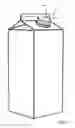
FIG. 1 is a perspective view of a sealed package, which is obtained by using a sonotrode in accordance with the present invention;
FIGS. 2 to 6 shows respective subsequent steps of an operative cycle of a sealing unit comprising the sonotrode in accordance with the present invention;
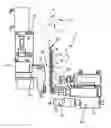
FIG. 7 is an enlarged view the step of FIG. 6;
FIG. 8 is a further enlarged view of FIGS. 6 and 7; and
FIGS. 9 and 10 show further components of the sealing unit of FIGS. 2 to 6, with parts removed for clarity.
DETAILED DESCRIPTION OF PREFERRED EMBODIMENTS
Number 1 in FIGS. 2 to 6 indicates as a whole a unit for applying a plurality of opening devices 4, 4a onto respective open sleeves 6 destined to from respective packages 2.
In greater detail, each opening device 4, 4a is applied onto a hole 3 (FIGS. 7 and 8) made in a packaging material 5 of respective package 2.
Packaging material 5 is made of a heat-seal sheet material, which comprises a layer of paper material covered on both sides with layers of heat-seal plastic material, e.g. polyethylene. In the case of an aseptic package 2 for long-storage products, such as UHT milk, the packaging material comprises a layer of oxygen-barrier material, e.g. aluminium foil, which is superimposed on one or more layers of heat-seal plastic material eventually forming the inner face of package 2 contacting the food product.
Packages 2 preferably contain a pour-able food product, such as pasteurized or UHT milk, fruit juice, wine, etc.
Before the application of opening device 4, 4a, packaging material 5 is cut into blanks. The blanks are firstly erected to form sleeves 6 (FIGS. 4 to 6) which are sealed at their bottom ends (not-shown), while top ends 7 are still open and with hole 3 (FIGS. 7 and 8) still open.
After the application of opening devices 4, 4a, sleeves 6 are filled with the pourable product through their open top ends 7, and respective top ends 7 are sealed, so as to complete the formation of corresponding packages 2.
In the embodiment shown, opening device 4, 4a (FIGS. 7 and 8) has an axis A and substantially comprises:
-
- a flange 8, and
- a neck 9 protruding from flange 8 along an axis A; and
- a cap 10 screwed on neck 9.
In particular, the diameter of flange 8 is larger than the diameter of neck 9.
Opening device 4 is preferably made of polyethylene.
The diameter of hole 3 is smaller than the diameter of flange 8 and larger than the diameter of neck 9.
Once applied by unit 1, flange 8 (FIGS. 7 and 8) contacts a side 5a of packaging material 5, neck 9 passes through hole 3 and cap 10 is arranged on a side 5b, opposite to side 5a, of packaging material 5.
Side 5a of packaging material 5 defines the inner side of package 2 and sleeve 6 whereas side 5b defines the outer side of package 2 and sleeve 6.
Unit 1 comprises (FIGS. 2 to 6 and 9, 10):
-
- a bin (not-shown) which contains opening devices 4, 4a;
- a feeding device 25, which is fed with opening devices 4, 4a and which forms a plurality of columns 24, two in the embodiment shown, of opening devices 4, 4a to be applied on respective sleeves 6;
- a frame 26, which supports a plurality, two in the embodiment shown, of anvils 27;
- a frame 30, which supports a plurality, two in the embodiment shown, of sonotrodes 81; and
- a further feeding device 40 (only partially shown in FIGS. 4 to 6) for advancing packages 2 towards anvils 27 and sonotrodes 81 before the application of opening devices 4, 4a, and for moving away package 2 to which opening device 4, 4a have been applied from anvils 27 and sonotrodes 81 after the application of opening devices 4, 4a.
With reference to FIGS. 2 to 8 it possible to define:
-
- a direction Y, which is vertical in the embodiment shown;
- a direction X, which is orthogonal to direction Y and horizontal in the embodiment shown; and
- a direction Z, which is orthogonal to directions X, Y.
In the embodiment shown, column 24 extends parallel to direction Y.
Frame 26 is arranged on one side of feeding device 25 and sonotrode 81 is arranged below feeding device 25.
In greater detail, feeding device 25 comprises, for each column 24,
-
- a chute 36 elongated parallel to direction Y and vertical in the embodiment shown; and
- an expelling device 37, which is movable parallel to direction X towards and away from relative anvil 27.
Each chute 36 comprises a frame, which is shaped in such a way that the lowermost opening device 4a of each column 24 faces, on one side and along direction X, a relative expelling device 37 along direction X.
Furthermore, the frame of each chute 36 is shaped, so as to firmly contain the other opening devices 4 of respective column 24 along directions X, Z and to allow the fall, under the gravity action, of opening devices 4 along direction Y.
Each expelling device 37 comprises a piston 38 which is movable parallel to direction X between a withdrawn position (FIGS. 2 and 4 to 6) and an extended position (FIG. 3), in which it thrusts the lowermost opening device 4a on the opposite side of frame 26 and towards a respective anvil 27.
Feeding device 40 reciprocates parallel to direction Y between:
-
- a rest position (not-shown), in which sleeves 6 are detached from unit 1; and
- an application position (shown in FIGS. 4 to 7), in which feeding device 40 feeds anvils 2 and sonotrodes 81 with sleeves 6 (only one shown), which have open respective top ends 7 and to which opening devices 4, 4a must still have been applied at respective holes 3.
In the embodiment shown, the rest position is a lowered position along direction Y and the application position in a raised position along direction Y.
Anvils 27 are movable with respect to frame 26 along directions X, Y.
Each anvil 27 is, in particular, movable with respect to frame 26 parallel to direction X, between:
-
- a rest position (FIGS. 2 and 4), in which anvil 27 is outside relative sleeve 6, and is spaced along direction X from relative chute 36 and corresponding lowermost opening device 4a; and
- a loading position (FIG. 3), in which anvil 27 is adjacent to chute 36 and receives the lowermost opening device 4a by respective expelling device 37 set in the extended position.
Furthermore, each anvil 27 is movable with respect to frame 26 parallel to direction Y and through top end 7 of respective sleeve 6 between:
Each anvil 27 is movable with respect to frame 26 and parallel to direction X between:
-
- the intermediate position; and
- an operative position (FIGS. 6 to 8), in which anvil 27 is inside relative sleeve 6 and places opening device 4a inside hole 3.
Frame 26 comprises a carrier 31, which is movable along direction Y onto a guide of frame 26.
In particular, each anvil 27 comprises:
-
- an arm 28, L-shaped in the embodiment shown, which is movable with respect to carrier 31 parallel to direction X; and
- a receiving element 29, which is carried by arm 28 and is adapted to grip, by suction action in the embodiment shown, the lowermost opening device 4a of respective column 24 and to transfer it along directions X, Y with respect to frame 26.
In particular, when each anvil 27 (FIG. 3) is in the rest position, an axis of receiving element 29 is aligned, along direction Y with axis A of lowermost opening device 4a of respective column 24, and on the opposite side, along direction X, with an axis of piston 38 of expelling device 37.
Furthermore, the movement of each anvil 27 from the respective rest position to the respective loading position (and vice-versa) is synchronized with the movement of piston 38 of corresponding feeding device 37 between the respective withdrawn position and the respective extended position (and vice-versa).
In particular, when each anvil 27 (FIG. 5) is in the respective loading position, respective receiving element 29 receives lowermost opening device 4a of respective column 24 from piston 38—set in the extended position—of respective expelling device 37.
Differently, when each anvil 27 (FIG. 4) is in the respective rest position, respective receiving element 29 is spaced along direction X from axis A of the lowermost opening device 4a and piston 38, which is set in the withdrawn position.
Each sonotrode 81 is movable parallel to direction X and relative to frame 30 between:
-
- a rest position (FIGS. 2 to 5), in which it is spaced apart from sleeve 7; and
- an operative position (FIGS. 6 and 7), in which it receives a respective lowermost opening device 4a from receiving element 29 of corresponding anvil 27 and is operated to seal opening device 4a—which engages hole 3—to packaging material 3 of respective sleeve 6 at hole 2.
in particular, the movement of each anvil 27 parallel to direction Y, X and of corresponding sonotrode 81 parallel to direction X is synchronized with the movement of feeding device 40 parallel to direction Y.
Still more precisely, when each anvil 27 moves from the respective rest position to the respective loading position (and vice-versa) and from the respective rest position to the respective intermediate position, respective sonotrode 81 is in the respective rest position and feeding device 40 is in the rest position.
Afterwards, each anvil 27 and relative sonotrode 81 reach respective operative positions simultaneously and when feeding device 40 is in the application position (FIGS. 6 to 8).
In this configuration, each anvil 27 exerts a counter-pressure on flange 8 of relative opening device 4a inserted inside hole 3, during the sealing of opening device 4a to packaging material 5 surrounding hole 3 of relative sleeve 6.
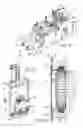
In greater detail, each sonotrode 81 comprises (FIGS. 7 to 9):
-
- a body 84;
- a head 86 opposite to body 84 with respect to direction Y and extending about an axis B parallel to direction Y; and
- a connection 87 interposed between head 86 and body 84.
With reference to FIGS. 8 and 9, head 86 defines, on the opposite side of body 84 and towards side 5b of packaging material 5, a sealing surface 89 and an opening 88.
Each sealing surface 89 contacts, when relative sonotrode 81 and corresponding anvil 27 are in the respective operative positions, side 5b of packaging material 5 so as to seal it on flange 8 of respective opening device 4a.
Sonotrode 81 comprises a cavity 90 that extends about axis B, which coincides with axis A when opening device 4a is inserted in cavity 90.
Head 86 is connected, according to a known solution, to a drive unit (not shown).
Drive unit of sonotrode 81 is formed by a stack of alternate piezoelectric ceramic plates and conductive metal sheets and is coupled to an alternate current generator. In this way, the piezoelectric ceramic plates convert the electric power supplied by the alternate current generator into a mechanical strain, which causes the oscillation of head 86 and, therefore, the sealing of flange 8 to side 5a of packaging material 5 surrounding hole 3 of relative sleeve 6.
Cavity 90 receives opening device 4, when the latter is inserted in hole 3 by receiving element 29 of relative anvil 27.
In particular, cavity 90 is bounded by a wall 92 annularly with respect to axis B and by opening 88 axially with respect to axis B and on the side of surface 89.
Advantageously, sonotrode 81 comprises a ring 91 made in elastomeric material, partially protruding inside cavity 90 and adapted to center axis A of opening device 4a on axis B of sonotrode 81.
In greater detail, ring 91 is fitted to wall 92 and protrudes inside cavity 90 from wall 92.
In particular, wall 92 and neck 9 of opening device 4 are separated, radially to axis B by a gap 100 (FIGS. 7 and 8).
Gap 100 is bounded axially between opening 89 and ring 91.
Ring 91 is radially bounded, on the side of axis B, by a wall 95 which tapers, proceeding from opening 88 towards the opposite side of side 3b of web 3, when ring 91 is not deformed.
In particular, wall 95 converges towards axis B, proceeding from opening 88 towards the opposite side of surface 89.
Ring 91 cooperates with cap 10 of opening device 4 and is adapted to center opening device 4 with respect to head 86.
When ring 91 of each sonotrode 81 is deformed (see FIG. 8), wall 95 defines, proceeding from opening 88 towards the opposite side of side 5b of packaging material 5 surrounding hole 3:
-
- a portion 93 angled at a first angle with respect to axis B; and
- a portion 94 angled at a second angle smaller than first angle with respect to axis B.
Ring 91 is, in the embodiment shown, made of elastomeric material, preferably a thermosetting material.
Still more preferably, ring 91 is made of cellular polyurethane elastomer commercially known as cellasto.
Ring 91 is, therefore, effective to center axis A of opening device 4, 4a with respect to axis B of opening 88 of sonotrode 81, without transferring the ultrasonic vibration to cap 10.
The operation of unit 1 is hereinafter described, with reference to only one anvil 27, only one corresponding sonotrode 81, only one corresponding opening device 4a and only one corresponding sleeve 6 and package 2.
Furthermore, the operation of unit 1 is hereinafter described starting from a condition, in which anvil 27 and sonotrode 81 are in the respective rest positions and feeding device 40 is in the rest position, as shown in FIG. 2.
Starting from this condition, piston 38 of expelling device 37 is moved parallel to direction X and towards the extended position, while anvil 27 moves parallel to direction X and towards chute 36 (i.e. on the right side in FIG. 3) from the rest position to the loading position.
As a result, the lowermost opening device 4a is displaced from chute 36 inside receiving element 29 of anvil 27, which grips it by vacuum action, in the embodiment shown.
At this point, anvil 27 moves back parallel to direction X towards frame 26 up to reach again the rest position (FIG. 4), while feeding device 40 reaches the application position and feeds sonotrode 81 and anvil 27 with sleeve 6 with open top end 7.
At this stage (FIG. 5), anvil 27 moves parallel to direction Y, downwards in the embodiment shown, in the intermediate position. As it moves parallel to direction Y, anvil 27 passes through open top end 7 of sleeve 6 and reaches a position along direction Y, in which receiving element 29 is aligned along direction X with axis of hole 3.
Afterwards (FIG. 6), anvil 27 moves parallel to direction Y and towards hole 3—i.e. on the right side in FIG. 6—from the intermediate position to the operative position, while sonotrode 81 moves parallel to direction X from the rest position to the operative position.
When both anvil 27 and sonotrode 81 are in the respective operative positions (FIGS. 6 to 8), opening device 4a engages hole 3 and is partly housed inside cavity 90 of sonotrode 81.
Still more precisely, when both anvil 27 and sonotrode 81 are in the respective operative positions, neck 9 and cap 10 of opening device 4 enter cavity 90, cap 10 cooperates with wall 95 of ring 91, flange 8 contacts side 5a of packaging material 5 around hole 3 and sealing surface 89 contacts side 5a of packaging material 5 of package 2 (FIG. 9).
Furthermore, cap 10 deforms wall 92 of ring 91, so as to create portion 93, 94 (FIG. 9) differently angled with respect to axis B of head 86 of sonotrode 81.
In this way, ring 91 effectively centers axis A of opening device 4 with axis B of head 86.
Finally, when neck 9 and cap 10 of opening device 4 are housed inside cavity 90 of sonotrode 81, gap 100 is created between wall 92 and cap 10 (FIGS. 7 and 8).
At this stage, sonotrode 81 is activated and head 86 oscillates, so as to seal opening device 4 to packaging material 5 of sleeve 6 around hole 3.
Once the sealing has been completed, sonotrode 81 and anvil 27 come back in respective rest position, and feeding device 40 come back in the rest position.
Subsequently, in a not shown way, top end 7 of sleeve 6—to which opening device 4a has been applied—is sealed, so as to complete the formation of package 2.
At this stage, sonotrode 81 comes back in the rest position along direction X, anvil 27 comes back in the intermediate position along direction X and in the rest position along direction Y, and the cycle re-starts again.
The advantages of unit 1 according to the present invention will be clear from the foregoing description.
In particular, ring 91 made in elastomeric material is efficient in centering opening devices 4a inside cavities 90 of respective sonotrodes 81, without transferring the ultrasonic vibration to caps 10 and, therefore, without affecting the sealing of opening devices 4a onto the packaging material 5 surrounding hole 3.
Ring 91 is conical and tapers on the opposite side of opening 88 and surface 89.
In this way, the contact area between rings 91 and relative caps 10 is particularly small.
Finally, thanks to the presence of gap 100, only surface 89 of sonotrode 81 contacts opening device 4a. Accordingly, thanks to the presence of gap 100 the mechanical oscillation of sonotrode 81 is transferred correctly to flange 8 of opening device 4a with no useless transfer to neck 7 and cap 10 of opening device 4a.
Clearly, changes may be made to sonotrode 81 without, however, departing from the protective scope defined in the accompanying Claims.
In particular, sonotrode 81 could be used for applying a pre-formed opening device 4 onto a web of packaging material which will be folded into a tube, transversally heat-sealed and transversally cut so as to form a plurality of sealed packages.
Claims
1. A sonotrode for sealing an opening device onto a hole of a packaging material destined to from a sealed package, comprising:
a sealing surface adapted to cooperate with a said packaging material in order to seal said opening device to said packaging material;
a cavity bounded by an opening of said sealing surface and adapted to receive said opening device;
characterized by comprising:
a ring made in elastomeric material, partially protruding inside said cavity, and adapted to center a first axis of said opening device on a second axis of said sonotrode.
2. The sonotrode of claim 1, wherein said ring comprises, on the side of said second axis, a wall which tapers on the opposite side of said opening and is adapted to contact said opening device.
3. The sonotrode of claim 1, wherein said ring contacts, in use, a portion (9, 10) of said opening device; said sealing surface contacting, in use, a flange (8) of said opening device from which said portion (9, 10) protrudes.
4. The sonotrode of claim 3, wherein said wall comprises, at least when said ring contacts, in use, said opening device and is elastically deformed by said opening device, proceeding from said opening towards the opposite side to said opening:
a first portion (93) angled at a first angle with respect to said axis; and
a second portion (94) angled at a second angle with respect to said axis.
5. The sonotrode of claim 4, wherein said second angle is smaller than said first angle.
6. The sonotrode of claim 1, wherein said opening bounds said cavity.
7. The sonotrode of claim 1, comprising a further wall, which bounds said cavity and from which said ring radially protrudes, so as to create, in use, a gap between said further wall and said opening device.
8. The sonotrode of claim 1, wherein said elastomeric material is a thermosetting material, preferably a cellular polyurethane elastomer.
9. A unit for applying at least one opening device onto an open sleeve destined to form a sealed package, comprising:
a sonotrode according to claim 1; and
an anvil, which is adapted to co-operate with said opening device, on the opposite side of said sonotrode, during the sealing of said opening device to said packaging material of said sleeve.
10. The unit of claim 9, wherein said anvil is movable through a second opening defined by said sleeve between:
a rest position; and
an operative position, in which cooperates with said opening device, during said sealing of said opening device to said packaging material of said sleeve.
11. The unit of claim 10, wherein said second opening is sealed after the application of said opening device onto said sleeve, so as to form said sealed package.
Images & Drawings included:


Sources:
- United States Patent and Trademark Office - verify current appl. status at the USPTO↗
Recent applications in this class:
- » 20250289187 2025-09-18
ULTRASONIC WELDING AND SNAP-FITTING STRUCTURE AND ULTRASONIC WELDED HOUSING - » 20250269609 2025-08-28
SEALING AND CUTTING DEVICE FOR FORMING FILTER-BAGS WITH INFUSION PRODUCTS - » 20250249643 2025-08-07
ULTRASOUND PROBE HANDLE - » 20250249642 2025-08-07
COMPLIANT CONSOLIDATION BLOCK FOR CONTINUOUS WELDING OF POLYMER MATRIX COMPOSITES - » 20250222659 2025-07-10
WELDING THERMOPLASTIC COMPOSITE AND HONEYCOMB CORE - » 20250058528 2025-02-20
BELT MOLDING MANUFACTURING METHOD - » 20250050591 2025-02-13
ULTRASOUND THREAD WELDING - » 20250026082 2025-01-23
ULTRASONIC WELDING OF AN INSULATING RECEPTACLE - » 20240424742 2024-12-26
SEAM CONSTRUCTION USING RADIO FREQUENCY WELDING AND TAPE - » 20240391179 2024-11-28
ULTRASONIC WELDING THERMOPLASTIC MATERIAL USING ENERGY TRANSMISSION MATERIAL
Recent applications for this Assignee:
- » 20250282520 2025-09-11
OPENING DEVICE FOR A PACKAGE AND PACKAGE THEREWITH - » 20250276298 2025-09-04
A VALVE, A MIXING UNIT AND A METHOD FOR MIXING A LIQUID FOOD PRODUCT WITH A POWDER FOOD PRODUCT - » 20250275563 2025-09-04
A METHOD AND A MIXER FOR COOKING A FOOD PRODUCT THAT CONTAINS STARCH - » 20250269996 2025-08-28
PACKAGING BLANK, METHOD FOR MOLDING A LID-SPOUT ASSEMBLY ONTO A PACKAGING BLANK, LID SPOUT ASSEMBLY, PACKAGE HAVING A LID-SPOUT ASSEMBLY AND METHOD AND APPARATUS FOR FORMING A PACKAGING BLANK - » 20250256885 2025-08-14
OPENING DEVICE FOR A PACKAGE AND PACKAGE THEREWITH - » 20250256879 2025-08-14
VIRTUAL SENSING SYSTEM FOR CONDITION MONITORING OF A CONTAINER PACKAGING MACHINE - » 20250256467 2025-08-14
A METHOD FOR ASSESSING A SEALING OF A CARTON PACKAGE AND AN APPARATUS THEREOF - » 20250250057 2025-08-07
PACKAGING BLANK AND PACKAGE - » 20250214122 2025-07-03
A CLEANING IN PLACE UNIT, A CLEANING IN PLACE SYSTEM AND A METHOD THEREOF - » 20250206005 2025-06-26
A LAMINATED PACKAGING MATERIAL AND PACKAGING CONTAINER MANUFACTURED THEREFROM