Projected neutral bend axis hinge
US20170208699A1
2017-07-20
15/407,245
2017-01-16
✅ Patent granted
US 10,459,482 B2
2019-10-29
-
-
William L Miller
2037-10-14
Abstract:
A method and apparatus for folding a case along a hinge where the hinge is designed to project the neutral bend access of the fold to a layer affixed to an outer surface of the case.
Applicant:
Interested in similar patents?
Get notified when new applications in this technology area are published.
Classification:
H05K5/0226 » CPC main
Casings, cabinets or drawers for electric apparatus; Details; Mechanical details of casings Hinges
H05K5/0226 » CPC main
Casings, cabinets or drawers for electric apparatus; Details; Mechanical details of casings Hinges
E05Y2900/606 » CPC further
Application of doors, windows, wings or fittings thereof for other use for electronic devices
H05K5/0017 » CPC further
Casings, cabinets or drawers for electric apparatus with operator interface units
H05K5/0017 » CPC further
Casings, cabinets or drawers for electric apparatus with operator interface units
H05K5/02 IPC
Casings, cabinets or drawers for electric apparatus Details
H05K5/02 IPC
Casings, cabinets or drawers for electric apparatus Details
E05D3/06 » CPC further
Hinges with pins with two or more pins
F16C11/04 » CPC further
Pivots; Pivotal connections Pivotal connections
E05D7/00 » CPC further
Hinges or pivots of special construction
G06F1/1616 » CPC main
Details not covered by groups - and; Constructional details or arrangements for portable computers with several enclosures having relative motions, each enclosure supporting at least one I/O or computing function with folding flat displays, e.g. laptop computers or notebooks having a clamshell configuration, with body parts pivoting to an open position around an axis parallel to the plane they define in closed position
G06F1/1652 » CPC further
Details not covered by groups - and; Constructional details or arrangements for portable computers; Constructional details or arrangements of portable computers not specific to the type of enclosures covered by groups - ; Details related to the display arrangement, including those related to the mounting of the display in the housing the display being flexible, e.g. mimicking a sheet of paper, or rollable
G06F1/1681 » CPC further
Details not covered by groups - and; Constructional details or arrangements for portable computers; Constructional details or arrangements of portable computers not specific to the type of enclosures covered by groups - ; Miscellaneous details related to the relative movement between the different enclosures or enclosure parts Details related solely to hinges
G09F9/301 » CPC further
Indicating arrangements for variable information in which the information is built-up on a support by selection or combination of individual elements in which the desired character or characters are formed by combining individual elements flexible foldable or roll-able electronic displays, e.g. thin LCD, OLED
H04M1/0216 » CPC further
Substation equipment, e.g. for use by subscribers; Constructional features of telephone sets; Portable telephone sets, e.g. cordless phones, mobile phones or bar type handsets; Portable telephones comprising a plurality of mechanically joined movable body parts, e.g. hinged housings characterized by the relative motions of the body parts; Foldable telephones, i.e. with body parts pivoting to an open position around an axis parallel to the plane they define in closed position Foldable in one direction, i.e. using a one degree of freedom hinge
H04M1/0268 » CPC further
Substation equipment, e.g. for use by subscribers; Constructional features of telephone sets; Portable telephone sets, e.g. cordless phones, mobile phones or bar type handsets; Details of the structure or mounting of specific components for a display module assembly including a flexible display panel
Y10T16/5475 » CPC further
Miscellaneous hardware [e.g., bushing, carpet fastener, caster, door closer, panel hanger, attachable or adjunct handle, hinge, window sash balance, etc.]; Hinge having plural hinge axes [e.g., multiple pintle]; Connected by serially arranged pivoted links between hinged members Plural sets of serially arranged pivoted links
G06F1/16 IPC
Details not covered by groups - and Constructional details or arrangements
G09F9/30 IPC
Indicating arrangements for variable information in which the information is built-up on a support by selection or combination of individual elements in which the desired character or characters are formed by combining individual elements
H04M1/02 IPC
Substation equipment, e.g. for use by subscribers Constructional features of telephone sets
Description
CROSS REFERENCE TO RELATED APPLICATIONS
This non-provisional application claims priority to U.S. provisional application 62/279,476 filed on Jan. 15, 2016, which is incorporated herein by reference.
BACKGROUND OF THE INVENTION
1. Field of the Invention
This invention relates to a method for folding an electronic device with a flexible display where the device case hinges such that the display experiences neither a tension nor compression force when the device is folded.
2. Statement of the Problem
It is convenient to be able to fold a mobile electronic device. Folding a tablet sized device, for example, would allow it to fit in a user's pocket. Folding displays are becoming possible with the advent of OLED displays processed on thin flexible substrates. These displays, however, are complex laminates comprised of numerous materials with varying elasticities. So, though they can bend, they are not easily compressed and stretched. When a laminate is bent, there is a neutral bend axis where the material experiences neither a compression nor a tension stress. The material outside this axis experiences tension stresses while the material inside this axis experiences compression stresses. It is preferable for this neutral bend axis be reserved for the layer in the display least able to withstand these stresses.
It is often desirable for the display on a mobile device to be mounted to a case that can act as a base for the display and contain electronics, batteries, and the like. To be able to fold the device, the case will require a hinge. Traditional hinges contain the neutral bend axis, thus causing tension or compression stress in the display mounted to the case as the device is folded.
SUMMARY OF THE SOLUTION
The present invention solves the above and other problems with a hinge that is able to project the neutral bend axis to a location above or below it.
Aspects
An aspect of the invention is how the hinge is comprised of two hinge layers where each hinge layer is comprised of two or more segments connected end to end with pivots pins, and where each hinge layer contains the same number segments, and where each segment in the first hinge layer is paired with a segment in the second hinge layer, and where the center point of the pared segments are tied together, and where the length of the segments on the first layer can be varied and the length of the segments in the second hinge layer can be varied.
Another aspect of the invention is how the hinge lays flat when the lengths of the segments in the first hinge layer are equal to the length of the segments in the second hinge layer.
Another aspect of the invention is how the hinge curls towards the first hinge layer when the length of the segments in the first hinge layer are less than the length of the segments in the second hinge layer. Likewise, the hinge curls towards the second hinge layer when the length of the segments in the first hinge layer are greater than the lengths of the segments in the second hinge layer.
Another aspect of the invention is how the length of an arc swept by the hinge can be increased and decreased by proportionately increasing and decreasing the lengths of the segments in the first and second hinge layers.
Another aspect of the invention is how the degrees of the bend formed by the hinge can be increased and decreased by increasing and decreasing the lengths of the segments in one hinge layer with respect to the lengths of the segments in the other hinge layer.
Another aspect of the invention is how the lengths of the segments in the first hinge layer and the lengths of the segments in the second hinge layer can be varied to cause the hinge to open and close while keeping the neutral bend axis a set distance from the pivot points connecting the segments in the first hinge layer.
Another aspect of the invention is how each hinge segment is comprised of a pair of cross ties where the length of the segment is varied by varying the angle between the cross ties, and where adjacent cross ties within each hinge layer can be tied together so the lengths of the segments within a hinge layer remain equal as they increase and decrease.
Alternatively, each hinge segment is comprised of a pair of parallel plates where the length of the segment is varied by sliding the plates relative to one another.
Another aspect of the invention is how a device can be comprised of any number of case pieces (n) connected by (n−1) hinges
DESCRIPTION OF THE DRAWINGS
The above and other advantages and features of the invention may be better understood from a reading of the detailed description taken in conjunction with the drawings. The same reference number represents the same element on all drawings.
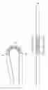
FIG. 1A is a side view of a bi-folding device where the neutral bend axis is inside the hinge. FIG. 1B is a side view of a bi-folding device when the hinge is lying flat. FIG. 1C is a side view of a bi-folding device where the neutral bend axis is outside the hinge.
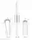
FIG. 2A is a top view of the cross tie assembly between two adjacent pairs of pivots when the bi-folding device is folded so the neutral bend axis is inside the hinge. FIG. 2B is a top view of the cross tie assembly between two adjacent pairs of pivots when the bi-folding device is lying flat. FIG. 2C is a top view of the cross tie assembly between two adjacent pairs of pivots when the bi-folding device is folded so the neutral bend axis is outside the hinge.
FIG. 3A is a simplified side view of two adjacent pairs of pivots where the neutral bend axis is outside the hinge. FIG. 3B is a simplified side view of two adjacent pairs of pivots where the neutral bend axis is inside the hinge.
FIG. 4A is a simplified top view of the cross ties when the bi-folding device is folded so the neutral bend axis is inside the hinge. FIG. 4B is a simplified top view of the cross ties when the bi-folding device is lying flat. FIG. 4C is a simplified top view of the cross ties when the bi-folding device is folded so the neutral bend axis is outside the hinge.
DETAILED DESCRIPTION OF THE INVENTION
FIGS. 1-4 and the following description depict specific exemplary embodiments of the invention to teach those skilled in the art how to make and use the best mode of the invention. For the purpose of teaching inventive principles, some conventional aspects of the invention have been simplified or omitted. Those skilled in the art will appreciate variations from these embodiments that fall within the scope of the invention. Those skilled in the art will appreciate that the features described below can be combined in various ways to form multiple variations of the invention. As a result, the invention is not limited to the specific embodiments described below, but only by the claims and their equivalents.
FIG. 1 shows three folding configurations of device 100: in FIG. 1A device 100 is folded with the neutral bend axis is inside the hinge, in FIG. 1B device 100 is folded with the neutral bend axis beside the hinge, and in FIG. 1C device 100 is folded with the neutral bend axis outside the hinge.
The bi-folding device 100 consists of a display laminate 107 covering two case enclosure pieces 101 and 106 connected by two hinge layers where each layer is comprised of five link segments each. Each link segment within the first hinge layer is paired with a link segment in the second hinge layer. For example, link segment 110 is paired with link segment 120. The link segments are constructed in a manner that allows them to expand and contract. In a preferred embodiment, all the link segments within the first hinge layer are the same length and all the segments within the second hinge layer are the same length.
The link segments within a hinge layer are connected to one another and the case pieces at pivot pins. For example, link segment 110 is connected to link segment 112 via pivot pin 111. These pivot pins allow the segments to rotate relative to one another.
The paired link segments between hinge layers are tied together at the links' center points.
The ability of the links to expand and contract combined with their ability to rotate, allow the hinge to open and close while keeping display 107 on the neutral bend axis.
FIG. 2 shows the top and end views of a link represented by link pair 114/124. It shows the details of the mechanism in three different states. FIG. 2A shows the mechanism where the neutral bend axis would be inside the hinge. FIG. 2B shows the mechanism where the neutral bend axis would be beside the hinge. FIG. 2C shows the mechanism where the neutral bend axis would be outside the hinge.
In this embodiment, each link pair is implemented as a single link mechanism 200. Link mechanism 200 consists of two cross ties 201 and 203 connected at pivot point 202, and eight sleeves that connect it to four pivot pins. The cross tie is connected to each pivot pin via two sleeves. The geometry of the link mechanism allows the distance between the pivot pins in each hinge layer to expand and contract where the relationship of first layer distance to the second layer distance follows a deterministic function.
FIG. 3A shows a representation of link pair 114/124 when the neutral bend axis is outside the hinge. FIG. 3A shows a representation of link pair 114/124 when the neutral ben axis is outside the hinge. As can be derived from these diagrams, if
-
- Θ is the total angle of the case bend divided by the number of segment pairs,
- h is the fixed distance between paired pivot pins,
- d is a defined gap between the hinge mechanism and the neutral bend axis,
- a is the length of the arc swept out over the link segment,
- r is the radius of the arc,
- l1 is the distance between the pivot pin pairs on hinge layer 1, and
- l2 is the distance between the pivot pin pairs on hinge layer 2, then
l1=2·(r−d)·sin(Θ/2) and
l2=2·(r−d−h)·sin(Θ/2) for FIG. 3A
l1=2·(r+d)·sin(Θ/2) and
l2=2·(r+d+h)·sin(Θ/2) for FIG. 3B
a/2πr=Θ/2π
Along the neutral bend axis there is no stretching or compressing so “a” is held constant. Thus “r” will vary as “Θ” varies. Rearranging and substituting yields:
l1=2·(a/Θ−d)·sin(Θ/2) and
l2=2·(a/Θ−d−h)·sin(Θ/2) for FIG. 3A
l1=2·(a/Θ+d)·sin(Θ/2) and
l2=2·(a/Θ+d+h)·sin(Θ/2) for FIG. 3B
FIG. 4 shows a representation of link pair 114/124 in various states. As can be derived from these diagrams:
l1=2·r1·sin θ2
l2=2·r2·sin(θ2+θΔ)
where r1, r2, and ΘΔ are fixed based on the design of the cross tie.
The table of calculations below show a design example where carefully selected values for “do”, “r1”, and “r2” based on given design specifications will keep the display on the neutral bend axis as the case is folded by varying θ2.
| Design Specifications |
| Minimum bend radius | 7.500 | mm |
| Maximum bend angle | 190.000° | |
| Number of links | 5 |
| Distance between paired | 2.400 | mm | |
| pivots (h) | |||
| Distance from hinge to | 1.700 | mm | |
| inside neutral bend | |||
| axis (di) |
| Selected Values |
| Distance from hinge | 1.535 | mm | |
| to outside neutral | |||
| bend axis (do) | |||
| Cross tie radius to hinge | 5.000 | mm | |
| layer 1 (r1) | |||
| Cross tie radius to hinge | 11.058 | mm | |
| layer 2 (r2) |
| Calculated Values |
| Arc length (a) (calculate | 4.974 | mm | |
| when Φ = maximum | |||
| bend angle) |
| Cross tie angle delta (θΔ) | 16.832° | |
| (calculate when Φ = 0 | ||
| Total | ||||||||
| Bend | Target | Target | Actual | Actual | d error | |||
| Angle° | Φ° | 11 mm | 12 mm | θ1° | θ2° | 11 mm | 12 mm | mm |
| −190 | −38 | 3.884 | 2.322 | 22.857 | 6.026 | 3.884 | 2.322 | 0.000 |
| −180 | −36 | 3.944 | 2.461 | 23.231 | 6.399 | 3.944 | 2.465 | 0.005 |
| −170 | −34 | 4.004 | 2.601 | 23.605 | 6.773 | 4.004 | 2.608 | 0.010 |
| −160 | −32 | 4.064 | 2.741 | 23.978 | 7.146 | 4.064 | 2.751 | 0.014 |
| −150 | −30 | 4.123 | 2.881 | 24.351 | 7.519 | 4.123 | 2.894 | 0.019 |
| −140 | −28 | 4.182 | 3.021 | 24.723 | 7.892 | 4.182 | 3.037 | 0.023 |
| −130 | −26 | 4.241 | 3.161 | 25.095 | 8.264 | 4.241 | 3.179 | 0.028 |
| −120 | −24 | 4.300 | 3.302 | 25.466 | 8.635 | 4.300 | 3.320 | 0.032 |
| −110 | −22 | 4.358 | 3.442 | 25.837 | 9.005 | 4.358 | 3.462 | 0.037 |
| −100 | −20 | 4.416 | 3.583 | 26.206 | 9.375 | 4.416 | 3.602 | 0.041 |
| −90 | −18 | 4.474 | 3.723 | 26.575 | 9.743 | 4.474 | 3.743 | 0.046 |
| −80 | −16 | 4.531 | 3.863 | 26.942 | 10.111 | 4.531 | 3.882 | 0.050 |
| −70 | −14 | 4.588 | 4.003 | 27.308 | 10.477 | 4.588 | 4.022 | 0.054 |
| −60 | −12 | 4.644 | 4.143 | 27.673 | 10.842 | 4.644 | 4.160 | 0.058 |
| −50 | −10 | 4.700 | 4.282 | 28.037 | 11.205 | 4.700 | 4.298 | 0.062 |
| −40 | −8 | 4.756 | 4.421 | 28.399 | 11.567 | 4.756 | 4.435 | 0.066 |
| −30 | −6 | 4.811 | 4.560 | 28.759 | 11.928 | 4.811 | 4.571 | 0.071 |
| −20 | −4 | 4.866 | 4.699 | 29.118 | 12.286 | 4.866 | 4.706 | 0.075 |
| −10 | −2 | 4.920 | 4.837 | 29.475 | 12.643 | 4.920 | 4.841 | 0.079 |
| 0 | 0 | 4.974 | 4.974 | 29.829 | 12.998 | 4.974 | 4.974 | 0.000 |
| 10 | 2 | 5.033 | 5.117 | 30.220 | 13.389 | 5.033 | 5.121 | 0.078 |
| 20 | 4 | 5.092 | 5.259 | 30.609 | 13.778 | 5.092 | 5.267 | 0.074 |
| 30 | 6 | 5.150 | 5.401 | 30.997 | 14.165 | 5.150 | 5.412 | 0.070 |
| 40 | 8 | 5.207 | 5.542 | 31.381 | 14.550 | 5.207 | 5.556 | 0.065 |
| 50 | 10 | 5.264 | 5.683 | 31.764 | 14.932 | 5.264 | 5.699 | 0.061 |
| 60 | 12 | 5.320 | 5.822 | 32.144 | 15.312 | 5.320 | 5.840 | 0.056 |
| 70 | 14 | 5.376 | 5.961 | 32.522 | 15.690 | 5.376 | 5.981 | 0.052 |
| 80 | 16 | 5.431 | 6.099 | 32.896 | 16.065 | 5.431 | 6.120 | 0.048 |
| 90 | 18 | 5.486 | 6.237 | 33.269 | 16.437 | 5.486 | 6.258 | 0.043 |
| 100 | 20 | 5.539 | 6.373 | 33.638 | 16.806 | 5.539 | 6.394 | 0.039 |
| 110 | 22 | 5.592 | 6.508 | 34.004 | 17.172 | 5.592 | 6.530 | 0.035 |
| 120 | 24 | 5.645 | 6.643 | 34.366 | 17.535 | 5.645 | 6.663 | 0.030 |
| 130 | 26 | 5.696 | 6.776 | 34.725 | 17.894 | 5.696 | 6.795 | 0.026 |
| 140 | 28 | 5.747 | 6.909 | 35.081 | 18.250 | 5.747 | 6.926 | 0.022 |
| 150 | 30 | 5.798 | 7.040 | 35.433 | 18.602 | 5.798 | 7.055 | 0.017 |
| 160 | 32 | 5.847 | 7.170 | 35.781 | 18.950 | 5.847 | 7.182 | 0.013 |
| 170 | 34 | 5.896 | 7.299 | 36.126 | 19.294 | 5.896 | 7.308 | 0.009 |
| 180 | 36 | 5.943 | 7.427 | 36.466 | 19.634 | 5.943 | 7.431 | 0.004 |
| 190 | 38 | 5.990 | 7.553 | 36.802 | 19.970 | 5.990 | 7.553 | 0.000 |
The error shown in the last column is easily accommodated by an elastomer layer that fills the gap and smooths the discontinuities between the hinge mechanism and the display laminate. Because this elastomer is not on the neutral bend axis, it is selected based on its Poisson ratio to match the reduction in the gap from “di” when the elastomer is compressed, to “do” when the elastomer is stretched.
Although specific embodiments were described herein, the scope of the invention is not limited to those specific embodiments. The scope of the invention is defined by the following claims and any equivalents therein.
Claims
I claim:1. A method for folding a device along a hinge connecting two case pieces that projects the neutral bend axis to a flexible layer mounted on an outer surface of the case pieces.
2. The method of claim 1 where the neutral bend axis is inside the hinge.
3. The method of claim 1 where the neutral bend axis is outside the hinge.
4. The method of claim 1 where the hinge is comprised of two hinge layers where each hinge layer is comprised of two or more link segments, and where each hinge layer contains the same number of link segments, and where each segment in the first hinge layer is paired with a link segment in the second hinge layer, and where the relative location of the center points of paired link segments is held constant, and where the lengths of the link segments in the first hinge layer can be varied and the length of the link segments in the second hinge layer can be varied.
5. The method of claim 4 where the hinge lays flat when the length of the link segments in the first hinge layer are equal to the length of the link segments in the second hinge layer.
6. The method of claim 4 where the hinge curls towards the first hinge layer when the length of the link segments in the first hinge layer are less than the length of the link segments in the second hinge layer.
7. The method of claim 4 where the hinge curls towards the second hinge layer when the length of the link segments in the first hinge layer are greater than the length of the link segments in the second hinge layer.
8. The method of claim 4 where the length of an arc swept by the hinge can be increased and decreased by increasing and decreasing the length of the link segments in the first and second hinge layers by a proportional amount.
9. The method of claim 4 where the length of the link segments in the first hinge layer and the length of the link segments in the second hinge layer can be varied to cause the hinge to open and close while keeping the neutral bend axis a set distance from the pivot pins in the first hinge layer.
10. The method of claim 4 where a link segment is comprised of cross ties where the length of the link segment is varied by varying the angle between the cross ties.
11. The method of claim 10 where the cross ties of paired link segments on the two hinge layers share a common pivot point and have a fixed relationship determined so the length of the link segments in the first hinge layer and the length of the segments on the second hinge layer are varied as the hinge opens and closes to keep the neutral bend axis a fixed distance from the pivot pins on the first hinge layer.
12. The method of claim 10 where the cross ties of paired link segments on the two hinge layers share a common pivot point but operate independently of one another, and where individual stepper motors are controlled to cause the hinge to bend while keeping the neutral bend axis a fixed distance from the pivot pins on the first hinge layer.
13. The method of claim 4 where a link segment is comprised of parallel plates where the length of the link segment is varied by sliding the plates in and out.
14. An apparatus that folds along a hinge connecting two case pieces that projects the neutral bend axis to a flexible layer mounted on an outer surface of the case pieces.
15. The apparatus in claim 14 where the neutral bend axis is inside the hinge.
16. The apparatus in claim 14 where the neutral bend axis is outside the hinge.
17. The apparatus in claim 14 where the hinge is comprised of two hinge layers where each hinge layer is comprised of two or more link segments, and where each hinge layer contains the same number of link segments, and where each link segment in the first hinge layer is paired with a link segment in the second hinge layer, and where the relative location of the center points of paired link segments is held constant, and where the length of the link segments in the first hinge layer can be varied and the length of the link segments in the second hinge layer can be varied.
18. The apparatus of claim 17 where the hinge lays flat when the length of the link segments in the first hinge layer are equal to the length of the link segments in the second hinge layer.
19. The apparatus of claim 17 where the hinge curls towards the first hinge layer when the length of the link segments in the first hinge layer are less than the length of the link segments in the second hinge layer.
20. The apparatus of claim 17 where the hinge curls towards the second hinge layer when the length of the link segments in the first hinge layer are greater than the lengths of the link segments in the second hinge layer.
21. The apparatus of claim 17 where the length of an arc swept by the hinge can be increased and decreased by increasing and decreasing the length of the link segments in the first and second hinge layers by a proportional amount.
22. The apparatus of claim 17 where the length of the link segments in the first hinge layer and the length of the link segments in the second hinge layer can be varied to cause the hinge to open and close while keeping the neutral bend axis a set distance from the pivot pins in the first hinge layer.
23. The apparatus of claim 17 where all link segments are comprised of cross ties where the length of a link segment is varied by varying the angle between the cross ties.
24. The apparatus of claim 23 where the cross ties of paired link segments on the two hinge layers share a common pivot point and have a fixed relationship determined so the length of the link segments in the first hinge layer and the length of the segments in the second hinge layer are varied as the hinge opens and closes to keep the neutral bend axis a fixed distance from the pivot pins on the first hinge layer.
25. The apparatus of claim 23 where the cross ties of paired link segments on the two hinge layers share a common pivot point but operate independently of one another, and where individual stepper motors are controlled to cause the hinge to bend while keeping the neutral bend axis a fixed distance from the pivot pins on the first hinge layer.
26. The apparatus of claim 17 where a link segment is comprised of two plates where the length of the link segment is varied by sliding the plates in and out.
Images & Drawings included:


Sources:
- United States Patent and Trademark Office - verify current appl. status at the USPTO↗
Recent applications in this class:
- » 20250294691 2025-09-18
CONSOLE DISPLAY HINGE SYSTEM - » 20250275073 2025-08-28
Hinge Mechanism and Electronic Device - » 20250267807 2025-08-21
HINGE OF FLEXIBLE SCREEN MOBILE TERMINAL - » 20250261320 2025-08-14
ELECTRONIC DEVICE - » 20250254806 2025-08-07
GLASS ARTICLE FOR VEHICLE INTERIOR SYSTEM HAVING A BENDABLE DISPLAY UNIT - » 20250254805 2025-08-07
FOLDABLE ELECTRONIC DEVICE - » 20250247976 2025-07-31
HINGE, DISPLAY PANEL, AND ELECTRONIC DEVICE - » 20250240902 2025-07-24
ELECTRONIC DEVICE COMPRISING HINGE APPARATUS - » 20250240901 2025-07-24
HINGE ASSEMBLY AND ELECTRONIC DEVICE INCLUDING THE SAME - » 20250220833 2025-07-03
SLIDING MECHANISM AND ELECTRONIC DEVICE