Orthogonal electrical connector penetrator system for coiled tubing electrical service in a flow-through multi-bowled wellhead and method of installation and use
US20170211339A1
2017-07-27
15/326,897
2015-07-17
✅ Patent granted
US 10,745,976 B2
2020-08-18
WO; PCT/US2015/040864; 20150717
WO; WO2016/011326; 20160121
Robert E Fuller | Theodore N Yao
MH2 TECHNOLOGY LAW GROUP LLP
2036-03-16
Abstract:
An electrical interconnect system which allows electrical service to be provided to an ESP suspended on coiled tubing without exiting the wellhead at the top of the well head structure, with three aligned plugs into which is inserted an exterior plug providing each leg of the electrical service to the ESP within the well.
Inventors:
- Tod D. Emerson 5 🇺🇸 Magnolia, TX, United States
- Jim WILLIAMS 2 🇺🇸 Montgomery, TX, United States
- J. Patrick PAYNE 1 🇺🇸 League City, TX, United States
Assignee:
- Quick Connectors, Inc. 13 🇺🇸 Houston, TX, United States
Applicant:
Interested in similar patents?
Get notified when new applications in this technology area are published.
Classification:
E21B17/023 » CPC further
Drilling rods or pipes; Flexible drill strings; Kellies; Drill collars; Sucker rods; Casings Cables; ; Tubings; Couplings; joints Arrangements for connecting cables or wirelines to downhole devices
E21B17/025 » CPC further
Drilling rods or pipes; Flexible drill strings; Kellies; Drill collars; Sucker rods; Casings Cables; ; Tubings; Couplings; joints; Arrangements for connecting cables or wirelines to downhole devices Side entry subs
E21B33/0385 » CPC further
Sealing or packing boreholes or wells; Surface sealing or packing; Well heads; Setting-up thereof specially adapted for underwater installations; Connectors used on well heads, e.g. for connecting blow-out preventer and riser electrical connectors
E21B33/03 IPC
Sealing or packing boreholes or wells; Surface sealing or packing Well heads; Setting-up thereof
E21B33/038 IPC
Sealing or packing boreholes or wells; Surface sealing or packing; Well heads; Setting-up thereof specially adapted for underwater installations Connectors used on well heads, e.g. for connecting blow-out preventer and riser
H02K3/30 » CPC further
Details of windings Windings characterised by the insulating material
E21B17/206 » CPC further
Drilling rods or pipes; Flexible drill strings; Kellies; Drill collars; Sucker rods; Casings Cables; ; Tubings; Flexible or articulated drilling pipes, e.g. flexible or articulated rods, pipes or cables with conductors, e.g. electrical, optical
E21B17/028 » CPC main
Drilling rods or pipes; Flexible drill strings; Kellies; Drill collars; Sucker rods; Casings Cables; ; Tubings; Couplings; joints Electrical or electro-magnetic connections
E21B43/128 » CPC further
Methods or apparatus for obtaining oil, gas, water, soluble or meltable materials or a slurry of minerals from wells; Methods or apparatus for controlling the flow of the obtained fluid to or in wells; Lifting well fluids Adaptation of pump systems with down-hole electric drives
H01R24/28 » CPC further
Two-part coupling devices, or either of their cooperating parts, characterised by their overall structure Coupling parts carrying pins, blades or analogous contacts and secured only to wire or cable
H01R43/005 » CPC further
Apparatus or processes specially adapted for manufacturing, assembling, maintaining, or repairing of line connectors or current collectors or for joining electric conductors for making dustproof, splashproof, drip-proof, waterproof, or flameproof connection, coupling, or casing
H01R2105/00 » CPC further
Three poles
E21B17/02 IPC
Drilling rods or pipes; Flexible drill strings; Kellies; Drill collars; Sucker rods; Casings Cables; ; Tubings Couplings; joints
E21B17/20 IPC
Drilling rods or pipes; Flexible drill strings; Kellies; Drill collars; Sucker rods; Casings Cables; ; Tubings Flexible or articulated drilling pipes, e.g. flexible or articulated rods, pipes or cables
E21B43/12 IPC
Methods or apparatus for obtaining oil, gas, water, soluble or meltable materials or a slurry of minerals from wells Methods or apparatus for controlling the flow of the obtained fluid to or in wells
H01R43/00 IPC
Apparatus or processes specially adapted for manufacturing, assembling, maintaining, or repairing of line connectors or current collectors or for joining electric conductors
H01R13/52 » CPC further
Details of coupling devices of the kinds covered by groups or -; Bases; Cases Dustproof, splashproof, drip-proof, waterproof, or flameproof cases
Description
BACKGROUND OF INVENTION
The present invention relates to an electrical connector penetrator system for use in an oil well serviced by a electrical submersible pump (ESP) connected to a coiled tubing string having an ESP power cable retained in the coiled tubing; and, more specifically, to an electrical connector penetrator system exits the wellhead at a right angle, or orthogonally, to the longitudinal bore of the well, while the produced fluid exits the wellhead through a conventional vertical “Christmas” tree, thereby providing a continuous connection from a coiled tubing retained in a hanger containing the electrical conductors providing power to the ESP.
It is highly desirable to provide electrical power through a coiled tubing system attached to an ESP and to provide such an electrical connector penetrator system through an annulus of a production tubing without using the vertical space above a production wellhead tree. This would allow a coiled tubing injector to be placed over the wellhead and to allow insertion and removal of the ESP connected to a coiled tubing in a live well, without having to kill the well to remove the wellhead and electrical cable supplying the ESP.
Accordingly, Applicant designed and implemented an electrical connector mounted on a coiled tubing hanger arrangement sealing the coiled tubing, which is then set in a coiled tubing hanger, inside a bowl of a flow-through wellhead.
SUMMARY OF INVENTION
This orthogonal electrical connector system comprises an electrical conductor seal mandrel adapted to attach to a ESP power cable providing at least three conductors through a coiled tubing; a non-conductive connector sleeve enclosing the at least three electrical conductors providing at least three spaced ports permitting the at least three conductors to connect to an interior electrical plug inserted at right angles within the connector sleeve; and, an exterior plug inserted through a wellhead mating with each of the at least three spaced electrical interior plugs in the connector sleeve. The orthogonal electrical connector system can be arranged to provide the at least three spaced ports positioned vertically within the connector sleeve or positioned horizontally within the connector sleeve.
The at least three conductors extend through the seal mandrel sealed with epoxy surrounding each conductor within the seal mandrel.
The orthogonal electrical connector system can also provide non-conductive connector sleeve aligned within the wellhead to assure alignment of the at least three spaced ports through which the electrical connection is made from the exterior of the flow-through wellhead.
A method for installing an orthogonal electrical connector system on coiled tubing connected to an ESP, retained in a coiled tubing hanger assembly, comprises the steps of rough-cutting an armored cable extending from the coiled tubing to an appropriate length; inserting the armored cable in a mini-mandrel collar and into a mini-mandrel; cutting the armor and stripping the secondary insulation or insulation protection (typically the lead jacket) from a plurality of conductors within the armored jacket without removing the insulation on each conductor; inserting each conductor into a steel tube pressed into a non-ferromagnetic seal body; inserting an elastomeric seal around each steel tube leaving a space between the non-ferromagnetic seal body and the elastomeric seal; filling all interior spaces of the mini-mandrel with epoxy; and, retaining the mini-mandrel in the mini-mandrel collar and thread the collar to the coiled tubing hanger assembly retaining the mini-mandrel on an interior shoulder of the mini-mandrel collar and permitting the electrical conductors to extend there-through.
This method can further comprise the steps of combining one or more PEEK disks providing an opening vertically aligned in a spaced relationship; inserting in each vertically aligned disk an electrical connector attached thereto; attaching a length of electrical conductor to each spaced electrical connector extending through an interior passage to a proximal end of the arrangement; connecting each electrical conductor to a socket permitting connection of the electrical conductors extending from the mini-mandrel; and attaching the PEEK mandrel body comprised of the PEEK disks to the mini-mandrel cap with set screws on a circumferential surface of the mandrel body.
DETAILED DESCRIPTION OF THE DRAWINGS
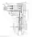
FIG. 1 is a composite drawing of the entire assembly of the orthogonal electrical connector system for coiled tubing electrical service in a flow-through wellhead.
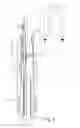
FIG. 2 is a cross-sectional view of electrical conductor mini-mandrel.
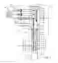
FIG. 3 is a cross-sectional view of the electrical conductor mini-mandrel installed within the mandrel collar connected to a coiled tubing hanger assembly and sealed within the mandrel collar by a mandrel cap through which the electrical conductors are carried and showing the groove around an upper end of said cap into which set screws from the PEEK mandrel are seated.
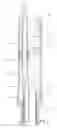
FIG. 4 is a cross-sectional view of the PEEK mandrel showing the vertical alignment ports through the mandrel attached to the mini-mandrel collar threaded on the mini-mandrel collar then threaded together to the slip connection.
DETAILED DESCRIPTION OF AN EMBODIMENT OF THE INVENTION
FIG. 1 is a partial cross-sectional drawing of the entire wellhead assembly including the orthogonal electrical penetrator assembly. The flow-through multi-bowled wellhead 30 consists of at least two aligned portions or bowls providing a number of flow-through passages (not shown) communicating with the well below, and an inner casing 50 for hanging and manipulation of a coiled tubing attached to the wellhead. Each of these two bowls 30 and 50 provides at least three alignable ports 540 permitting an orthogonal electrical connection to be made to the ESP. Each alignable port 540 provides means for insertion of an elastomeric covered electrical connector 535 providing a male pin which can be stabbed into an orthogonal pin connector 560, 560a and 560b seated within a PEEK cable manifold 222, 242 and 262. Each of the bowls 30 and 50 are aligned to allow these three pins to be inserted within the exterior plug 530 found on each pin, although only one complete assembly is shown in FIG. 1. To permit alignment of each of the pins with the orthogonal pin connector 560, 560a and 560b, a void or port 540 is created around each pin and, upon installation, this void or port 540 is filled with a dielectric grease such as DC 104 or DC 111. The electrical conductors are inserted through metallic tubes 520 which are then locked into place on the exterior surface of the wellhead by compression fitting 510 threaded into external plug 530 that is connected to flex-tubing 500 extending from the wellhead surface of bowl 30 to a junction box (not shown) to provide power to the ESP within the well. Each port or void 540 is sealed by an external plug 530 enclosing the aligned orthogonal pin connectors 560, 560a, and 560b.
Each of the orthogonal connectors 560, 560a and 560b is housed within the PEEK cable manifold 222, 242 and 262. The stackable cable splice manifolds and sleeve of this embodiment 200, 222, 242, 262 forming the mandrel 282 could be molded from a single piece of PEEK.
FIG. 4, a view of the assembly without the cross-sectional view of the wellhead, provides a cross-sectional view of the PEEK mandrel 282 showing the vertical alignment ports 220, 220a and 220b through the mandrel 282 attached to the threaded sleeve 87 threaded on the mandrel sleeve 85 and threaded together 86 to the slip connection 82. Each of the vertically spaced and aligned ports 220, 220a and 220b are approximately two (2) inches apart which provides sufficient dielectric strength to prevent shorting of one connection with an adjacent connection during use. In this embodiment, the PEEK mandrel is segmented into stackable cable manifolds 222, 242, and 262. Each of these trays is held together by cap headed screw 400 threaded into internal threads 409 in the base PEEK cable splice sleeve 200. The head 440 of the cap head screw engages the cable manifold 262 to compressively maintain the PEEK mandrel as a unit after installation. The screw 400 provides insulation 410 within each PEEK tray to prevent a pathway for leaking of current during operation. The cable manifold 262 provides a key 281 to align the entire PEEK mandrel body 282 after installation. During installation, each passage would be packed with dielectric grease such as DC 4 or DC 111 to avoid further communication with these connectors.
As next shown in FIG. 2, a quantity of epoxy 95 covers each of the conductors 112 from their exit from the armored cable 100 and shield 105 adjacent an elastomeric seal cup 120 slipped over the stainless steel tubing covering each insulated conductor 112. A second quantity of epoxy 95a is installed between the elastomeric seal cup and the tri-hooter or non-ferromagnetic conductor 150. Additional quantities of epoxy 95b can be put in the distal end of the mini-mandrel to completely fill the mini-mandrel and support the electrical conductors extending from the mini-mandrel into a PEEK cable splice sleeve 200 providing a plurality of ports 220 for connecting electrical plugs from the outer periphery of a flow-through wellhead.
As shown more completely in FIG. 3, a coiled tubing 80 supporting an ESP power cable 100 is hung in a system of slips (not shown) and slip connection 82 within a wellbore allowing a portion of the ESP power cable 100 to extend out of the coiled tubing 80. A portion of the power cable 100 is then removed and the individual electrical conductors 112 are exposed. Each conductor retains its protective dielectric covering 110 made from EPDM and extends through the non-conductive, protective mini-mandrel 90 permitting the electrical conductors to be fed through a plurality of steel tubes 125 which are inserted in an elastomeric seal 120 then press fitted into a tri-hooter or non-ferromagnetic cap 150 retained within the mini-mandrel 90 at an interior shoulder. Each electrical conductor is thus sealed within the seal mini-mandrel 90 on which, at a lower end, O-rings 91 are installed to seal on an interior surface of the mandrel sleeve 85.
The mini-mandrel 90 is installed within the mandrel sleeve 85 which is threaded into or otherwise connected to the coiled tubing hanger system 82 supporting the coiled tubing 80 in slips (not shown) and providing support for the armored cable 100 constrained within said coiled tubing 80. Electrical conductors 112 pass through the mini-mandrel 90 with each remaining protected by the insulation 110. Each electrical conductor 112 is stripped at its distal end and an electrically conductive male plug 114 is attached with set screws 116.
The installation of the mini-mandrel 90 is readily accomplished. The coiled tubing 80 is secured in slips (not shown) within the wellhead. The armored power cable 100 extends from the top of the coiled tubing 80 and is rough-cut to a fixed distance above the end of the coiled tubing slips. A packing sleeve 84 is then slipped over the power cable 100 and shouldered against coil tubing 80. The mandrel sleeve 85 is slipped over the armored cable and the electrical conductors 112, covered by their insulation 110 are threaded through and sealed within the mini-mandrel 90. The mini-mandrel 90 is compressed to shoulder against packing sleeve 84 and then the mandrel sleeve 85 is threaded into the interior threads of the coiled tubing slip 82. After the electrical conductors 112 are stripped and the male electrical conductive plugs 114 are installed of each of the conductors, the mini-mandrel cap 87 is threaded on the exterior threads of the mandrel sleeve 85 sealing the lower portion of the assembly and providing the groove 88 for the set screws 210 on the circumferential lower end of the PEEK cable splice sleeve 200 to be affixed after insertion of each of the conductors in their respective electrical pin connectors within the PEEK mandrel.
FIG. 4 provides a cross-sectional view of the PEEK mandrel 282 showing the vertical alignment ports 220, 220a and 220b through the mandrel 282 attached to the mini-mandrel collar 87 threaded on the mandrel sleeve 85 and threaded together to the slip connection 82 all as previously described. Mandrel cap 202 provides a seat between the mini-mandrel collar 87 and cable splice sleeve 200.
Alternatively, the PEEK mandrel 282 can be molded as one piece with electrical connector sockets installed in the mandrel to allow insertion of the orthogonal male plugs through the aligned wellhead ports to the interior of the wellhead.
Continuing the discussion of the structure shown in FIG. 1, FIG. 4 provides more detail. In this embodiment, the male plug 114 is inserted in a crimp socket 115 from which another section of insulated cable is inserted in an orthogonal electrical connector 560, 560a and 560b disposed in segmented PEEK disks providing indented trays 321, 322, and 323. Similar connections are made with the remaining conductors (not shown) and each orthogonal connector cavity 220, 220a and 220b is thus spaced vertically allowing a male plug to be inserted through an aligned wellhead to connect each of the orthogonal plugs to an exterior surface of the flow-through wellhead (not shown in this view). As each orthogonal plug is completed the indented trays are covered by the adjacent PEEK disk. For example, once the makeup for plug 560 is completed, indented tray 321 is covered by the PEEK cable splice sleeve 200. Likewise when electrical connector 560a is completed, indented tray 322 is covered by PEEK cable manifold 222. Finally, when the last electrical connector is completed in indented tray 323, PEEK cap cable manifold 262 completely seals each electrical orthogonal connector in the PEEK mandrel 282. Each disk is lipped 222a, 242a, 262a to provide an interconnecting unit that can then be sealed together with threaded rods or pins, such as the cap head screw 400 which engages threads 409 in the bottom PEEK mandrel body 282 to provide a rigid interconnecting PEEK mandrel.
Claims
1. An orthogonal electrical connector system comprising:
an electrical conductor seal mandrel (282) adapted to attach to an ESP power cable (100) providing at least three conductors (112) connecting to electrical conductor from a coiled tubing (80);
a non-conductive cable splice sleeve (200) enclosing the at least three electrical conductors (112) providing at least three spaced ports (540) permitting the at least three conductors (220, 220a, 220b) to connect to an interior electrical plug (560, 560a, 560b) inserted at right angles within a cable splice mandrel (282; and,
an exterior plug (530) inserted through a wellhead mating with each of the at least three spaced electrical interior plugs (560, 560a, 560b) in the cable splice sleeve (200).
2. The orthogonal electrical connector system of claim 1 wherein the at least three spaced ports (540) are positioned vertically within the connector sleeve.
3. The orthogonal electrical connector system of claim 1 wherein the at least three spaced ports (540) are positioned horizontally within the connector sleeve.
4. The orthogonal electrical connector system of claim 1 wherein the at least three conductors extend through the seal mandrel (282) sealed with epoxy surrounding each conductor within a sleeve mandrel (87) retaining a mini-mandrel (90) within a threaded mandrel sleeve (85) attached to a slip connection (82).
5. The orthogonal electrical connector system of claim 1 wherein non-conductive cable splice sleeve (200) is aligned within the wellhead to assure alignment of the at least three spaced ports (540).
6. A method for installing an orthogonal electrical connector system on coiled tubing connected to an ESP, retained in a coiled tubing hanger assembly, comprising the steps of:
rough-cutting an armored cable extending from the coiled tubing to an appropriate length;
inserting the armored cable in a mini-mandrel collar and into a mini-mandrel;
cutting the armor and stripping the lead jacket from a plurality of conductors within the armored jacket without removing the insulation on each conductor;
inserting each conductor into a steel tube pressed into a non-ferromagnetic seal body;
inserting an elastomeric seal around each steel tube leaving a space between the non-ferromagnetic seal body and the elastomeric seal;
filling all interior spaces of the mini-mandrel with epoxy;
retaining the mini-mandrel in the mini-mandrel collar; and,
threading the collar to the coiled tubing hanger assembly retaining the mini-mandrel on an interior shoulder of the mini-mandrel collar and permitting the electrical conductors to extend there-through.
7. The method of claim 6 further comprising the steps of:
combining one or more PEEK disks providing an opening vertically aligned in a spaced relationship;
inserting in each vertically aligned disk an electrical connector attached thereto;
attaching a length of electrical conductor to each spaced electrical connector extending through an interior passage to a proximal end of the arrangement;
connecting each electrical conductor to an orthogonal electrical socket permitting connection of the electrical conductors extending from the mini-mandrel; and
attaching the PEEK mandrel body comprised of the PEEK disks to the mini-mandrel cap on a circumferential surface of the mandrel body.
Images & Drawings included:

Sources:
- United States Patent and Trademark Office - verify current appl. status at the USPTO↗
Recent applications in this class:
- » 20250263986 2025-08-21
Power Switch Actuator For Downhole Tools - » 20250237113 2025-07-24
FIBER OPTIC ENABLED INTELLIGENT COMPLETION EMPLOYING AN END CONNECTOR - » 20250101813 2025-03-27
DOWNHOLE WET-MATE SYSTEMS AND METHODS USING WET-MATE DEPLOYMENT CARRIER - » 20250092742 2025-03-20
DOWNHOLE ROTARY SLIP RING JOINT TO ALLOW ROTATION OF ASSEMBLIES WITH THREE OR MORE CONTROL LINES - » 20250034952 2025-01-30
Downhole wet-mate systems with offset stinger and methods for deployment and wet-mate connecting by rotation of the offset stinger - » 20240376787 2024-11-14
Well tool pressure compensating system and method - » 20240352805 2024-10-24
PERMANENTLY INSTALLED IN-WELL DRY MATE CONNECTORS WITH SHAPE MEMORY ALLOY TECHNOLOGY - » 20240318511 2024-09-26
WELL SYSTEM INCLUDING A LOWER COMPLETION STRING COUPLED TO A SERVICE STRING, THE SERVICE STRING HAVING ONE OR MORE SENSORS POSITIONED THERE ALONG - » 20240318510 2024-09-26
MULTIPLE USE WET MATE HAVING A FLUID RESERVOIR CONFIGURED TO RECEIVE A VOLUME OF COUPLING FLUID THEREIN - » 20240309708 2024-09-19
ORIENTING ENERGY TRANSFER MECHANISM CONNECTIONS HIGH SIDE IN A WELL
Recent applications for this Assignee:
- » 20210230959 2021-07-29
Disconnectable pressure-preserving electrical connector and method of installation - » 20190178039 2019-06-13
Double seal for tri-lead style packer penetrators and method of installation - » 20180347287 2018-12-06
Simplified packer penetrator and method of installation - » 20160108693 2016-04-21
Disconnectable pressure-preserving electrical connector and method of installation - » 20150207245 2015-07-23
Power cable splice sleeve and method of installation - » 20140110164 2014-04-24
System for continuous electrical well cable feed-through for a wellhead and method of installation - » 20130277067 2013-10-24
Coiled tubing triple-sealed penetrator and method - » 20110165786 2011-07-07
High pressure, high temperature standoff for electrical connector in an underground well - » 20110017510 2011-01-27
Heater cable to pump cable connector and method of installation - » 20100326725 2010-12-30
Segmented decompression resistant cable splice and method of installation