Overspeed protection device of an aircraft engine
US20170211413A1
2017-07-27
15/327,630
2015-07-21
✅ Patent granted
US 10,208,620 B2
2019-02-19
WO; PCT/FR2015/052006; 20150721
WO; WO2016/012713; 20160128
Lorne Meade | James McGlynn
Womble Bond Dickinson (US) LLP
2035-07-21
Abstract:
The invention relates to an overspeed protection device of an aircraft engine
Inventors:
- Stephen Langford 7 🇫🇷 Pau, France
- Rafael SAMSON 2 🇫🇷 Lit Et Mixe, France
- NICOLAS MARTI 8 🇫🇷 BOULOGNE-BILLANCOURT, France
- Michael MONTOYA 2 🇫🇷 Boulogne-Billancourt, France
Assignee:
- SAFRAN HELICOPTER ENGINES 232 🇫🇷 Bordes, France
- SAFRAN ELECTRONICS & DEFENSE Boulogne 223 🇫🇷 Billancourt, France
Applicant:
Interested in similar patents?
Get notified when new applications in this technology area are published.
Classification:
F02C9/28 » CPC further
Controlling gas-turbine plants; Controlling fuel supply in air- breathing jet-propulsion plants; Control of fuel supply Regulating systems responsive to plant or ambient parameters, e.g. temperature, pressure, rotor speed
F02C7/22 » CPC further
Features, components parts, details or accessories, not provided for in, or of interest apart form groups - ; Air intakes for jet-propulsion plants Fuel supply systems
B64D37/32 » CPC further
Arrangements in connection with fuel supply for power plant Safety measures not otherwise provided for, e.g. preventing explosive conditions
F02C9/46 » CPC further
Controlling gas-turbine plants; Controlling fuel supply in air- breathing jet-propulsion plants; Control of fuel supply Emergency fuel control
F05D2270/021 » CPC further
Control; Purpose of the control system to control rotational speed (n) to prevent overspeed
F01D21/02 » CPC main
Shutting-down of machines or engines, e.g. in emergency; Regulating, controlling, or safety means not otherwise provided for Shutting-down responsive to overspeed
F01D21/14 » CPC further
Shutting-down of machines or engines, e.g. in emergency; Regulating, controlling, or safety means not otherwise provided for responsive to other specific conditions
F02C7/232 » CPC further
Features, components parts, details or accessories, not provided for in, or of interest apart form groups - ; Air intakes for jet-propulsion plants; Fuel supply systems Fuel valves ; Draining valves or systems
F02C9/26 » CPC further
Controlling gas-turbine plants; Controlling fuel supply in air- breathing jet-propulsion plants Control of fuel supply
F02C7/26 » CPC further
Features, components parts, details or accessories, not provided for in, or of interest apart form groups - ; Air intakes for jet-propulsion plants Starting; Ignition
F05D2270/091 » CPC further
Control; Purpose of the control system to cope with emergencies in particular sudden load loss
F05D2270/092 » CPC further
Control; Purpose of the control system to cope with emergencies in particular blow-out and relight
F05D2270/095 » CPC further
Control; Purpose of the control system to cope with emergencies by temporary overriding set control limits
F05D2270/304 » CPC further
Control; Control parameters, e.g. input parameters Spool rotational speed
F05D2270/022 » CPC further
Control; Purpose of the control system to control rotational speed (n) to prevent underspeed
F05D2270/09 » CPC further
Control; Purpose of the control system to cope with emergencies
Description
GENERAL TECHNICAL FIELD
The invention relates to powering aircraft engines and relates more particularly to their overspeed protection.
PRIOR ART
In an aircraft engine, excessive rotation speed of a shaft can have serious consequences, specifically and especially causing rotor discs mounted on the shaft to break. Also, such an engine is usually equipped with an overspeed protection device which receives information representative of the rotation speed of an engine shaft and controls cutting, a regulation or else a limitation of engine fuel supply when, for example, this rotation speed exceeds a predetermined threshold or when acceleration, a function of this speed, exceeds a threshold.
The overspeed safety function can be ensured by an electronic overspeed protection unit which controls a servo-valve or any other element configured to cut/regulate/limit the fuel supply of the engine or prevent the engine from entering overspeed.
This electronic unit is usually segregated from the engine control unit (ECU) and is supplied by the onboard network of the aircraft.
A problem with this type of solution is that the overspeed safety function is supplied by the same onboard network as the regulation function, therefore involving a mode common to the ECU implying that a breakdown of one can cause a breakdown of the other.
PRESENTATION OF THE INVENTION
An aim of the invention is to propose a solution which offers a good compromise of independence between the overspeed safety function and the engine control unit, without any need for complexification of supply.
For this purpose, according to a first aspect the invention proposes an overspeed protection device of an aircraft engine comprising a fuel supply system of said rotating machine, the protection device comprising
-
- a voltage source configured to deliver voltage according to negative or positive polarization;
- a logic control device connected in series to the voltage source, said logic control device being configured to open or close the supply system as a function of the polarization of the delivered voltage;
- a first electronic unit connected in series to the voltage source and the logic control device and which comprises
- a first speed sensor delivering a first discrete electric control signal as a function of the speed of the engine;
- a normally closed first switch controlled by said first discrete electric control signal;
- a second electronic unit connected in series to the voltage source and the logic control device and which comprises
- a second speed sensor delivering a second discrete electric control signal as a function of the speed of the engine;
- a normally closed second switch controlled by said second discrete electric control signal;
- the normally closed first switch and the normally closed second switch having a ‘closed’ state letting current pass through and an ‘open’ state letting no current pass through;
- the logic control device being arranged between both the first electronic unit and the second electronic unit;
- the normally closed first and second switches being sensitive respectively to the first and second discrete electric control signals only if the voltage has predetermined polarization, for this predetermined polarization, the first and second switches letting the first and second electronic units isolate or connect the logic control device of the voltage source as a function of said discrete electric control signals.
The invention is advantageously completed by the following optional characteristics, taken singly or in any association of their technically possible combination:
-
- the first and second speed sensors are configured to measure a speed of the engine and deliver discrete electric control signals having a high state for a speed of the engine Vengine such as Vthreshold1≦Vengine<Vthreshold2, with Vthreshold1 a first threshold and Vthreshold2 a second threshold characteristic of overspeed of the aircraft engine; a low state for a speed of the engine such as 0≦Vengine<Vthreshold1 and such as Vengine≧Vthreshold2, or else when the engine has a breakdown;
- the first and second electronic units isolate the logic control device from the voltage source as soon as the first and second switches move from an ‘open’ state to a ‘closed’ state while the logic control device was open, the change of state of said first and second switches causing closing of the servo-valve.
- the first and second speed sensors are configured to provide electric energy from rotation of the engine so as to self-feed said protection device.
- the first and second speed sensors are of inductive type, for example with a phonic wheel, of alternator winding type or else an active electric sensor for measuring speed.
- the device comprises a polarizer mounted in parallel with the voltage source, said polarizer being configured to polarize voltage coming from the voltage source.
- the first and second switches are constituted by a transistor preferably of Darlington or bipolar type.
There are many advantages to the invention.
-
- the simplex architecture shared in two independent functions over two independent housings;
- There is total segregation between the overspeed safety function and the engine control unit;
- Different supply sources coming from the aircraft or the control system between the overspeed safety function and the engine control unit can be used;
- The supply independence dispenses with the fire resistance requirement on the supply function of the control part;
- Breakdown detection is improved since the operating capacity of the device is linked to proper functioning of the sensors.
- The architecture of the device maintains a simplex actuator to prevent the start of overspeed and ensure operating safety requirements, the capacity to actuate the device being tested before each start, with for consequence in case of breakdown the non-start.
The invention also relates to a fuel supply system of an aircraft engine comprising an overspeed protection device according to the first aspect.
The invention further relates to an aircraft engine comprising a supply device according to the first aspect.
PRESENTATION OF THE FIGURES
Other features, aims and advantages of the invention will emerge from the following description which is purely illustrative and non-limiting and which must be considered with respect to the appended drawings, wherein:
FIG. 1 schematically illustrates a protection device according to the invention;
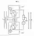
FIG. 2 illustrates an embodiment of a switch of a protection device according to the invention;
FIGS. 3 to 5 illustrate operation of a protection device according to the invention.
In all figures similar elements bear identical references.
DETAILED DESCRIPTION OF THE INVENTION
FIG. 1 illustrates an overspeed protection device of an aircraft engine according to an embodiment of the invention.
The engine (not shown) of the aircraft comprises for example a fuel supply line 10 which can be closed or limited by the protection device. Of course, the protection device applies to any rotating machine comprising a fuel supply device.
Of course the invention described in relation to this embodiment can apply to any means for preventing the engine from starting overspeed (stopping, slowdown, etc.).
The protection device comprises a voltage source S configured to deliver a voltage V according to negative or positive polarization. Therefore the voltage source S is configured to deliver amplitude voltage having for absolute value |V| according to negative or positive polarization. The voltage source therefore delivers supply voltage equal to ±V as a function of the applied polarization.
The protection device comprises a polarizer P which is controlled by a control signal CMD#P originating from an order sent from the aircraft, or by an order sent by a control computer (not shown), on the basis of specific algorithms ensuring toggling of the polarization (not detailed here).
So that the fuel supply line 10 can be opened or closed, by way of non-limiting example the protection device comprises a logic control device such as a servo-valve ECA connected in series to the voltage source S. The servo-valve ECA is controlled as a function of the polarization of the voltage delivered by the voltage source S.
As is known per se, this servo-valve ECA is bistable and therefore comprises two stable states. In fact, it is considered that the servo-valve moves from an ‘open’ state (supply line 10 open) to a ‘closed’ state (supply line 10 closed) as soon as the polarization of the voltage changes to supply the servo-valve ECA according to positive or negative current.
The protection device comprises a first electronic unit ECU#1 connected in series to the voltage source S and the servo-valve ECA, the first electronic unit ECU#1 being downstream of the servo-valve, in the figure.
The first electronic unit ECU#1 comprises a first speed sensor C1 delivering a first discrete electric control signal CMD#1 as a function of the speed of the engine and a normally closed first switch I1 controlled by the first discrete electric control signal CMD#1.
It is specified here that the term speed sensor means an assembly for determining from physical information such as speed a control signal by means of physical information/electric signal conversion stage.
Also, the protection device comprises a second electronic unit ECU#2 connected in series to the voltage source S and the servo-valve ECA, the second electronic unit ECU#2 being upstream of the servo-valve ECA, in the figure.
As will be evident, the servo-valve ECA is arranged both part between the first electronic unit ECU#1 and also the second electronic unit ECU#2.
The second electronic unit ECU#2 comprises a second speed sensor C2 delivering a second discrete electric control signal CMD#2 as a function of the speed of the engine and a normally closed second switch I2 controlled by the second discrete electric control signal CMD#2.
It is considered that a normally closed switch has a ‘closed’ state letting current pass through and an ‘open’ state letting no current pass through.
The first C1 and second C2 speed sensors are configured to measure a speed of the engine and deliver discrete electric control signals presenting:
-
- a high state (‘1’) for a speed of the engine Vengine such as Vthreshold1≦Vengine<Vthreshold2, with Vthreshold1 a first threshold and Vthreshold2 a second threshold characteristic of overspeed;
- a low state (‘0’) for a speed of the engine such as 0≦Vengine<Vthreshold1 and such as Vengine≧Vthreshold2, or else when the engine has a breakdown.
The second threshold is of course higher than the first threshold.
So, for an engine having reached a speed higher than the first threshold (Vthreshold1) the high state ‘1’ corresponds to an absence of breakdown or an absence of overspeed and the low state ‘0’ corresponds to overspeed or breakdown. A typical first threshold Vthreshold1 is for example a speed of the aircraft engine equal to 30% of the cruising speed preferred for the aircraft engine.
However, it is considered that the engine is in overspeed as soon as the speed is greater than or equal to the second threshold typically (Vthreshold2) comprised between 110% and 130%, typically 120% of the cruising speed of the aircraft engine.
Also, the first C1 and second C2 speed sensors measure speed at different points so as to create independence of measurements and having no common mode apart from the rotation of the engine.
This ensures adequate fire resistance and avoids effects of common mode, also routing precautions are carried out to ensure topological segregation for measurements.
These first C1 and second C2 speed sensors are configured to provide from the rotation of the engine electric energy for self-feeding the protection device.
The first and second sensors are of inductive type or, more generally, of the type capable of providing an indication of speed and power. This sensor is used as a source of power and also source of measuring. A type of sensor is for example of a phonic wheel or alternator winding type or else an active electric sensor of angular position “Rotary Variable Differential Transformer”, (RVDT).
In the protection device, the servo-valve ECA is framed by respectively the first electronic unit ECU#1 and the second electronic unit ECU#2 which isolate the servo-valve ECA from the voltage source S under certain conditions.
In fact, the first I1 and second I2 switches of each of the first ECU#1 and second ECU#2 electronic units are sensitive, for single polarization of the voltage, to the first CMD#1 and second CMD#2 discrete electric control signals.
To modify the polarization of the voltage, the protection device comprises a polarizer P which is controlled by a control signal CMD#P which is a function of a state of the aircraft engine: ‘start’, ‘slowed’ (i.e., having started).
It is considered that the first I1 and second I2 switches are sensitive to the first CMD#1 and second CMD#2 discrete electric control signals when the voltage source S delivers voltage at positive polarization i.e., equal to +V.
It is considered also that when the polarization is positive:
-
- The first switch I1 is closed for a first discrete electric control signal CMD#1=‘0’ (low state);
- The first switch I1 is open for a first discrete electric control signal CMD#1=‘1’ (high state);
- The second switch I2 is closed for a second discrete electric control signal CMD#2=‘0’ (low state);
- The second switch I2 is open for a second discrete electric control signal CMD#2=‘1’ (high state).
For this positive polarization, the first ECU#1 and second ECU#2 electronic units close the servo-valve ECA of the voltage source S as soon as the first I1 and second I2 switches move from an ‘open’ state (CMD#1=‘0’, CMD#2=‘0’) to a ‘closed’ state (CMD#1=‘1’, CMD#2=‘1’) and that the servo-valve ECA was open, the change of state of the first I1 and second I2 switches thus causing closing of the servo-valve (ECA).
In this way, it is ensured that the two electric control signals are both in the high state for closing the fuel line 10, avoiding untimely closing of the latter. In fact, when one or the other of the first or second switches is ‘open’ while the other is ‘closed’, the servo-valve ECA cannot be supplied by the voltage source S. This is all the more advantageous since the first ECU#1 and second ECU#2 electronic units are independent because the first C1 and second C2 sensors measure the speed of the aircraft engine independently.
FIG. 2 illustrates a possible electronic circuit of an electronic unit (the first ECU#1 or the second ECU#2) of the protection device described hereinabove.
The normally closed switch (the first I1 or the second I2) comprises a first transistor T1 NPN controlled by the discrete electric control signal CMD#N (N=1 or 2) and a second transistor T2 NPN, the collector of the first transistor T1 is connected to the base of the second transistor T2.
The circuit also comprises a diode D connected between the servo-valve ECA and the voltage source 11, the diode D mounted inversely to the transistor T2.
Also, the circuit comprises a first resistance R1 connected to the base of the first transistor T1, the first resistance R1 applying the electric control signal CMD#N to the base of the first transistor T1.
Also, a second resistance R2 is connected between the base of the second transistor T2 and the collector of the second transistor T2.
By way of advantage, the second transistor T2 is of Darlington type, which has the advantage of polarizing the transistor T2 with very weak current and substantially limiting leakage currents when the transistor T2 is open.
Preferred operation of the protection device described hereinabove is explained below.
In relation to FIG. 3, the state of the aircraft engine is ‘start’. The polarizer P receives a command CMD#P controlling the voltage source so that it delivers voltage having negative polarization equal to V. As will be evident the engine therefore must be supplied with fuel and the normally closed switches I1, I2 not be sensitive to the electric control signals CMD#1, CMD#2 so as to prevent untimely closing of the fuel supply line 10 of the engine which is open in this case. During start, the first and second sensors C1, C2 deliver respectively first and second discrete electric control signals CMD#1, CMD#2 in the low state (CMD#1=‘0’, CMD#2=‘0’). The engine can start. It is noted that in ‘start’ mode, only the state of the diodes counts such that the control device is insensitive to the electric control signals CMD#1, CMD#2.
The aircraft engine then moves to the ‘started’ state. In relation to the ‘start’ state the first C1 and second C2 sensors now deliver first and second discrete electric control signals CMD#1, CMD#2 in the high state (CMD#1=‘1’, CMD#2=‘1’), the speed of the engine being at 30% of its cruising speed. Of course, the servo-valve ECA still keeps the fuel line 10 open to enable fuel supply to the engine. It is from this state that the overspeed protection must be active.
In relation to FIG. 4, the state of the aircraft engine is ‘slowed’, i.e., it has been able to start. In this case the overspeed protection must be active. The first and second discrete electric control signals CMD#1, CMD#2 are in the high state (CMD#1=‘1’, CMD#2=‘1’), and the polarizer P receives a command CMD#P controlling the voltage source S so that it delivers voltage having positive polarization equal to +V. In this case, the first and second switches I1, I2 are sensitive respectively to the electric control signals CMD#1, CMD#2 and move from the ‘closed’ state to ‘open’. In this way the servo-valve is no longer being powered such that the change in polarization of the delivered voltage by the voltage source S has no effect on the latter. The aircraft engine is therefore still being supplied with fuel, the servo-valve ECA now open. Also, the first C1 and second C2 sensors are still delivering first and second discrete electric control signals CMD#1, CMD#2 in the high state (CMD#1 =‘1’, CMD#2=‘1’), the speed of the engine still being greater than 30% of the cruising speed of the engine.
In relation to FIG. 5, the state of the aircraft engine is ‘fault’. A fault is for example a loss of the first and/or second discrete electric control signal CMD#1, CMD#2) or detection of overspeed of the engine. The loss can be due to failure of the engine or else to failure of the first and/or of the second speed sensor(s) C1, C2. Since the protection function is active (the voltage source S delivering voltage having positive polarization and equal to +V), the first and second switches I1, I2 are sensitive respectively to the first and second discrete electric control signals CMD#1, CMD#2. But, given that the first ECU#1 and second ECU#2 electronic unit are on both sides of the servo-valve ECA, to be connected to the voltage source S the two switches I1, I2 have to be in the closed state. In this way it can change state (it was open previously) since the polarization will have changed. In this way, there is closing of the fuel line 10 only when the two electric control signals are in the low state (CMD#1 =‘0’, CMD#2=‘0’). As explained previously, because the states of the electric control signals are independent, the closing of the fuel line 10 is not untimely.
The invention is not limited to the protection device described hereinabove and also relates to a fuel supply system of an aircraft engine comprising a overspeed protection device described hereinabove as well as an aircraft engine comprising such a supply device.
Claims
1. An overspeed protection device of an aircraft engine comprising a fuel supply system of said aircraft engine, the protection device comprising
a voltage source configured to deliver voltage according to negative or positive polarization;
a logic control device connected in series to the voltage source, said logic control device being configured to open or close the supply system as a function of the polarization of the delivered voltage;
a first electronic unit connected in series to the voltage source and the logic control device and which comprises
a first speed sensor delivering a first discrete electric control signal as a function of the speed of the engine;
a normally closed first switch controlled by said first discrete electric control signal;
a second electronic unit connected in series to the voltage source and the logic control device and which comprises
a second speed sensor delivering a second discrete electric control signal as a function of the speed of the engine;
a normally closed second switch controlled by said second discrete electric control signal;
the normally closed first switch and the normally closed second switch having a ‘closed’ state letting current pass through and an ‘open’ state letting no current pass through;
the logic control device being arranged between both the first electronic unit and the second electronic unit;
the normally closed first and second switches being sensitive respectively to the first and second discrete electric control signals only if the voltage has a same predetermined polarization, for this same predetermined polarization, the first and second switches letting the first and second electronic units isolate or connect the logic control device of the voltage source as a function of said discrete electric control signals.
2. The protection device according to claim 1, wherein the first and second speed sensors are configured to measure a speed of the engine and deliver discrete electric control signals having
a high state (‘1’) for a speed of the engine Vengine such as Vthreshold1≦Vengine<Vthreshold2, with Vthreshold1 a first threshold and Vthreshold2 a second threshold characteristic of overspeed;
a low state (‘0’) for a speed of the engine such as 0≦Vengine<Vthreshold1 and such as Vengine≧Vthreshold2, or else when the engine has a breakdown.
3. The protection device according to claim 1, wherein the first and second electronic units isolate the logic control device from the voltage source as soon as the first and second switches move from an ‘open’ state to a ‘closed’ state while the logic control device was open, the change of state of said first and second switches causing closing of the servo-valve.
4. The protection device according to claim 1, wherein the first and second speed sensors are configured to provide electric energy from rotation of the engine so as to self-feed said protection device.
5. The protection device according to claim 4, wherein the first and second speed sensors are of inductive type, for example with a phonic wheel, of alternator winding type or else an active electric sensor for measuring speed.
6. The protection device according to claim 1, comprising a polarizer mounted in parallel with the voltage source, said polarizer being configured to polarize voltage coming from the voltage source.
7. The protection device according to claim 1, wherein the first and second switches are constituted by a transistor preferably of Darlington or bipolar type.
8. A fuel supply system of an aircraft engine comprising an overspeed protection device according to claim 1.
9. An aircraft engine comprising a supply device according to claim 1.
Images & Drawings included:


Sources:
- United States Patent and Trademark Office - verify current appl. status at the USPTO↗
Recent applications in this class:
- » 20250109695 2025-04-03
SYSTEM AND METHOD FOR OVERSPEED DETECTION AND PROTECTION IN AN ENGINE - » 20230407761 2023-12-21
Electronic overspeed protection system and method - » 20220162961 2022-05-26
System and method for rotor overspeed mitigation - » 20210262360 2021-08-26
Overspeed protection for a motor of a gate crossing mechanism - » 20210017880 2021-01-21
Turbine shaft of a turbomachine and method for protecting against overspeed of said shaft - » 20200362723 2020-11-19
System and method for detecting an uncommanded or uncontrollable high thrust event in an aircraft - » 20200248581 2020-08-06
Gas turbine engine shaft break mitigation - » 20190323376 2019-10-24
Dual trip manifold assembly for turbine systems - » 20190277156 2019-09-12
Device for limiting overspeeding of a turbine shaft of a turbomachine, and associated control method - » 20180283203 2018-10-04
Method and system for rotor overspeed protection
Recent applications for this Assignee:
- » 20250215824 2025-07-03
IMPROVED PROPULSION ASSEMBLY FOR MULTI-ENGINE HYBRID AIRCRAFT - » 20250215810 2025-07-03
AIRCRAFT TURBOMACHINE COMPRISING A BEARING SUPPORT HAVING AN IMPROVED DESIGN - » 20250207510 2025-06-26
LUBRICATION AND COOLING OF EQUIPMENT OF AN AIRCRAFT TURBOMACHINE - » 20250188865 2025-06-12
IMPROVED TURBOMACHINE FOR HYBRID AIRCRAFT - » 20250187739 2025-06-12
IMPROVED PROPULSIVE ASSEMBLY FOR A MULTI-ENGINE HYBRID AIRCRAFT - » 20250092833 2025-03-20
TRANSFER OF POWER BETWEEN THE HIGH-PRESSURE SHAFT AND THE LOW-PRESSURE SHAFT OF A TURBOMACHINE - » 20250067211 2025-02-27
Recovered-cycle turboshaft engine - » 20250059918 2025-02-20
AIRCRAFT TURBOMACHINE COMPRISING A DEVICE FOR INHIBITING THE ACCUMULATION OF COKE IN A DUCT - » 20250034680 2025-01-30
METAL POWDER FOR A POWDER BED ADDITIVE MANUFACTURING PROCESS - » 20250027426 2025-01-23
CONTROL DEVICE FOR CONTROLLING AN AIRFLOW GUIDING SYSTEM, IN PARTICULAR IN AN AIRCRAFT TURBINE ENGINE