DIMPLE PATTERNS FOR GOLF BALLS
US20170225040A1
2017-08-10
15/498,043
2017-04-26
Abstract:
The present invention provides dimple patterns with icosahedral tilings where the dimples are arranged in multiple copies of a first domain and a second domain, and the dimple pattern in the first domain is different than the dimple pattern in the second domain. A majority of dimples are provided having a first plan shape and a first profile shape, and at least one of the domains has a sub-pattern of nearest neighbor dimples having either a plan shape or a dimple profile shape that is different than the majority of dimples.
Inventors:
- Nicholas M. Nardacci 157 🇺🇸 Barrington, RI, United States
- Michael R. Madson 184 🇺🇸 Easton, MA, United States
Assignee:
- Acushnet Company 2,454 🇺🇸 Fairhaven, MA, United States
Interested in similar patents?
Get notified when new applications in this technology area are published.
Classification:
A63B37/0006 » CPC main
Solid balls; Marbles Rigid hollow balls;; Golf balls; Surface depressions or protrusions Arrangement or layout of dimples
A63B37/00 IPC
Balls
A63B37/00 IPC
Solid balls; Marbles Rigid hollow balls;
Description
CROSS REFERENCE TO RELATED APPLICATIONS
This application is a Continuation-in-Part of co-pending U.S. patent application Ser. No. 13/672,910, filed Nov. 9, 2012, which is a Continuation-in-Part of U.S. patent application Ser. No. 13/251,590, filed Oct. 3, 2011, now abandoned, which is a Divisional of U.S. patent application Ser. No. 12/262,464 filed Oct. 31, 2008, now U.S. Pat. No. 8,029,388, the disclosures of which are incorporated by reference herein in their entirety.
FIELD OF THE INVENTION
This invention relates to golf balls, particularly to golf balls having improved dimple patterns. More particularly, the invention relates to methods of arranging dimples on a golf ball by generating irregular domains based on polyhedrons, packing the irregular domains with dimples, and tessellating the domains onto the surface of the golf ball. Still more particularly, this invention relates to dimple patterns with icosahedral tilings wherein there exists a sub-pattern of dimples that are additionally tiled around the ball such that the sub-pattern dimples exhibit a different plan shape or dimple profile than the other dimples on the golf ball.
BACKGROUND OF THE INVENTION
Historically, dimple patterns for golf balls have had a variety of geometric shapes, patterns, and configurations. Primarily, patterns are laid out in order to provide desired performance characteristics based on the particular ball construction, material attributes, and player characteristics influencing the ball's initial launch angle and spin conditions. Therefore, pattern development is a secondary design step that is used to achieve the appropriate aerodynamic behavior, thereby tailoring ball flight characteristics and performance.
Aerodynamic forces generated by a ball in flight are a result of its velocity and spin. These forces can be represented by a lift force and a drag force. Lift force is perpendicular to the direction of flight and is a result of air velocity differences above and below the rotating ball. This phenomenon is attributed to Magnus, who described it in 1853 after studying the aerodynamic forces on spinning spheres and cylinders, and is described by Bernoulli's Equation, a simplification of the first law of thermodynamics. Bernoulli's equation relates pressure and velocity where pressure is inversely proportional to the square of velocity. The velocity differential, due to faster moving air on top and slower moving air on the bottom, results in lower air pressure on top and an upward directed force on the ball.
Drag is opposite in sense to the direction of flight and orthogonal to lift. The drag force on a ball is attributed to parasitic drag forces, which consist of pressure drag and viscous or skin friction drag. A sphere is a bluff body, which is an inefficient aerodynamic shape. As a result, the accelerating flow field around the ball causes a large pressure differential with high-pressure forward and low-pressure behind the ball. The low pressure area behind the ball is also known as the wake. In order to minimize pressure drag, dimples provide a means to energize the flow field and delay the separation of flow, or reduce the wake region behind the ball. Skin friction is a viscous effect residing close to the surface of the ball within the boundary layer. The industry has seen many efforts to maximize the aerodynamics of golf balls, through dimple disturbance and other methods, though they are closely controlled by golf's national governing body, the United States Golf Association (U.S.G.A.). One U.S.G.A. requirement is that golf balls have aerodynamic symmetry. Aerodynamic symmetry allows the ball to fly with a very small amount of variation no matter how the golf ball is placed on the tee or ground. Preferably, dimples cover the maximum surface area of the golf ball without detrimentally affecting the aerodynamic symmetry of the golf ball.
In attempts to improve aerodynamic symmetry, many dimple patterns are based on geometric shapes. These may include circles, hexagons, triangles, and the like. Other dimple patterns are based in general on the five Platonic Solids including icosahedron, dodecahedron, octahedron, cube, or tetrahedron. Yet other dimple patterns are based on the thirteen Archimedean Solids, such as the small icosidodecahedron, rhomicosidodecahedron, small rhombicuboctahedron, snub cube, snub dodecahedron, or truncated icosahedron. Furthermore, other dimple patterns are based on hexagonal dipyramids. Because the number of symmetric solid plane systems is limited, it is difficult to devise new symmetric patterns. Moreover, dimple patterns based some of these geometric shapes result in less than optimal surface coverage and other disadvantageous dimple arrangements. Therefore, dimple properties such as number, shape, size, and arrangement are often manipulated in an attempt to generate a golf ball that has better aerodynamic properties.
U.S. Pat. No. 5,562,552 to Thurman discloses a golf ball with an icosahedral dimple pattern, wherein each triangular face of the icosahedron is split by a three straight lines which each bisect a corner of the face to form 3 triangular faces for each icosahedral face, wherein the dimples are arranged consistently on the icosahedral faces.
U.S. Pat. No. 5,046,742 to Mackey discloses a golf ball with dimples packed into a 32-sided polyhedron composed of hexagons and pentagons, wherein the dimple packing is the same in each hexagon and in each pentagon.
U.S. Pat. No. 4,998,733 to Lee discloses a golf ball formed of ten “spherical” hexagons each split into six equilateral triangles, wherein each triangle is split by a bisecting line extending between a vertex of the triangle and the midpoint of the side opposite the vertex, and the bisecting lines are oriented to achieve improved symmetry.
U.S. Pat. No. 6,682,442 to Winfield discloses the use of polygons as packing elements for dimples to introduce predictable variance into the dimple pattern. The polygons extend from the poles of the ball to a parting line. Any space not filled with dimples from the polygons is filled with other dimples. A continuing need exists for a dimple pattern whose dimple arrangement results in a maximized surface coverage and desirable aerodynamic characteristics, including improved symmetry.
SUMMARY OF THE INVENTION
The present invention provides a method for arranging dimples on a golf ball surface that significantly improves aerodynamic symmetry and minimizes parting line visibility by arranging the dimples in a pattern derived from at least one irregular domain generated from a regular or non-regular polyhedron. The method includes choosing control points of a polyhedron, generating an irregular domain based on those control points, packing the irregular domain with dimples, and tessellating the irregular domain to cover the surface of the golf ball.
One embodiment of the present invention provides for an initial dimple sub-pattern contained in the irregular domain(s). The dimple sub-pattern may be defined as nearest neighbor dimples on or within edges of one or more of the irregular domains. Once the sub-pattern is defined, the remaining unpacked spherical region is packed with dimples around the initial sub-pattern of dimples. The irregular domains are then tessellated around the ball surface. The sub-pattern dimples can be packed within any number of the irregular domains.
The method of determining nearest neighbor dimples is illustrated in FIG. 11C, wherein two tangency lines TL are drawn from the center of a first dimple to a potential nearest neighbor dimple. Additionally, a line segment Ls is drawn connecting the center of the first dimple to the center of the potential nearest neighbor dimple. If there is no line segment that is intersected by another dimple, or portion of a dimple, then those dimples are considered to be nearest neighbor dimples.
The golf ball produced by the method of the present invention has a sub-pattern of nearest neighbor dimples that are visually distinct from the other packed dimples. The sub-pattern of nearest neighbor dimples may exhibit different perimeter shape, or dimple profile, or color, or texture, or grooves, or brambles or a combination therein from the packed dimples of the initial base geometry. The sub-pattern of nearest neighbor dimples may have circular perimeters with diameters ranging between 0.100 to 0.220 inches. In golf balls wherein the sub-pattern of nearest neighbor dimples have non-circular perimeters; the diameter range is between 0.120 to 0.270 inches when the non-circular perimeters are circumscribed by a circle.
The present invention provides for a golf ball wherein each sub-pattern contains 2 to 80 nearest neighbor dimples, and wherein the base geometry of each irregular domain contains 10 to 115 dimples. The surface coverage of dimples is between 70 to 90 percent, including surface coverage of sub-pattern nearest neighbor dimples between 10 to 60 percent.
Other embodiments of the present invention may have dimple profiles that are spherical, Gabriel's horn, catenary, conical, Witch of Agnesi, ellipse, or any other profile defined by the superposition of two or more curves or spherically weighted profiles. Further these dimples can have perimeters such as circular, or polygonal, or elliptical.
The present invention is directed to a golf ball having an outer surface and comprising a plurality of dimples disposed thereon. The dimples are arranged in multiple copies of a first domain and a second domain, and the dimple pattern in the first domain is different than the dimple pattern in the second domain. The first domain and the second domain are tessellated to cover the outer surface of the golf ball in a uniform pattern having no great circles and being tessellated in an icosahedron pattern that consists of twenty first domains and twelve second domains.
A majority of dimples have a first plan shape and a first profile shape, and at least one of the domains has a sub-pattern of nearest neighbor dimples having either a plan shape or a dimple profile shape that is different than the majority of dimples.
The first domain has three-way rotational symmetry about a central point of the first domain and the second domain has five-way rotational symmetry about a central point of the second domain.
In one embodiment, the sub-pattern of nearest neighbor dimples are axially symmetric about the central point of one of the two domains. In another embodiment, the sub-pattern of nearest neighbor dimples have a different plan shape than the majority of dimples. For example, the majority of dimples may have a continuous plan shape and the sub-pattern dimples may have a plan shape that is discontinuous.
In another embodiment, the sub-pattern of nearest neighbor dimples have a different dimple plan shape than the majority of dimples. For example, the majority of dimples may have a circular plan shape. It will be appreciated that the sub-pattern of dimples may have a polygonal plan shape, or may have plan shapes based on periodic functions along a path or the sub-pattern of dimples may have plan shapes made of circular arcs derived from polygons.
In yet another embodiment, the sub-pattern of nearest neighbor dimples have a different dimple profile shape than the majority of dimples. For example, the majority of the dimples and the sub-pattern of dimples may be different and chosen from the group of spherical, conical, and catenary, and Gabriel's horn type dimple profiles.
In another embodiment, the majority of dimples may be spherical, while the sub-pattern may be conical or catenary dimples or chosen from the group of circumscribed prismatoids, rotational protrusions, frequency dimples, superposition dimples, Gabriel's horn dimples or grooved dimple profiles.
In yet another embodiment, the sub-pattern of dimples may all be classified as interior dimples within a domain. The interior dimples in one domain may be sub-pattern dimples. In another embodiment, the sub-pattern of dimples may all be classified as perimeter dimples within a domain. The perimeter dimples of one domain may be sub-pattern dimples.
It will be appreciated that in another embodiment, the sub-pattern of dimples may include both interior dimples and perimeter dimples within a domain. The sub-pattern dimples may be classified as perimeter dimples from the first domain and perimeter dimples from the second domain.
At least one sub-pattern dimple may be at the center of one domain, and it will be appreciated that there may be a sub-pattern dimple at the center of both domains.
BRIEF DESCRIPTION OF THE DRAWINGS
In the accompanying drawings which form a part of the specification and are to be read in conjunction therewith and in which like reference numerals are used to indicate like parts in the various views:
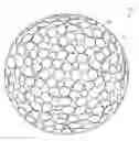
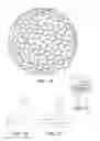
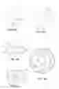
FIG. 1A illustrates a golf ball having dimples arranged by a method of the invention; FIG. 1B illustrates a polyhedron face; FIG. 1C illustrates an element of the invention in the polyhedron face of FIG. 1B; and FIG. 1D illustrates a domain formed by a methods of the invention packed with dimples and formed from two elements of FIG. 1C;
FIG. 2 illustrates a single face of a polyhedron having control points thereon;
FIG. 3A illustrates a polyhedron face; FIG. 3B illustrates an element of the invention packed with dimples; FIG. 3C illustrates a domain of the invention packed with dimples formed from elements of FIG. 3B; and FIG. 3D illustrates a golf ball formed by a method of the invention formed of the domain of FIG. 3C;
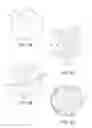
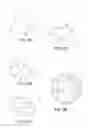
FIG. 4A illustrates two polyhedron faces; FIG. 4B illustrates a first domain of the invention in the two polyhedron faces of FIG. 4A; FIG. 4C illustrates a first domain and a second domain of the invention in three polyhedron faces; FIG. 4D illustrates a golf ball formed by a method of the invention formed of the domains of FIG. 4C;
FIG. 5A illustrates a polyhedron face; FIG. 5B illustrates a first domain of the invention in a polyhedron face; FIG. 5C illustrates a first domain and a second domain of the invention in three polyhedron faces; and FIG. 5D illustrates a golf ball formed using a method of the invention formed of the domains of FIG. 5C;
FIG. 6A illustrates a polyhedron face; FIG. 6B illustrates a portion of a domain of the invention in the polyhedron face of FIG. 6A; FIG. 6C illustrates a domain formed by the methods of the invention; and FIG. 6D illustrates a golf ball formed using the methods of the invention formed of domains of FIG. 6C;
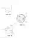
FIG. 7A illustrates a polyhedron face; FIG. 7B illustrates a domain of the invention in the polyhedron face of FIG. 7A; and FIG. 7C illustrates a golf ball formed by a method of the invention;
FIG. 8A illustrates a first element of the invention in a polyhedron face; FIG. 8B illustrates a first and a second element of the invention in the polyhedron face of FIG. 8A; FIG. 8C illustrates two domains of the invention composed of first and second elements of FIG. 8B; FIG. 8D illustrates a single domain of the invention based on the two domains of FIG. 8C; and FIG. 8E illustrates a golf ball formed using a method of the invention formed of the domains of FIG. 8D;
FIG. 9A illustrates a polyhedron face; FIG. 9B illustrates an element of the invention in the polyhedron face of FIG. 9A; FIG. 9C illustrates two elements of FIG. 9B combining to form a domain of the invention; FIG. 9D illustrates a domain formed by the methods of the invention based on the elements of FIG. 9C; and FIG. 9E illustrates a golf ball formed using a method formed of domains of FIG. 9D;
FIG. 10A illustrates a face of a rhombic dodecahedron; FIG. 10B illustrates a segment of the present invention in the face of FIG. 10A; FIG. 10C illustrates the segment of FIG. 10B and copies thereof forming a domain of the present invention; FIG. 10D illustrates a domain formed by a method of the present invention based on the segments of FIG. 10C; and FIG. 10E illustrates a golf ball formed by a method of the present invention formed of domains of FIG. 10D;
FIG. 11A utilizes the mid-point to mid-point tiling method to illustrate irregular domains of the present invention;
FIG. 11B utilizes the mid-point to mid-point tiling method to illustrate irregular domains of the present invention;
FIG. 11C depicts a dimple sub-pattern wherein they are shown as nearest neighbor dimples within edges of one of the irregular domains;
FIG. 11D depicts a dimple sub-pattern wherein they are shown as nearest neighbor dimples within edges of another of the irregular domains;
FIG. 11E shows the domains of FIG. 11C and FIG. 11D tessellated around a golf ball sphere;
FIG. 12A utilizes the mid-point to mid-point tiling method to illustrate irregular domains of the present invention;
FIG. 12B depicts a dimple sub-pattern wherein they are shown as nearest neighbor dimples within edges of one of the irregular domains;
FIG. 12C shows the domains of FIG. 12B tessellated around a golf ball sphere;
FIG. 13A depicts a dimple sub-pattern wherein they are shown as nearest neighbor dimples within edges of one of the irregular domains;
FIG. 13B shows the domains of FIG. 13A tessellated around a golf ball sphere;
FIG. 14A depicts first and second domains of the present invention; FIG. 14B depicts a majority of dimples and sub-pattern dimples in the first and second domains of the present invention; FIG. 14C illustrates a golf ball having the first and second domains of FIG. 14B tessellated on the surface of the golf ball; FIG. 14D depicts the cross-section of the majority of dimples showing the dimple profile; and FIG. 14E depicts the cross-section of the sub-pattern dimples showing the dimple profile;
FIG. 15A depicts first and second domains of the present invention; FIG. 15B depicts a majority of dimples and sub-pattern dimples in the first and second domains of the present invention; FIG. 15C illustrates a golf ball having the first and second domains of FIG. 15B tessellated on the surface of the golf ball; FIG. 15D depicts the cross-section of the majority of dimples showing the dimple profile; and FIG. 15E depicts the cross-section of the sub-pattern dimples showing the dimple profile; and
FIG. 16A depicts first and second domains of an embodiment of the present invention; FIG. 16B depicts a majority of dimples and sub-pattern dimples in the first and second domains of the present invention; FIG. 16C illustrates a golf ball having the first and second domains of FIG. 16B tessellated on the surface of the golf ball; FIG. 16D depicts the plan shape of the majority of dimples; and FIG. 16E depicts the plan shape of the sub-pattern dimples.
DETAILED DESCRIPTION OF THE PREFERRED EMBODIMENTS
The present invention provides a method for arranging dimples on a golf ball surface in a pattern derived from at least one irregular domain generated from a regular or non-regular polyhedron. In the invention as described below extends the method of spherical tiling to include sub-patterns of dimples within the base geometry dimple packing. Unique patterns are thus created with improved aerodynamics and visual aesthetics.
In one embodiment, illustrated in FIG. 1A, the present invention comprises a golf ball 10 comprising dimples 12. Dimples 12 are arranged by packing irregular domains 14 with dimples, as seen best in FIG. 1D. Irregular domains 14 are created in such a way that, when tessellated on the surface of golf ball 10, they impart greater orders of symmetry to the surface than prior art balls. The irregular shape of domains 14 additionally minimize the appearance and effect of the golf ball parting line from the molding process, and allows greater flexibility in arranging dimples than would be available with regularly shaped domains.
The irregular domains can be defined through the use of any one of the exemplary methods described herein. Each method produces one or more unique domains based on circumscribing a sphere with the vertices of a regular polyhedron. The vertices of the circumscribed sphere based on the vertices of the corresponding polyhedron with origin (0,0,0) are defined below in Table 1.
| TABLE 1 |
| Vertices of Circumscribed Sphere based |
| on Corresponding Polyhedron Vertices |
| Type of | |
| Polyhedron | Vertices |
| Tetrahedron | (+1, +1, +1); (−1, −1, +1); (−1, +1, −1); (+1, −1, −1) |
| Cube | (±1, ±1, ±1) |
| Octahedron | (±1, 0, 0); (0, ±1, 0); (0, 0, ±1) |
| Dodecahedron | (±1, ±1, ±1); (0, ±1/φ, ±φ); (±1/φ, ±φ, 0); (±φ, 0, ±1/φ)* |
| Icosahedron | (0, ±1, ±φ); (±1, ±φ, 0); (±φ, 0, ±1)* |
| *φ = (1 + {square root over (5)})/2 |
Each method has a unique set of rules which are followed for the domain to be symmetrically patterned on the surface of the golf ball. Each method is defined by the combination of at least two control points. These control points, which are taken from one or more faces of a regular or non-regular polyhedron, consist of at least three different types: the center C of a polyhedron face; a vertex V of a face of a regular polyhedron; and the midpoint M of an edge of a face of the polyhedron. FIG. 2 shows an exemplary face 16 of a polyhedron (a regular dodecahedron in this case) and one of each a center C, a midpoint M, a vertex V, and an edge E on face 16.
The two control points C, M, or V may be of the same or different types. Accordingly, six types of methods for use with regular polyhedrons are defined as follows:
1. Center to midpoint (C→M);
2. Center to center (C→C);
3. Center to vertex (C→V);
4. Midpoint to midpoint (M→M);
5. Midpoint to Vertex (M→V); and
6. Vertex to Vertex (V→V).
While each method differs in its particulars, they all follow the same basic scheme. First, a non-linear sketch line is drawn connecting the two control points. This sketch line may have any shape, including, but not limited, to an arc, a spline, two or more straight or acute lines or curves, or a combination thereof. Second, the sketch line is patterned in a method specific manner to create a domain, as discussed below. Third, when necessary, the sketch line is patterned in a second fashion to create a second domain.
While the basic scheme is consistent for each of the six methods, each method preferably follows different steps in order to generate the domains from a sketch line between the two control points, as described below with reference to each of the methods individually.
The Center to Vertex Method
Referring again to FIGS. 1A-1D, the center to vertex method yields a domain that tessellates to cover the surface of golf ball 10. The domain is defined as follows:
-
- 1. A regular polyhedron is chosen (FIGS. 1A-1D use an icosahedron);
- 2. A single face 16 of the regular polyhedron is chosen, as shown in FIG. 1B;
- 3. Center C of face 16, and a first vertex V1 of face 16 are connected with any non-linear sketch line, hereinafter referred to as a segment 18;
- 4. A copy 20 of segment 18 is rotated about center C, such that copy 20 connects center C with vertex V2 adjacent to vertex V1. The two segments 18 and 20 and the edge E connecting vertices V1 and V2 define an element 22, as shown best in FIG. 1C; and
- 5. Element 22 is rotated about midpoint M of edge E to create a domain 14, as shown best in FIG. 1D.
When domain 14 is tessellated to cover the surface of golf ball 10, as shown in FIG. 1A, a different number of total domains 14 will result depending on the regular polyhedron chosen as the basis for control points C and V1. The number of domains 14 used to cover the surface of golf ball 10 is equal to the number of faces PF of the polyhedron chosen times the number of edges PE per face of the polyhedron divided by 2, as shown below in Table 2.
TABLE 2: Domains Resulting from Use of Specific Polyhedra when Using the
| TABLE 2 |
| Domains Resulting Form Use of Specific Polyhedra When Using the |
| Center to Vertex Method |
| Type of | Number of Faces, | Number | Number of Domains |
| Polyhedron | PF | of Edges, PE | 14 |
| Tetrahedron | 4 | 3 | 6 |
| Cube | 6 | 4 | 12 |
| Octahedron | 8 | 3 | 12 |
| Dodecahedron | 12 | 5 | 30 |
| Icosahedron | 20 | 3 | 30 |
The Center to Midpoint Method
Referring to FIGS. 3A-3D, the center to midpoint method yields a single irregular domain that can be tessellated to cover the surface of golf ball 10. The domain is defined as follows:
1. A regular polyhedron is chosen (FIGS. 3A-3D use a dodecahedron);
2. A single face 16 of the regular polyhedron is chosen, shown in FIG. 3A;
3. Center C of face 16, and midpoint M1 of a first edge E1 of face 16 are connected with a segment 18;
4. A copy 20 of segment 18 is rotated about center C, such that copy 20 connects center C with a midpoint M2 of a second edge E2 adjacent to first edge E1. The two segments 16 and 18 and the portions of edge E1 and edge E2 between midpoints M1 and M2 define an element 22; and
5. Element 22 is patterned about vertex V of face 16 which is contained in element 22 and connects edges E1 and E2 to create a domain 14.
When domain 14 is tessellated around a golf ball 10 to cover the surface of golf ball 10, as shown in FIG. 3D, a different number of total domains 14 will result depending on the regular polyhedron chosen as the basis for control points C and M1. The number of domains 14 used to cover the surface of golf ball 10 is equal to the number of vertices Pv of the chosen polyhedron, as shown below in Table 3.
| TABLE 3 |
| Domains resulting from use of specific Polyhedra when using the |
| Center to Midpoint Method |
| Type of Polyhedron | Number of Vertices, PV | Number of Domains 14 |
| Tetrahedron | 4 | 4 |
| Cube | 8 | 8 |
| Octahedron | 6 | 6 |
| Dodecahedron | 20 | 20 |
| Icosahedron | 12 | 12 |
The Center to Center Method
Referring to FIGS. 4A-4D, the center to center method yields two domains that can be tessellated to cover the surface of golf ball 10. The domains are defined as follows:
-
- 1. A regular polyhedron is chosen (FIGS. 4A-4D use a dodecahedron);
- 2. Two adjacent faces 16a and 16b of the regular polyhedron are chosen, as shown in FIG. 4A;
- 3. Center C1 of face 16a, and center C2 of face 16b are connected with a segment 18;
- 4. A copy 20 of segment 18 is rotated 180 degrees about the midpoint M between centers C1 and C2, such that copy 20 also connects center C1 with center C2, as shown in FIG. 4B. The two segments 16 and 18 define a first domain 14a; and
- 5. Segment 18 is rotated equally about vertex V to define a second domain 14b, as shown in FIG. 4C.
When first domain 14a and second domain 14b are tessellated to cover the surface of golf ball 10, as shown in FIG. 4D, a different number of total domains 14a and 14b will result depending on the regular polyhedron chosen as the basis for control points C1 and C2. The number of first and second domains 14a and 14b used to cover the surface of golf ball 10 is PF*PE/2 for first domain 14a and Pv for second domain 14b, as shown below in Table 4.
| TABLE 4 |
| Domains Resulting From Use of Specific Polyhedra When Using the |
| Center to Center Method |
| Number of | Number | Number of | |||
| Number of | First | of | Second | ||
| Type of | Vertices, | Domains | Faces, | Number of | Domains |
| Polyhedron | PV | 14a | PF | Edges, PE | 14b |
| Tetrahedron | 4 | 6 | 4 | 3 | 4 |
| Cube | 8 | 12 | 6 | 4 | 8 |
| Octahedron | 6 | 9 | 8 | 3 | 6 |
| Dodecahedron | 20 | 30 | 12 | 5 | 20 |
| Icosahedron | 12 | 18 | 20 | 3 | 12 |
The Midpoint to Midpoint Method
Referring to FIGS. 5A-5D, the midpoint to midpoint method yields two domains that tessellate to cover the surface of golf ball 10. The domains are defined as follows:
-
- 1. A regular polyhedron is chosen (FIGS. 5A-5D use a dodecahedron);
- 2. A single face 16 of the regular polyhedron is chosen, as shown in FIG. 5A;
- 3. The midpoint M1 of a first edge E1 of face 16, and the midpoint M2 of a second edge E2 adjacent to first edge E1 are connected with a segment 18;
- 4. Segment 18 is patterned around center C of face 16 to form a first domain 14a, as shown in FIG. 5B;
- 5. Segment 18, along with the portions of first edge E1 and second edge E2 between midpoints M1 and M2, define an element 22; and
- 6. Element 22 is patterned about vertex V which is contained in element 22 and connects edges E1 and E2 to create a second domain 14b, as shown in FIG. 5C.
When first domain 14a and second domain 14b are tessellated to cover the surface of golf ball 10, as shown in FIG. 5D, a different number of total domains 14a and 14b will result depending on the regular polyhedron chosen as the basis for control points M1 and M2. The number of first and second domains 14a and 14b used to cover the surface of golf ball 10 is PF for first domain 14a and Pv for second domain 14b, as shown below in Table 5.
| TABLE 5 |
| Domains resulting from use of specific polyhedra when using the |
| Center to Center Method |
| Number | Number of | Number of | ||
| Type of | Number of | of First | Vertices, | Second Domains |
| Polyhedron | Faces, PF | Domains 14a | PV | 14b |
| Tetrahedron | 4 | 4 | 4 | 4 |
| Cube | 6 | 6 | 8 | 8 |
| Octahedron | 8 | 8 | 6 | 6 |
| Dodecahedron | 12 | 12 | 20 | 20 |
| Icosahedron | 20 | 20 | 12 | 12 |
The Midpoint to Vertex Method
Referring to FIGS. 6A-6D, the midpoint to vertex method yields one domain that tessellates to cover the surface of golf ball 10. The domain is defined as follows:
-
- 1. A regular polyhedron is chosen (FIGS. 6A-6D use a dodecahedron);
- 2. A single face 16 of the regular polyhedron is chosen, as in FIG. 6A;
- 3. A midpoint M1 of edge E1 of face 16 and a vertex V1 on edge E1 are connected with a segment 18;
- 4. Copies 20 of segment 18 is patterned about center C of face 16, one for each midpoint M2 and vertex V2 of face 16, to define a portion of domain 14, as shown in FIG. 6B; and
- 5. Segment 18 and copies 20 are then each rotated 180 degrees about their respective midpoints to complete domain 14, as shown in FIG. 6C.
When domain 14 is tessellated to cover the surface of golf ball 10, as shown in FIG. 6D, a different number of total domains 14 will result depending on the regular polyhedron chosen as the basis for control points M1 and V1. The number of domains 14 used to cover the surface of golf ball 10 is PF, as shown in Table 6.
| TABLE 6 |
| Domains resulting from use of specific polyhedra when using the |
| Midpoint to Vertex Method |
| Type of Polyhedron | Number of Faces, PF | Number of Domains 14 |
| Tetrahedron | 4 | 4 |
| Cube | 6 | 6 |
| Octahedron | 8 | 8 |
| Dodecahedron | 12 | 12 |
| Icosahedron | 20 | 20 |
The Vertex to Vertex Method
Referring to FIGS. 7A-7C, the vertex to vertex method yields two domains that tessellate to cover the surface of golf ball 10. The domains are defined as follows:
-
- 1. A regular polyhedron is chosen (FIGS. 7A-7C use an icosahedron);
- 2. A single face 16 of the regular polyhedron is chosen, as in FIG. 7A;
- 3. A first vertex V1 face 16, and a second vertex V2 adjacent to first vertex V1 are connected with a segment 18;
- 4. Segment 18 is patterned around center C of face 16 to form a first domain 14a, as shown in FIG. 7B;
- 5. Segment 18, along with edge E1 between vertices V1 and V2, defines an element 22; and
- 6. Element 22 is rotated around midpoint M1 of edge E1 to create a second domain 14b.
When first domain 14a and second domain 14b are tessellated to cover the surface of golf ball 10, as shown in FIG. 7C, a different number of total domains 14a and 14b will result depending on the regular polyhedron chosen as the basis for control points V1 and V2. The number of first and second domains 14a and 14b used to cover the surface of golf ball 10 is PF for first domain 14a and PF*PE/2 for second domain 14b, as shown below in Table 7.
| TABLE 7 |
| Domains resulting from use of specific polyhedra when using the |
| Vertex to Vertex Method |
| Number of | ||||
| Number | Number of | Second | ||
| Type of | Number of | of First | Edges per Face, | Domains |
| Polyhedron | Faces, PF | Domains 14a | PE | 14b |
| Tetrahedron | 4 | 4 | 3 | 6 |
| Cube | 6 | 6 | 4 | 12 |
| Octahedron | 8 | 8 | 3 | 12 |
| Dodecahedron | 12 | 12 | 5 | 30 |
| Icosahedron | 20 | 20 | 3 | 30 |
While the six methods previously described each make use of two control points, it is possible to create irregular domains based on more than two control points. For example, three, or even more, control points may be used. The use of additional control points allows for potentially different shapes for irregular domains. An exemplary method using a midpoint M, a center C and a vertex V as three control points for creating one irregular domain is described below.
The Midpoint to Center to Vertex Method
Referring to FIGS. 8A-8E, the midpoint to center to vertex method yields one domain that tessellates to cover the surface of golf ball 10. The domain is defined as follows:
-
- 1. A regular polyhedron is chosen (FIGS. 8A-8E use an icosahedron);
- 2. A single face 16 of the regular polyhedron is chosen, as in FIG. 8A;
- 3. A midpoint M1 on edge E1 of face 16, Center C of face 16 and a vertex V1 on edge E1 are connected with a segment 18, and segment 18 and the portion of edge E1 between midpoint M1 and vertex V1 define a first element 22a, as shown in FIG. 8A;
- 4. A copy 20 of segment 18 is rotated about center C, such that copy 20 connects center C with a midpoint M2 on edge E2 adjacent to edge E1, and connects center C with a vertex V2 at the intersection of edges E1 and E2, and the portion of segment 18 between midpoint M1 and center C, the portion of copy 20 between vertex V2 and center C, and the portion of edge E1 between midpoint M1 and vertex V2 define a second element 22b, as shown in FIG. 8B;
- 5. First element 22a and second element 22b are rotated about midpoint M1 of edge E1, as seen in FIG. 8C, to define two domains 14, wherein a single domain 14 is bounded solely by portions of segment 18 and copy 20 and the rotation 18′ of segment 18, as seen in FIG. 8D. When domain 14 is tessellated to cover the surface of golf ball 10, as shown in FIG. 8E, a different number of total domains 14 will result depending on the regular polyhedron chosen as the basis for control points M, C, and V. The number of domains 14 used to cover the surface of golf ball 10 is equal to the number of faces PF of the polyhedron chosen times the number of edges PE per face of the polyhedron, as shown below in Table 8.
| TABLE 8 |
| Domains resulting from use of specific polyhedra when using the |
| Midpoint to Center to Vertex Method |
| Number | |||
| Type of | Number of Faces, | of Domains | |
| Polyhedron | PF | Number of Edges, PE | 14 |
| Tetrahedron | 4 | 3 | 12 |
| Cube | 6 | 4 | 24 |
| Octahedron | 8 | 3 | 24 |
| Dodecahedron | 12 | 5 | 60 |
| Icosahedron | 20 | 3 | 60 |
While the methods described previously provide a framework for the use of center C, vertex V, and midpoint M as the only control points, other control points are useable. For example, a control point may be any point P on an edge E of the chosen polyhedron face. When this type of control point is used, additional types of domains may be generated, though the mechanism for creating the irregular domain(s) may be different. An exemplary method, using a center C and a point P on an edge, for creating one such irregular domain is described below.
The Center to Edge Method
Referring to FIGS. 9A-9E, the center to edge method yields one domain that tessellates to cover the surface of golf ball 10. The domain is defined as follows:
-
- 1. A regular polyhedron is chosen (FIGS. 9A-9E use an icosahedron);
- 2. A single face 16 of the regular polyhedron is chosen, as shown in FIG. 9A;
- 3. Center C of face 16, and a point P1 on edge E1 are connected with a segment 18;
- 4. A copy 20 of segment 18 is rotated about center C, such that copy 20 connects center C with a point P2 on edge E2 adjacent to edge E1, where point P2 is positioned identically relative to edge E2 as point P1 is positioned relative to edge E1, such that the two segments 18 and 20 and the portions of edges E1 and E2 between points P1 and P2, respectively, and a vertex V, which connects edges E1 and E2, define an element 22, as shown best in FIG. 9B; and
- 5. Element 22 is rotated about midpoint M1 of edge E1 or midpoint M2 of edge E2, whichever is located within element 22, as seen in FIGS. 9B-9C, to create a domain 14, as seen in FIG. 9D.
When domain 14 is tessellated to cover the surface of golf ball 10, as shown in FIG. 9E, a different number of total domains 14 will result depending on the regular polyhedron chosen as the basis for control points C and P1. The number of domains 14 used to cover the surface of golf ball 10 is equal to the number of faces PF of the polyhedron chosen times the number of edges PE per face of the polyhedron divided by 2, as shown below in Table 9.
| TABLE 9 |
| Domains resulting from use of specific polyhedra when using the |
| Center to Edge Method |
| Number | |||
| Type of | Number of Faces, | of Domains | |
| Polyhedron | PF | Number of Edges, PE | 14 |
| Tetrahedron | 4 | 3 | 6 |
| Cube | 6 | 4 | 12 |
| Octahedron | 8 | 3 | 12 |
| Dodecahedron | 12 | 5 | 30 |
| Icosahedron | 20 | 3 | 30 |
Though each of the above described methods has been explained with reference to regular polyhedrons, they may also be used with certain non-regular polyhedrons, such as Archimedean Solids, Catalan Solids, or others. The methods used to derive the irregular domains will generally require some modification in order to account for the non-regular face shapes of the non-regular solids. An exemplary method for use with a Catalan Solid, specifically a rhombic dodecahedron, is described below.
A Vertex to Vertex Method for a Rhombic Dodecahedron
Referring to FIGS. 10A-10E, a vertex to vertex method based on a rhombic dodecahedron yields one domain that tessellates to cover the surface of golf ball 10. The domain is defined as follows:
-
- 1. A single face 16 of the rhombic dodecahedron, as in FIG. 10A;
- 2. A first vertex V1 face 16, and a second vertex V2 adjacent to first vertex V1 are connected with a segment 18, as shown in FIG. 10B;
- 3. A first copy 20 of segment 18 is rotated about vertex V2, such that it connects vertex V2 to vertex V3 of face 16, a second copy 24 of segment 18 is rotated about center C, such that it connects vertex V3 and vertex V4 of face 16, and a third copy 26 of segment 18 is rotated about vertex V1 such that it connects vertex V1 to vertex V4, all as shown in FIG. 10C, to form a domain 14, as shown in FIG. 10D;
When domain 14 is tessellated to cover the surface of golf ball 10, as shown in FIG. 10E, twelve domains will be used to cover the surface of golf ball 10, one for each face of the rhombic dodecahedron.
One additional embodiment to the above methods of spherical tiling extends these methods to include sub-patterns of dimples within the irregular domain(s) dimple packing 101. The method includes choosing a spherical tiling base geometry and tiling method, defining a sub-pattern of nearest neighbor dimples 102 within the irregular domain(s), and packing dimples within the remaining un-dimpled region. Until the present invention, arranging dimples on the surface of a golf ball has previously been done solely working within a segment of the desired dimple pattern geometry. The present invention is novel because a sub-pattern of nearest neighbor dimples is first defined on the blank spherical segment of the irregular domain(s). The remaining un-dimpled regions are then packed around the initial defining sub-pattern of nearest neighbor dimples. This can yield both aesthetic and aerodynamic performance advantages.
The process is started with a spherical section, which is circumscribed using the vertices of a regular polyhedron (as previously shown in Table 1), and it should be understood that any of the polyhedron types listed in Table 1 can be used. Illustrative examples, shown here consist of a tetrahedron and an icosahedron. Using the mid-point to mid-point tiling method and a tetrahedral base, the irregular domains 101 illustrated in FIG. 11A and FIG. 11B are created.
The dimple sub-pattern can be defined as nearest neighbor dimples on or within edges of one or more of the irregular domains. The sub-pattern 102 in the current example is defined within both irregular domains. Once the sub-pattern is defined, the remaining unpacked spherical region is packed around the initial sub-pattern of dimples as illustrated in FIG. 11C and FIG. 11D, wherein the sub-pattern dimples 102 are denoted by the gray color. Once the sub-pattern is defined and the remaining unpacked spherical region around the initial sub-pattern is packed with dimples, the dimpled spherical region may then be tessellated, as seen in the golf ball 100 shown in FIG. 11E. The sub-pattern dimples may be packed within any number of the irregular domains.
Although the dimple sub-pattern is defined by nearest neighbor dimples, each instance of the sub-pattern may or may not be continuously connected by sub-pattern nearest neighbor dimples around the ball surface after the domains are tessellated.
The method of determining nearest neighbor dimples is illustrated in FIG. 11C, wherein two tangency lines TL are drawn from the center of a first dimple to a potential nearest neighbor dimple. Additionally, a line segment Ls is drawn connecting the center of the first dimple to the center of the potential nearest neighbor dimple. If there is no line segment that is intersected by another dimple, or portion of a dimple, then those dimples are considered to be nearest neighbor dimples.
Additional examples use an icosahedron as the base pattern and the midpoint to midpoint method to create two irregular domains 101 in FIG. 12A. A sub-pattern of dimples 102 are defined within a single domain in, FIG. 12B and FIG. 13A, and additional dimples are defined within the unpacked region of the irregular domains. The irregular domains are tessellated to create a golf ball 100 with a sub-pattern that is connected throughout the tessellation (FIG. 13B) and a golf ball 100 with a sub-pattern that is disconnected throughout the tessellation (FIG. 12C).
Visual distinction may be achieved between the sub-pattern dimples and the remaining dimples, by exhibiting the sub-pattern dimples with one or more of the following characteristics: different perimeter shape; dimple profile; color; texture; grooves; or brambles. Also, the dimples packing the remaining spherical region, which is defined by the existing dimple sub-pattern, may have different perimeter shape, dimple profile, color, or texture.
Dimples with circular perimeters should have diameters that fall within the range of 0.100 to 0.220 inches. Dimples with non-circular perimeters should be circumscribed by a circle with a diameter that falls within the range of 0.120 to 0.270 inches.
Each irregular domain preferably contains between 10 and 115 dimples, and the nearest initial sub-pattern of nearest neighbor dimples preferably contains between 2 and 80 dimples.
Preferred high performance golf balls will usually have a staggered parting line that passes through the section and normally intersects two edges of the section.
The surface coverage of the dimples on the golf ball should be between 70 to 90%, while the surface coverage of the nearest neighbor sub-pattern of dimples should be between 10% and 60%.
Dimples may exhibit a contrasting color(s); the perimeter shape may be circular, polygonal, or elliptical. Dimple profiles can include, but are not limited to, spherical, Gabriel's horn, catenary, conical, Witch of Agnesi, chalice, elliptical, superposition of two curves, or any other spherically weighted profile.
There are no limitations on how the dimples are packed. There are likewise no limitations to the dimple shapes or profiles selected to pack the domains. Though the present invention includes substantially circular dimples in one embodiment, dimples or protrusions (brambles) having any desired characteristics and/or properties may be used. For example, in one embodiment the dimples may have a variety of shapes and sizes including different depths and widths. In particular, the dimples may be concave hemispheres, or they may be triangular, square, hexagonal, catenary, polygonal or any other shape known to those skilled in the art. They may also have straight, curved, or sloped edges or sides. Any type of dimple or protrusion (bramble) known to those skilled in the art may be used with the present invention. Alternatively, the tessellation can create a pattern that covers more than about 60%, preferably more than about 70% and preferably more than about 80% of the golf ball surface.
In other embodiments, the domains may not be packed with dimples, and the borders of the irregular domains may instead comprise ridges or channels. In golf balls having this type of irregular domain, the one or more domains or sets of domains preferably overlap to increase surface coverage of the channels.
When the domain(s) is patterned onto the surface of a golf ball, the arrangement of the domains dictated by their shape and the underlying polyhedron ensures that the resulting golf ball has a high order of symmetry, equaling or exceeding 12. The order of symmetry of a golf ball produced using the method of the current invention will depend on the regular or non-regular polygon on which the irregular domain is based. The order and type of symmetry for golf balls produced based on the five regular polyhedra are listed below in Table 10.
| TABLE 10 |
| Symmetry of Golf Ball of the Present Invention |
| as a Function of Polyhedron |
| Type of Polyhedron | Type of Symmetry | Symmetrical Order |
| Tetrahedron | Chiral Tetrahedral Symmetry | 12 |
| Cube | Chiral Octahedral Symmetry | 24 |
| Octahedron | Chiral Octahedral Symmetry | 24 |
| Dodecahedron | Chiral Icosahedral Symmetry | 60 |
| Icosahedron | Chiral Icosahedral Symmetry | 60 |
The benefits of these high orders of symmetry include more even dimple distribution, the potential for higher packing efficiency, and improved means to mask the ball parting line. Further, dimple patterns generated in this manner may have improved flight stability and symmetry as a result of the higher degrees of symmetry.
In other embodiments, the irregular domains do not completely cover the surface of the ball, and there are open spaces between domains that may or may not be filled with dimples. This allows dissymmetry to be incorporated into the ball.
In another embodiment, the present invention is directed to dimple patterns based on icosahedral tilings. Isocsahedral tiling is specifically described in U.S. Pat. No. 9,504,877, the entire disclosure of which is hereby incorporated herein by reference in its entirety. The dimple pattern of the present embodiment is arranged in two irregular domains as described in U.S. Pat. No. 9,468,810 and U.S. application Ser. No. 15/263,408, the entire disclosures of which are hereby incorporated herein by reference in their entirety. The preferred icosahedron pattern of the present invention consists of twenty irregular first domains and twelve irregular second domains. Preferably, the first and second irregular domains are tessellated to cover the outer surface of the golf ball in a uniform pattern having no great circles. The dimples within the irregular domains consist of a first dimple type that makes up the majority of the dimples on the golf ball and a second dimple type that is different from the first dimple type and constitutes a sub-pattern of nearest neighbor dimples within the irregular domains.
The sub-pattern dimples, or second dimple type, are different in either dimple profile shape and/or in dimple plan shape (i.e. perimeter shape). The sub-pattern of dimples preferably has more than one dimple.
Dimple profiles of either the majority dimples (first dimple type) or the sub-pattern of dimples (second dimple type) may be selected from the group of: spherical dimples, conical dimples as described in U.S. Pat. Nos. 8,137,217, 8,632,426 and 9,220,945 the entire disclosures of which are hereby incorporated herein by reference in their entirety, dimples with rotational protrusions as described in U.S. Pat. No. 8,353,789 the entire disclosure of which is hereby incorporated herein by reference in its entirety, circumscribed prismatoids as described in U.S. Pat. Nos. 8,926,453 and 8,317,638 the entire disclosures of which are hereby incorporated herein by reference in their entirety, frequency dimples or Witch of Agnesi curve dimples as described in U.S. Publ. No. 2012/0122613 the entire disclosure of which is hereby incorporated herein by reference in its entirety, catenary dimples as described in U.S. Pat. Nos. 7,887,439, 7,641,572, 7,163,472 and 6,796,912 the entire disclosures of which are hereby incorporated herein by reference in their entirety, superposition dimples as described in U.S. Publ. Nos. 2016/0279478, 2016/0129314 and 2015/0119171 the entire disclosures of which are hereby incorporated herein by reference in their entirety, Gabriel's horn dimples as described in U.S. Publ. No. 2013/0172124 the entire disclosure of which is hereby incorporated herein by reference in its entirety, and grooved dimples as described in U.S. Publ. No. 2014/0135146 the entire disclosure of which is hereby incorporated herein by reference in its entirety.
Dimple plan shapes of either the majority dimples (first dimple types) or the sub-pattern of dimples (second dimple types) may be selected from one of: circular, polygonal, periodic functions along a path as described in U.S. patent application Ser. Nos. 14/941,841, 14/948,251 and 14/948,252 the entire disclosures of which are hereby incorporated herein by reference in their entirety, circular arcs derived from polygons as described in U.S. patent application Ser. No. 14/941,916 the entire disclosure of which is hereby incorporated herein by reference in its entirety, and irregularly shaped dimples.
For purposes of the embodiments described in FIGS. 14-16 of the present disclosure, each dimple on the outer surface of the golf ball is either a perimeter dimple or an interior dimple and is positioned entirely within either an irregular first domain or an irregular second domain. Perimeter dimples are those dimples located directly adjacent to a border segment. The perimeter dimples of a given irregular domain are those located inside of that domain, and, in a particular embodiment, form an axially symmetric pattern about the geometric center of the domain. Interior dimples are those dimples not located directly adjacent to a border segment. The interior dimples of a given irregular domain are those located within the domain, and, in a particular embodiment, form an axially symmetric pattern about the geometric center of the domain. Perimeter and interior dimples are described in greater detail in U.S. patent application Ser. No. 15/242,217, the entire disclosure of which is hereby incorporated herein by reference in its entirety.
A specific embodiment is shown in FIGS. 14A-E. This embodiment is a spherical tiling based on an icosahedron pattern having a first domain 200 and a second domain 202. The dimple pattern within each domain is axially symmetric about a center of the domain C1 and C2. The first domain 200 and second domain 202 are tessellated to cover the outer surface of the golf ball 208 in a uniform pattern having no great circles and consisting of twenty first domains 200 and twelve second domains 202. The iscosahedron pattern consists of a majority of dimples 204 of a first dimple type and sub-pattern dimples 206 of a second dimple type. As shown in FIGS. 14A-E, the majority of dimples 204 are shown as unshaded while the sub-pattern dimples 206 are identified as the shaded dimples. In this particular example, the majority dimples 204 have a spherical dimple profile as shown in FIG. 14D and a circular plan shape as shown in FIGS. 14A-C, and the sub-pattern dimples 206 have a conical dimple profile as shown in FIG. 14E and a circular plan shape as shown in FIGS. 14A-C. As shown in FIGS. 14A-C, sub-pattern dimples 206 are all perimeter dimples in the first domain 200 and have 3-way axial symmetry about the center C1 of the first domain 200.
Referring now to the specific embodiment of FIGS. 15A-E, this embodiment is a spherical tiling based on an icosahedron pattern with a first domain 300 and a second domain 302. The dimple pattern within each domain is axially symmetric about a center of the domain C1 and C2. The first domain 300 and second domain 302 are tessellated to cover the outer surface of the golf ball 308 in a uniform pattern having no great circles and consisting of twenty first domains 300 and twelve second domains 302. The iscosahedron pattern consists of the majority dimples 304 of a first dimple type and the sub-pattern dimples 306 of a second dimple type. As shown in FIGS. 15A-C, the majority of dimples 304 are shown as unshaded while the sub-pattern dimples 306 are identified as the shaded dimples. In this particular example, the majority dimples 304 have a catenary dimple profile as shown in FIG. 15D and a circular plan shape as shown in FIG. 15A-C, and the sub-pattern dimples 306 have a dimple profile in the shape of a Gabriel's horn as shown in FIG. 15E and a circular plan shape as shown in FIGS. 15A-C. As is apparent from FIGS. 15A-C, the sub-pattern dimples 306 are both perimeter dimples and interior dimples in the second domain 302 and are 5-way axially symmetric about the center C2 of the second domain 302.
Referring now to the specific embodiment of FIGS. 16A-E, this embodiment is a spherical tiling based on an icosahedron pattern with a first domain 400 and a second domain 402. The dimple pattern within each domain is axially symmetric about the center of the domain C1 and C2. The first domain 400 and second domain 402 are tessellated to cover the outer surface of the golf ball 408 in a uniform pattern having no great circles and consisting of twenty first domains 400 and twelve second domains 402. The iscosahedron pattern consists of the majority dimples 404 of a first dimple type and the sub-pattern dimples 406 of a second dimple type. As shown in FIGS. 16A-C, the majority of dimples 404 are shown as unshaded while the sub-pattern dimples 406 are identified as the shaded dimples. In this particular example, the majority dimples 404 have a circular plan shape as shown in FIGS. 16A-D, and the sub-pattern dimples 406 have a discontinuous plan shape using circular arcs as shown in FIGS. 16A-C and E. It is apparent that the sub-pattern dimples 406 are perimeter dimples of the second domain 402 and have five-way axial symmetry about the center C2 of the second domain 402.
The preferred dimple coverage of the present invention is greater than 75%, or more preferably 80% or more preferably 85%. Preferably, dimple counts for the present invention range from about 200 to about 500 dimples and more preferably from about 300 to about 400 dimples. Preferably, dimples sizes for the present invention range from about 0.10 to about 0.22 inches, more preferably from about 0.12 to about 0.2 inches and most preferably from about 0.125 to about 0.195 inches. As will be appreciated from the drawings, the majority of dimples (first dimple type) and sub-pattern dimples (second dimple type) may include dimples of different sizes.
While the preferred embodiments of the present invention have been described above, it should be understood that they have been presented by way of example only, and not of limitation. It will be apparent to persons skilled in the relevant art that various changes in form and detail can be made therein without departing from the spirit and scope of the invention. For example, while the preferred polyhedral shapes have been provided above, other polyhedral shapes could also be used. Thus the present invention should not be limited by the above-described exemplary embodiments, but should be defined only in accordance with the following claims and their equivalents.
Claims
We claim:1. A golf ball having an outer surface comprising a plurality of dimples disposed thereon, wherein the dimples are arranged in multiple copies of a first domain and a second domain, and the dimple pattern in the first domain is different than the dimple pattern in the second domain, wherein the first domain and the second domain are tessellated to cover the outer surface of the golf ball in a uniform pattern having no great circles and consisting of twenty first domains and twelve second domains, and wherein,
a majority of dimples have a first plan shape and a first profile shape, and wherein at least one of the domains has a sub-pattern of nearest neighbor dimples having either a plan shape or a dimple profile shape that is different than the majority of dimples.
2. The golf ball of claim 1, wherein the first domain has three-way rotational symmetry about a central point of the first domain and the second domain has five-way rotational symmetry about a central point of the second domain.
3. The golf ball of claim 2, wherein the sub-pattern of nearest neighbor dimples are axially symmetric about the central point of one of the two domains.
4. The golf ball of claim 2, wherein the sub-pattern of nearest neighbor dimples have a different plan shape than the majority of dimples.
5. The golf ball of claim 4, wherein the majority of dimples have a continuous plan shape and the sub-pattern dimples have a plan shape that is discontinuous.
6. The golf ball of claim 4, wherein the majority of dimples have a circular plan shape.
7. The golf ball of claim 6, wherein the sub-pattern of dimples have a polygonal plan shape.
8. The golf ball of claim 6, wherein the sub-pattern of dimples have plan shapes based on periodic functions along a path.
9. The golf ball of claim 6, wherein the sub-pattern of dimples have plan shapes made of circular arcs derived from polygons.
10. The golf ball of claim 2, wherein the sub-pattern of nearest neighbor dimples have a different dimple profile shape than the majority of dimples.
11. The golf ball of claim 10, wherein the majority of the dimples and the sub-pattern of dimples have different dimple profiles and are chosen from the group of spherical, conical, catenary, and Gabriel's horn.
12. The golf ball of claim 10, wherein the majority of dimples are spherical.
13. The golf ball of claim 12, wherein the sub-pattern of dimples are conical.
14. The golf ball of claim 12, wherein the sub-pattern of dimples are catenary.
15. The golf ball of claim 12, wherein the sub-pattern of dimples are chosen from the group of circumscribed prismatoids, rotational protrusions, frequency dimples, superposition dimples, Gabriel's horn dimples, or grooved dimple profiles.
16. The golf ball of claim 2, wherein the sub-pattern of dimples are all classified as interior dimples within a domain.
17. The golf ball of claim 16, wherein all of the interior dimples in one domain are sub-pattern dimples.
18. The golf ball of claim 1, wherein the sub-pattern of dimples are all classified as perimeter dimples within a domain.
19. The golf ball of claim 18, wherein all of the perimeter dimples of one domain are sub-pattern dimples.
20. The golf ball of claim 2, wherein the sub-pattern of dimples are both interior dimples and perimeter dimples within a domain.
21. The golf ball of claim 20, wherein the sub-pattern dimples are classified as perimeter dimples from the first domain and perimeter dimples from the second domain.
22. The golf ball of claim 2, wherein at least one sub-pattern dimple is at the center of one domain.
23. The golf ball of claim 22, wherein there is a sub-pattern dimple at the center of both domains.
Images & Drawings included:


Sources:
- United States Patent and Trademark Office - verify current appl. status at the USPTO↗
Similar patent applications:
- » 20100190583
Golf ball dimple patterns with multiple phyllotactic elements - » 20180311532
Golf ball dimple patterns contributing to a non-straight flight trajectory - » 20050137032
Golf ball dimple pattern with overlapping dimples - » 20060264271
Golf ball dimple pattern - » 20060025245
Golf ball dimple pattern with overlapping dimples - » 20110183778
GOLF BALL DIMPLE PATTERNS WITH MULTIPLE PHYLLOTACTIC ELEMENTS - » 20070129176
Golf ball dimple pattern - » 20060025243
Golf ball dimple pattern - » 20080188327
Golf ball dimple pattern - » 20200030664
Golf ball dimple patterns including stars and stripes
Recent applications in this class:
- » 20250170454 2025-05-29
DIMPLE PATTERNS FOR GOLF BALLS - » 20250161758 2025-05-22
GOLF BALLS HAVING REDUCED DISTANCE - » 20250135291 2025-05-01
DIMPLE PATTERNS FOR GOLF BALLS - » 20250114664 2025-04-10
DIMPLE PATTERNS FOR GOLF BALLS - » 20250108264 2025-04-03
DIMPLE PATTERNS FOR GOLF BALLS - » 20240416185 2024-12-19
DIMPLE PATTERNS FOR GOLF BALLS - » 20240416184 2024-12-19
Golf ball dimples defined by superposed curve with decaying feature - » 20240374965 2024-11-14
GOLF BALL - » 20240115905 2024-04-11
DIMPLE PATTERNS FOR GOLF BALLS - » 20240082644 2024-03-14
Dimple patterns for golf balls
Recent applications for this Assignee:
- » 20250170457 2025-05-29
GOLF BALL CORE INCLUDING RADAR DETECTABLE COMPONENT - » 20250170454 2025-05-29
DIMPLE PATTERNS FOR GOLF BALLS - » 20250161759 2025-05-22
GOLF BALL HAVING AT LEAST ONE RADAR DETECTABLE MARK AND AT LEAST ONE SECONDARY MARK - » 20250161758 2025-05-22
GOLF BALLS HAVING REDUCED DISTANCE - » 20250153012 2025-05-15
GOLF CLUB HEAD WITH IMPROVED INERTIA PERFORMANCE AND REMOVABLE AFT BODY COUPLED BY METAL-COMPOSITE JOINT - » 20250153008 2025-05-15
MULTI-LAYER GOLF BALLS WITH IN-SITU ADHESION PROMOTER - » 20250153007 2025-05-15
GOLF BALL INCLUDING METAL FOAM LAYER - » 20250144492 2025-05-08
GOLF CLUB HAVING A DAMPING ELEMENT FOR BALL SPEED CONTROL - » 20250135301 2025-05-01
GOLF CLUB HEAD WITH VARIABLE THICKNESS FACE - » 20250135299 2025-05-01
GOLF CLUB HEAD WITH VARIABLE THICKNESS FACE