Eyeglass frame system where lenses can move from one frame to another
US20170227786A1
2017-08-10
15/019,858
2016-02-09
✅ Patent granted
US 9,983,415 B2
2018-05-29
-
-
Mustak Choudhury
Lane Powell, PC
2036-02-09
Abstract:
The current invention is a detachable eyeglass frame system that will provide consumers a way to take their single pair of prescription lenses out of their manufacturers frames and place them into another set of the same manufacturer's frames but, of different color and/or style. The eyeglass frame system comprises an eyeglass frame including a front section removably secured to a horizontal bar. The horizontal bar is removably secured along the upper end of the front section by one or more fasteners, such as magnets. By lifting the Removable Horizontal Bar from Frame Rear, lenses easily slide out of their current frames and easily slide into their other frames.
Inventors:
- Sean McGinley 2 🇺🇸 Providence Forge, VA, United States
- Matt Proffitt 2 🇺🇸 Providence Forge, VA, United States
- Michael Broz 2 🇺🇸 Providence Forge, VA, United States
Assignee:
- Klix Frames (USA) LLC 2 🇺🇸 Portland, OR, United States
Applicant:
Interested in similar patents?
Get notified when new applications in this technology area are published.
Classification:
G02C13/001 » CPC further
Assembling ; Repairing; Cleaning Assembling; Repairing
G02C2200/02 » CPC further
Generic mechanical aspects applicable to one or more of the groups - and - and their subgroups Magnetic means
G02C2200/08 » CPC further
Generic mechanical aspects applicable to one or more of the groups - and - and their subgroups Modular frames, easily exchangeable frame parts and lenses
G02C13/00 IPC
Assembling ; Repairing; Cleaning
G02C1/00 IPC
Assemblies of lenses with bridges or browbars
G02C1/06 » CPC main
Assemblies of lenses with bridges or browbars Bridge or browbar secured to or integral with closed rigid rims for the lenses
Description
CROSS-REFERENCES TO RELATED APPLICATIONS
None.
STATEMENT AS TO RIGHTS TO INVENTIONS MADE UNDER FEDERALLY SPONSORED RESEARCH AND DEVELOPMENT
None
FIELD OF THE INVENTION
This invention refers to device to provide consumer with a variety of stylish eyeglass frames per one set of prescription lenses.
BACKGROUND OF THE INVENTION
Many people who wear prescription eyeglasses in order to correct a vision problem are bound to wearing a specific pair of frames comprising a pair of prescription lenses. Without a simple way to interchange lenses and frames, individuals are limited to wearing the same pair of eyeglasses every day. Conventionally, lenses are installed in a pair of frames by a professional and it is difficult to remove these lenses once they are disposed in the frame. Unfortunately, an individual is required to schedule an appointment at an optometrist's office in order to have their lenses or frames replaced. It is frustrating and time consuming to wait for an appointment and travel to the optometrist's office in order to replace eyeglass frames. Some of these individuals attempt to complete the replacement process themselves, which results in broken or bent eyeglass frames due to their fragile construction. Other individuals choose to purchase multiple eyeglasses in different styles and colors, but comprising the same prescription. It is extremely expensive to continually purchase new frames and lenses in order to coordinate with certain outfits or replace broken frames.
There exists a need for the buying and transition experience of getting eyeglass frames more enjoyable and friendly. Where no prescription will be needed to fix broken glasses or change their frames. Current technology does not allow the consumer to change their current frames themselves.
There remains room for improvement in the art.
SUMMARY OF THE INVENTION
The current invention is EYEGLASS Frames that allow the consumer to own and utilize multiple frames that can house their single set of prescribed lenses. These EYEGLASS Frames make the buying and transition experience more enjoyable and friendly. No prescription will be needed to fix broken glasses or change their frames. Current technology does not allow the consumer to change their current frames themselves. Current eyeglass frames technology does not allow the consumer to have and utilize multiple sets of frames to one set of lenses.
The detachable eyeglass frame system will provide consumers a way to take their single pair of prescription lenses out of their manufacturers frames and place them into another set of the same manufacturer's frames but, of different color and/or style. By lifting the Removable Horizontal Bar from Frame Rear, lenses easily slide out of their current frames and easily slide into their other frames. A Horizontal Bar, self guiding Magnet System as well as the Frame Click enable this functionality.
These EYEGLASS Frames relieves frustration of consumer being tied to one set of eyeglasses frames. No prescription will be needed to fix broken glasses or to change your frames.
BRIEF DESCRIPTION OF DRAWINGS
Without restricting the full scope of this invention, the preferred form of this invention is illustrated in the following drawings in which:
FIG. 1 shows a front view of an embodiment of the eyeglass frame system;
FIG. 2 shows a rear view of an embodiment of the eyeglass frame system wherein the horizontal bar is separated from the front section;
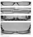
FIG. 3 shows a top down view of an embodiment of the eyeglass frame system;
FIG. 4 shows a rear perspective view an embodiment of the eyeglass frame system;
FIG. 5 shows a perspective view of an alternative embodiment of the eyeglass frame system;
FIG. 6 shows a rear perspective view of the horizontal bar separated of the front section of the eyeglass frame system;
FIG. 7 shows a perspective view of a lens partially disposed in an eye rim of the front section of the eyeglass frame system;
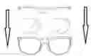
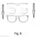
FIG. 8—This illustration shows a front view of the components of the invention; and
FIG. 9—This illustration shows a perspective view of the components of the invention.
IDENTIFICATION OF PARTS/COMPONENTS OF INVENTION
Please note that not all EYEGLASS Frames will utilize all parts listed.
- 10—Frame Front—Front part of the eyeglass frame that holds the lenses in place and bridges the top of the nose.
- 11—Frame Front Backside—This is the Frame Front backside where the magnets will be placed and serve self guidance for the Removable Horizontal Bar.
- 12—Bridge—The area between the lenses that go over the nose and supports 90 percent of the weight of the eyeglasses.
- 14—Eye Wire/Rims—Part of the frame front into which the lenses are inserted.
- 15—Lens—the lens of the eyeglasses.
- 16—End Pieces—Extensions of the frame front to which the temples are attached.
- 18—Hinges—Part of the frame that connects the frame front to the temples and allows the temples to swing.
- 20—Temples—Parts of the frame that extend over and/or behind the ears to help hold the frame in place.
- 24—Nose Pads—Plastic pieces that may be attached directly to the frame or to pad arms. They help keep the frame in its proper position (Our design does not use Pad Arms).
- 26—Keyhole Bridge—Refers to the specific shape of bridge sits across the nose and connects the two lenses.
- 28—Horizontal Top Bar (Rear Only)—Removable back piece of frame that connects to rear of the Front Eye Wire/Rim and allows lens to be removed or added.
- 30—Magnet—Neodymium magnet providing Horizontal Bar self guidance.
- 32—Frame Click (Release Mechanism)—Slightly rounded and recessed to keep horizontal bar against frame front rear and serve as a way to keep horizontal bar in place (stability).
- 34—Frame Rear—Rear part of the eyeglass frame that holds the lenses in place and bridges the frame click.
- Removable Horizontal Top Bar back frame—This is a part of the horizontal bar that is removable allowing lenses to be removed from the frame cradle holding the lenses in place.
- Release Mechanism—a small plastic impression assisting with the release of the removable horizontal bar back frame.
- Modified Frame with “solid horizontal bar”—Allows a pair of glasses frame to look like standard frames, however it provides the home position for the removable horizontal bar back frame and is the primary support frame for the lenses and other glasses components (temple, bridge, ear pieces, etc).
DETAILED DESCRIPTION OF THE PREFERRED EMBODIMENT
There are a number of significant design features and improvements incorporated within the invention.
The intention of this invention is to allow consumers of eye wear to purchase one set of prescription or non-prescription lenses and utilize them into a multitude of similar frames. It also allows some consumers to interchange designer lenses into the same frame.
A standard frame normally consist of a frame front 10, frame front backside 12, eye wire/rims 14 and end piece 16. This invention focuses on specific components of the frame previously considered to be one solid piece. The major change is in the horizontal bar area (frame front 10 and removable horizontal bar 28) of a frame. Specifically there is no other invention that utilizes a two piece horizontal bar with a removable back bar 28 while maintain the frame strength of a solid front 10 horizontal bar attached to the remainder of the frame portions (bridge 12, keyhole bridge 26, eye wire/rim 14, end pieces 16, hinges 18 and temple 20). The “horizontal bar” has a front 10 and a back 28 as shown in FIG. 3. The back portion of the horizontal bar is removable 28 allowing the lens 15 to slide in its standard frame channels 14. This back removable portion of the horizontal bar 28 is locked into place by utilizing magnets 30 as shown in FIG. 2 and FIG. 6.
The “horizontal bar” front is a continuous portion of the frame 10 providing structure and durability to the frame.
The removable back of the “horizontal bar” 28 rides above the bridge section 12 of the glasses. This is important for comfort of the bridge 12/nose pieces 24 and interaction with the actual nose resting spots.
With minimal pressure the removable portion of the “horizontal bar” 28 can be removed. This allows for the lens 15 to be simply pulled up from the lens cradle 14 as shown in FIG. 7. The removable portion is replaced by positioning the “back horizontal bar” 28 in its guiding position and the magnets 30 pull the bar into place.
At this time the lenses 15 are available to put the current lenses 15 into another pair of frames with the same lens 15 shape, but different frame color, style, design etc.
Lens 15 to the Modified Frame with “solid front horizontal bar” 10. This frame is built like most frames with a grooved cradle that the lens 15 slides into allowing for the lens 15 to be secured into the frame. The lens 15 is a standard shape, size as specified by designer or brand. The Modified Frame with “solid front horizontal bar” 10 is a unique relationship because it gives the appearance of a solid frame; however it allows the lens 15 to be slid into the frame. This allows the lenses 15 to be removed and slid into another frame with the same lens 15 shape.
The modified Frame with “solid front horizontal bar” 10 relationship to “Removable Horizontal Bar Back Frame 28 does not exist today in marketed glasses. All marketable glasses today that are not frameless or partial frames use a solid frame that entraps the lens. The proprietary nature of the eyeglass frame identifies the horizontal bar 10 as a piece of the glasses frame. The relationship between the frame and the removable horizontal bar back 28 is critical because this is the mechanism that locks the lenses 15 into place. The removable horizontal back bar 28 is held into place using Neodymium Magnets 30 in the preferred embodiment. The two pieces horizontal bar 10 and horizontal back bar 28 are manufactured with matching step surfaces and the magnets 30 hold the removable horizontal back bar 28 in place.
The relationship of the Bridge 12 to the modified frame with solid front horizontal bar 10 is important in that the bridge 12 is always continuous with no splits/break or obstructions that develops an edge point on the bridge of the nose.
The relationship of the release mechanism 32 to the removable horizontal back bar 28 and the modified frame with solid front horizontal bar 10 is to allow for a wedge release mechanism 32 to help assist with separating the horizontal back bar 28 from the modified frame with solid front horizontal bar 10 from the Neodymium Magnetic forces of the Neodymium Magnets 30.
FIG. 1 shows a front view of eyeglasses with Frame Front 10 having multiple parts including Bridge 12 which is between the lenses 15 and goes over the nose, Eye Wire/Rims 14 which is part of the Frame Front 10 and where lenses 15 are inserted, End Pieces 16 which are extensions of the Frame Front 10 and where the Temples 20, as shown in FIG. 3 are attached, and showing Keyhole Bridge 26 underneath the Bridge 12.
FIG. 2 shows a back view of eyeglasses with Frame Click 32 serves as fastening mechanism for Removable Horizontal Bar 28, Neodymium Magnets 30 are used to fasten the Removable Horizontal Bar 28 against Frame Front Backside 11 and provide it self guidance. Where FIG. 3 shows both the Frame Front 10 and the Removable Horizontal Bar 10 securely against each other, the Frame Click 32 along with the Magnets 30 hold the Removable Horizontal Bar 28 in place securing the lenses.
This invention focuses on a major change in the “horizontal bar” 10 of the frame. The “horizontal bar” has a front 10 and a back 28. The back portion of the horizontal bar is removable allowing the lens 15 to slide in its standard frame channels 14. This back removable portion of the horizontal bar 28 is locked into place by utilizing magnets 30. The adjoining sides of the removable horizontal back bar 28 and the horizontal bar front 10 are matched surfaces allowing self-guidance which enhances the strength of the bond between the horizontal bar front 10 and the removable horizontal back bar 28 as it is adhered by the magnetic forces 30.
The “horizontal bar” front 10 is a continuous portion of the frame providing structure and durability to the frame. The removable back of the “horizontal bar”28 rides above the bridge section 12 of the glasses. This is important for comfort of the bridge/nose pieces 12 which may include the nose pads 24 and interaction with the actual nose resting spots.
With minimal pressure the removable portion of the “horizontal bar” 28 can be removed. This allows for the lens 15 to be simply pulled up from the lens cradle. (see FIG. 7) The removable portion is replaced by positioning the “back horizontal bar” 28 to the matched step finish guiding it into position allowing magnets 32 to pull the bar into place.
The components of the current invention are shown in FIGS. 8 and 9 showing the lens, horizontal bar 10 and the removable horizontal back bar 28.
The eyeglasses frames of the current invention will function in an ordinary fashion with the following parts of the eyeglass Frames model. The ‘Frame Front 10 is the front part of the eyeglass frame that holds the lenses 15 in place and bridges the top of the nose.
The ‘Bridge’ 12 is the area between the lenses 15 that go over the nose and supports 90 percent of the weight of the eyeglasses. The ‘Eye Wire/Rims 14 are where the lenses 15 are inserted. The ‘End Pieces’ 16 are extensions of the frame front to which the temples 20 are attached. The ‘Hinges’ 18 connect the frame front 10 to the temples 18 and allows the temples 20 to swing. The ‘Temples’ 20 extend over and/or behind the ears to help hold the frame in place. The ‘Spring-Hinged Temples’ 18 include hidden springs in the hinges that help keep the frame from slipping. The ‘Nose Pads’ 24 may be attached directly to the frame or to pad arms as shown in FIG. 4. They help keep the frame in its proper position. Note that not all models use Nose Pads 24. The ‘Keyhole Bridge’ 26 sits across the nose and connects the two lenses. The ‘Horizontal Top Bar’ (Rear Only) 28 is the removable back piece of frame that connects to rear of the Front Eye Wire/Rim 10 and allows lens 15 to be removed or added. The ‘Magnets’ or ‘Neodymium Magnets’ 30 provides Horizontal Bar 28 self guidance. The ‘Frame Click’ or ‘Release Mechanism’ 32 is slightly rounded and recessed to keep horizontal bar against frame front rear and serve as a way to keep horizontal bar in place (stability).
Eyeglasses frames are typically made of either metal or a type of plastic called cellulose-acetate. Cellulose acetate is derived from cotton and is flexible and strong.
Alternative Embodiments
Alternative embodiments consist of two main items. The attachment of the removable horizontal bar back frame 28 to the solid front horizontal bar 10 is reference utilizing magnets 30. Alternative to this is built in spring clips, locking pins, or any other functional way to securing a removable frame piece to allow lens 15 replacement or exchange as shown in FIG. 5.
The release mechanism 32 may consist of any shape, size or apparatus utilized to separate frames that consist of more than one part with the intention of replacing or exchanging the lenses.
CONCLUSION
Having the flexibility to change frames of different color, style, pattern while allowing easy transition of lenses 15 from one frame to another frame using a single pair of prescribed lenses. eyeglass Frames should also provide consumer an efficient shopping experience.
As to a further discussion of the manner of usage and operation of the present invention, the same should be apparent from the above description. Accordingly, no further discussion relating to the manner of usage and operation will be provided.
With respect to the above description, it is to be realized that the optimum dimensional relationships for the parts of the invention, to include variations in size, materials, shape, form, function and manner of operation, assembly and use, are deemed readily apparent and obvious to one skilled in the art, and all equivalent relationships to those illustrated in the drawings and described in the specification are intended to be encompassed by the present invention.
Therefore, the foregoing is considered as illustrative only of the principles of the invention. Further, since numerous modifications and changes will readily occur by those skilled in the art, it is not desired to limit the invention to the exact construction and operation shown and described, and accordingly, all suitable modifications and equivalents may be resorted to, falling within the scope of the invention.
Claims
I claim:1. A device comprising; an eyeglass frame with a removable back bar that attaches to the frame and can be removed to place or remove lens from the frame.
2. A device according to claim 1 further comprising having said back bar being secured to the frame by an attachment means.
3. A device according to claim 2 further comprising having said attachment means being a plurality of magnets.
4. A device according to claim 1 further comprising having said frame having a solid front horizontal bar.
5. A device according to claim 1 further comprising the front horizontal bar having a front and a back where the back of the bar is the removable back bar.
6. A device according to claim 1 further comprising the frame has frame channels to hold the lens.
7. A device according to claim 1 further comprising the frame having a bridge.
8. A device according to claim 7 further comprising having the removable back positioned above the bridge.
9. A device according to claim 7 further comprising having the bridge have nose pieces positioned where a wearer nose would be positioned at.
10. A device according to claim 3 further comprising having the magnets being neodymium magnets.
11. A process to change lens in glass frames comprising;
having an eyeglass frame with a removable back bar that attaches to the frame;
removing the back;
placing lens into the frame; and
replacing the back.
12. A process to change lens in glass frames according to claim 11 further comprising having said back bar being secured to the frame by an attachment means.
13. A process to change lens in glass frames according to claim 12 further comprising having said attachment means being a plurality of magnets.
14. A process to change lens in glass frames according to claim 11 further comprising having said frame having a solid front horizontal bar.
15. A process to change lens in glass frames according to claim 11 further comprising the front horizontal bar having a front and a back where the back of the bar is the removable back bar.
16. A process to change lens in glass frames according to claim 11 further comprising the frame has frame channels to hold the lens.
17. A process to change lens in glass frames according to claim 11 further comprising the frame has a bridge.
18. A process to change lens in glass frames according to claim 17 further comprising having the removable back positioned above the bridge.
19. A process to change lens in glass frames according to claim 17 further comprising; having a step of removing a set of lens from the frame prior to placing a set of lens into the frames.
20. A process to change lens in glass frames according to claim 13 further comprising having the magnets being neodymium magnets.
Images & Drawings included:


Sources:
- United States Patent and Trademark Office - verify current appl. status at the USPTO↗
Recent applications in this class:
- » 20250277989 2025-09-04
EYEWEAR HAVING A PIVOTABLE LENS RETAINER - » 20250067996 2025-02-27
Self-Locking Eyeglass System - » 20250013072 2025-01-09
EYEWEAR SYSTEM WITH REPLACEABLE LENSES - » 20240427170 2024-12-26
EYEWEAR LENS COUPLING MECHANISM AND RELATED METHODS - » 20240329427 2024-10-03
FRAME - » 20220334406 2022-10-20
Eyewear having a pivotable lens retainer - » 20220317474 2022-10-06
Method for covering a primary element for optical spectacles with primary members moulded from cork particles - » 20220179234 2022-06-09
ADAPTER DEVICE FOR A LENS PANEL FOR OPTICALLY GLAZING WITH SPECTACLE LENSES - » 20220137429 2022-05-05
MULTI-LAYERED ELEMENT FOR MANUFACTURING SPECTACLE FRAMES, METHOD FOR MANUFACTURING SUCH MULTI-LAYERED ELEMENT AND SPECTACLE FRAME COMPRISING ONE OR MORE MULTI-LAYERED ELEMENTS - » 20210364819 2021-11-25
Self-locking eyeglass system
Recent applications for this Assignee:
- » 20180231796 2018-08-16
Modular eyeglass frame systems and methods for their use and manufacture