Cable
US20170243676A1
2017-08-24
15/436,847
2017-02-19
✅ Patent granted
US 10,176,907 B2
2019-01-08
-
-
Timothy Thompson | Guillermo Egoavil
Wei Te Chung | Ming Chieh Chang
2037-02-19
Abstract:
A cable (100) includes a power wire (1), a ground wire (3), data transmission wires (2) between the power wire and the ground wire, and an insulating outer layer (4) enclosing the outer side of the power wire, the ground wire, and the data transmission wires. The power wire includes a conductor (11), an insulating layer (12) outside the conductor, and a metal shielding layer (13) outside the insulating layer. The power wire and the data transmission wires are spaced from each other by plastic materials.
Inventors:
- LU-YU CHANG 31 🇹🇼 New Taipei, Taiwan
- HONG-PING WANG 4 🇨🇳 Kunshan, China
- A-NAN YANG 1 🇨🇳 Kunshan, China
Assignee:
- FOXCONN INTERCONNECT TECHNOLOGY LIMITED 922 Grand Cayman, Cayman Islands
Applicant:
Interested in similar patents?
Get notified when new applications in this technology area are published.
Classification:
H01B9/006 » CPC further
Power cables Constructional features relating to the conductors
H01B9/003 » CPC main
Power cables including electrical control or communication wires
H01B9/024 » CPC further
Power cables with screens or conductive layers, e.g. for avoiding large potential gradients composed of braided metal wire
H01B9/028 » CPC further
Power cables with screens or conductive layers, e.g. for avoiding large potential gradients with screen grounding means, e.g. drain wires
H01B9/00 IPC
Power cables
H01B9/02 IPC
Power cables with screens or conductive layers, e.g. for avoiding large potential gradients
H01B7/0823 » CPC further
Insulated conductors or cables characterised by their form; Flat or ribbon cables Parallel wires, incorporated in a flat insulating profile
H01B7/0861 » CPC further
Insulated conductors or cables characterised by their form; Flat or ribbon cables comprising one or more screens
H01B7/08 IPC
Insulated conductors or cables characterised by their form Flat or ribbon cables
Description
BACKGROUND OF THE INVENTION
1. Field of the Invention
The present disclosure relates to wire arrangement of a flat cable.
2. Description of Related Arts
Taiwan Patent No. 389916, issued on Oct. 1, 2010, discloses a cable of a flat type structure. The cable includes an outside layer enclosing data transmission wires and power transmission wires. The data transmission wires and the power transmission wires are arranged intimately close to each other.
China Patent No. 204303404, issued on Apr. 29, 2015, discloses a flat wire cable. The flat wire cable includes multiple conductive core wires conforming to Universal Serial Bus (USB) 2.0 specification. Insulation dielectric layers enclose corresponding core wires and wrapping layers enclose corresponding insulation dielectric layers. The flat wire cable further comprises an inner jacket and an outer jacket which sequentially wrap all the core wires.
An improved cable is desired.
SUMMARY OF THE INVENTION
Accordingly, an object of the present invention is to provide a flat cable with stable structure and good bending capability.
To achieve the above object, a cable includes a power wire, a ground wire, data transmission wires between the power wire and the ground wire, and an insulating outer layer enclosing the power wire, the ground wire, and the data transmission wires. The power wire includes a conductor, an insulating layer outside conductor, and a metal shielding layer outside the insulating layer. The power wire and the data transmission wire are spaced from each other by plastic materials.
Other objects, advantages and novel features of the invention will become more apparent from the following detailed description when taken in conjunction with the accompanying drawings.
BRIEF DESCRIPTION OF THE DRAWINGS
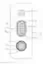
FIG. 1 is a cross-sectional view of a cable according to a first embodiment of the present invention;
FIG. 2 is an enlarged view of a power wire of the cable in FIG. 1; and
FIG. 3 is an enlarged view of a power wire according to a second embodiment.
DETAILED DESCRIPTION OF THE PREFERRED EMBODIMENT
Reference will now be made in detail to the preferred embodiment of the present invention.
Referring to FIGS. 1 and 2, a cable 100 according to a first embodiment of the present invention is shown. The cable 100 includes a power wire 1, a ground wire 3, data transmission wires 2 between the power wire 1 and the ground wire 3, and an insulating outer layer 4 enclosing the power wire 1, the ground wire 3, and the data transmission wires 2.
The cable 100 is flat and complies with USB 2.0 cable specification.
The power wire 1 includes a conductor 11, an insulating layer 12 coated outside conductor 11, and a metal shielding layer 13 coated outside the insulating layer 12. The power wire 1 and the data transmission wires 2 are filled with plastic materials to improve the bending performance of the cable 100. The metal shield layer 13 of the power wire 1 is a wound metal shield layer 131. The metal shielding layer 13 is used as a ground return with the ground wire 3 and the metal braid layer 23 of the data transmission wires 2, which is beneficial for reducing ground resistance, reducing voltage drop, and realizing fast charging.
The data transmission wires 2 include a pair of differential signal wires 21, an inner shield layer 22 coated on the outer side of the pair of differential signal wires 21, and a metal braid layer 23 coated on the outer side of the inner shield 22. The inner shield layer 22 is an aluminum foil layer. The inner shield 22 is made of aluminum foil or PET (Polyethylene terephthalate) material. Each of the differential signal wires 21 includes a signal conductor 211 and an insulating layer 212 covered on the outside of the signal conductor 211.
The ground wire 3 is a bare conductor. The power wire 3 and the data transmission wires 2 are filled with plastic materials.
Referring to FIG. 3, a power wire 1 of the cable 100 according to a second embodiment is shown. The metal shield layer 13 of the power wire 1 is a woven metal shield layer 132.
While a preferred embodiment in accordance with the present invention has been shown and described, equivalent modifications and changes known to persons skilled in the art according to the spirit of the present invention are considered within the scope of the present invention as described in the appended claims.
Claims
What is claimed is:1. A cable comprising:
a power wire;
a ground wire;
data transmission wires located between the power wire and the ground wire; and
an insulating outer layer enclosing the power wire, the ground wire, and the data transmission wires; wherein
the power wire includes a conductor, an insulating layer outside the conductor, and a metal shielding layer enclosing the insulating layer; and
the power wire and the data transmission wire are spaced from each other.
2. The cable as claimed in claim 1, wherein the cable is flat.
3. The cable as claimed in claim 1, wherein the ground wire is bare conductor.
4. The cable as claimed in claim 1, wherein the data transmission wires include a pair of differential signal wires, an inner shield layer enclosing the pair of differential signal wires, and a metal braid layer enclosing the inner shield layer.
5. The cable as claimed in claim 4, wherein the inner shield layer is an aluminum foil layer.
6. The cable as claimed in claim 1, wherein the metal shield layer of the power wire has a wound structure.
7. The cable as claimed in claim 1, wherein the metal shield layer of the power wire has a woven structure.
8. A cable comprising:
a power wire used for transmitting power;
a ground wire;
data transmission wires located between the power wire and the ground wire in a transverse direction; and
an insulating outer layer enclosing the power wire, the ground wire, and the data transmission wires; wherein
the power wire includes a conductor, a metal shielding layer surrounding the power wire, and an insulating layer intimately coated therebetween radially; and
the data transmission wires, the power wire and the ground wire are essentially aligned with each other along said transverse direction, and are spaced from one another with corresponding gaps therebetween in said transverse direction.
9. The cable as claimed in claim 8, wherein the ground wire and the data transmission wires are filled with plastic.
10. The cable as claimed in claim 8, wherein the cable is flat.
11. The cable as claimed in claim 8, wherein the ground wire is bare conductor.
12. The cable as claimed in claim 8, wherein the data transmission wires include a pair of differential signal wires, an inner shield layer coated on the outer side of the pair of differential signal wires and a metal braid layer coated on the outer side of the inner shield layer
13. The cable as claimed in claim 8, wherein the inner shield is an aluminum foil layer.
14. The cable as claimed in claim 8, wherein the differential signal wires include signal conductor and an insulating layer covered on the outside of the signal conductor.
15. The cable as claimed in claim 8, wherein the differential signal wires are parallel and close together.
16. The cable as claimed in claim 8, wherein the metal shield layer of the power wire has a wound structure or a woven structure.
17. The cable as claimed in claim 8, wherein the cable is USB 2.0 cable.
Images & Drawings included:


Sources:
- United States Patent and Trademark Office - verify current appl. status at the USPTO↗
Similar patent applications:
- » 20190334306
Cable end holding device for holding a cable end of a cable, method for positioning a cable end of a cable, and cable assembly machine for assembling a cable - » 20190131780
Method of connecting a first cable to a second cable, cable arrangement, and cable connection device for connecting a first cable to a second cable - » 20230230728
CABLE ALIGNMENT APPARATUS AND METHOD FOR ALIGNING ASSEMBLED CABLE ENDS OF TWO CABLES OF A CABLE HARNESS IN THE CORRECT ROTATIONAL POSITION AS WELL AS ARRANGEMENT FOR ASSEMBLING PLUG HOUSINGS WITH CABLE ENDS WITH THE CABLE ALIGNMENT APPARATUS - » 20180215593
Cable-cutting unit for a cable winch, cable-cutting system for a cable winch and method for operating a cable-cutting unit for a cable winch - » 20190007094
Cable modem transceiver, cable modem, cable modem communication system, processor for a cable modem transceiver, method for calibrating a cable modem transceiver, and computer program - » 20160372232
CABLE CORE FOR A CABLE, IN PARTICULAR AN INDUCTION CABLE, CABLE, AND METHOD FOR PRODUCING A CABLE CORE - » 20060053944
Cable release system, an assembly for securing a cable sheath of a cable release system to a product, and a product having an assembly for securing a cable sheath of a cable release system - » 20060294560
Cable broadcasting system, cable broadcasting transmitting apparatus, cable broadcasting receiver, open cable broadcasting receiver and cable card - » 20070251714
Cable outlet element, cable outlet device, cable outlet arrangement, method for producing a cable element and the use of a cable outlet element in an aircraft - » 20140263289
Method for producing a cable core, having a conductor surrounded by an insulation, for a cable, in particular for an induction cable, and cable core and cable
Recent applications in this class:
- » 20250182931 2025-06-05
ELECTRICAL MAINS CABLE - » 20250104886 2025-03-27
COMPOSITE CABLE AND COMPOSITE HARNESS - » 20240170183 2024-05-23
COMPOSITE CABLE - » 20240145128 2024-05-02
Multi-core cable - » 20230162888 2023-05-25
Cable for distributing network power and data - » 20230059240 2023-02-23
Charging Cable for an Electric Vehicle with Communication Capability - » 20220415539 2022-12-29
Multicore cable - » 20220270785 2022-08-25
Portable charging light-emitting cable for new energy vehicles - » 20220215985 2022-07-07
COMBINATION CABLE FOR ELECTRICAL ENERGY AND DATA TRANSMISSION - » 20220208417 2022-06-30
Power unit and power cable for mobile communication base station
Recent applications for this Assignee:
- » 20240199157 2024-06-20
METHOD OF CONTROLLING STATE OF ELECTRIC ASSIST BICYCLE, CONTROL SYSTEM, AND ELECTRONIC DEVICE - » 20240177887 2024-05-30
CORE WIRE AND METHOD OF MAKING SAME AND CABLE INCLUDING THE CORE WIRE - » 20240072477 2024-02-29
ELECTRICAL CONNECTOR WITH IMPROVED CONTACTS - » 20240055792 2024-02-15
Electrical connector having an angled part and a U-shaped plate together defining a tubular structure - » 20230352880 2023-11-02
ELECTRICAL CONNECTOR WITH IMPROVED INSERTING MEMBER - » 20230335934 2023-10-19
ELECTRICAL CONNECTOR - » 20230307870 2023-09-28
Electrical connector assembly having improved locking elements - » 20230283018 2023-09-07
ELECTRICAL CONNECTOR ASSEMBLY WITH IMPROVED TERMINALS - » 20230268679 2023-08-24
Electrical connector assembly - » 20230238732 2023-07-27
ELECTRICAL CONNECTOR ASSEMBLY HAVING A METAL PLATE FOR MOUNTING A CONNECTOR TO A HOUSING