Forming a Box Using a C-Case
US20170259947A1
2017-09-14
15/064,346
2016-03-08
Abstract:
This invention is directed to designing a machine and a box so that one apparatus can be used for inserting the bundle from the top and the side by using two pieces of cardboard. One piece of the Cardboard is formed into U Channel for loading a bundle into the U Channel from the side or top.
Interested in similar patents?
Get notified when new applications in this technology area are published.
Classification:
B65B5/028 » CPC further
Packaging individual articles in containers or receptacles, e.g. bags, sacks, boxes, cartons, cans, jars; Machines characterised by incorporation of means for making the containers or receptacles for making containers from preformed blanks for making containers from two or more blanks
B65B5/06 » CPC main
Packaging individual articles in containers or receptacles, e.g. bags, sacks, boxes, cartons, cans, jars Packaging groups of articles, the groups being treated as single articles
B65B43/08 » CPC further
Forming, feeding, opening or setting-up containers or receptacles in association with packaging Forming three-dimensional containers from sheet material
B65B43/42 » CPC further
Forming, feeding, opening or setting-up containers or receptacles in association with packaging Feeding or positioning bags, boxes, or cartons in the distended, opened, or set-up state; Feeding preformed rigid containers, e.g. tins, capsules, glass tubes, glasses, to the packaging position; Locating containers or receptacles at the filling position ; Supporting containers or receptacles during the filling operation
B65B5/02 IPC
Packaging individual articles in containers or receptacles, e.g. bags, sacks, boxes, cartons, cans, jars Machines characterised by incorporation of means for making the containers or receptacles
B65B7/16 » CPC further
Closing containers or receptacles after filling Closing semi-rigid or rigid containers or receptacles not deformed by, or not taking-up shape of, contents, e.g. boxes or cartons
Description
FIELD OF THE INVENTION
This invention relates to packing a box with a bundle of articles or an article by inserting the bundle into the box while the box is on a conveyor. The bundle can be inserted into the box from the top of the box or pushed into the box from the side of the box. The bundle can contain a number of articles such as bottles or containers.
BACKGROUND OF THE INVENTION
In the prior art bundles of articles are usually placed inside a cardboard box. The two common types of boxes are RSC boxes or wrap around boxes The RSC is a box made from a single piece of card board with flaps. The flaps are usually bent to form the top and bottom of the box. The bottom of the box can be glued or taped to form the box. A bundle of articles is inserted in the open box from the top of the box. The flaps are bent to form the top of the box. The flaps are taped or glued to hold the flaps in position. The wrap around box uses a single piece of cardboard having flaps. When the box is wrapped the flaps are on the sides of the box. A leaver on the wrap around machine allows the bundle to be inserted from the top or from the side of the box. A pick and place machine is conventionally used to place a bundle in the box from the top. Likewise a pusher can slide the bundle into the side opening of the box.
SUMMARY OF THE INVENTION
An objective of the invention is to use less cardboard. Another objective of the invention is to produce an apparatus designed to either allow the bundle to be inserted from the top by a pick and place machine or allow the bundle to be pushed into the box from the side. This invention is directed to designing a machine and a box so that one apparatus can be used for inserting the bundle from the top and the side by using two pieces of cardboard.
BRIEF DESCRIPTION OF THE DRAWING
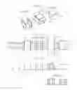
FIG. 1 shows a C case in the shape as a U channel.
FIG. 2 shows a top sheet placed on top of the U Channel.
FIG. 3 shows a box formed by folding the top sheet to form a box.
FIGS. 4, 5 and 6 shows a U Channel place on a bucket conveyor.
DESCRIPTION OF THE INVENTION
FIG. 1 shows a first piece of cardboard 1 bend at score lines 2 to form a C Case 5 shaped as a U-Channel. The U-Channel has vertical sides 15 and 16 connected to bottom 17, The perimeter of the C Case 5 has extensions such as flaps 3 to be used for gluing to another piece of cardboard 4. FIG. 2 shows a cardboard 4 placed on the top of the C Case 5. Cardboard 4 has three sections 6, 7 and 8. FIG. 3 shows section 6 covering the top opening of the C Case and sections 7 and 8 cover the side opening of the C Case to form a box 9. The flaps 3 bond the C case to the second piece of cardboard. FIG. 4 and side view FIG. 5 show a moving bucket conveyor 10 having a C case 5 placed in a bucket 11. The sides of the C Case are held in place by the bucket conveyor. Having the top and sides open, a bundle 12 can be placed on the bottom 17 of the C Case by using a pick and place machine to insert the bundle from the top. In the alternative the bundle can be pushed through the side opening of the C case 5 onto bottom 17. After the bundle or bundles are placed in the C case, the cardboard 4 is placed on top of the C case. Optionally fingers 13 keep section 7 and 8 in a temporary vertical position before folding of the (tabs) flaps. Sections 7 and 8 are bend along their score lines 2 to form a C shape (u-Channel). At substantially the same time, the flaps 3 of the first piece are bent into position to be glued on the sides of cardboard 4 to form box 14. The movement of the conveyor can be continuous or intermittent depending on the desired movement of the conveyor
Claims
1. A process of forming a box with a first and second piece of cardboard comprising,
forming the first piece of cardboard into a U-channel having an open sides and open top having extensions along the perimeter for bonding to the second piece of cardboard,
placing the U-channel on a conveyor
placing a bundle into the a U channel,
placing the second piece of cardboard on top of the U channel to covers up the top opening of the U-channel,
bending the second piece of cardboard to cover up the open sides of the first piece of cardboard, and
bonding the extensions from first of cardboard to the second piece of cardboard to form a box.
2. A process according to claim 1 wherein the extension are flaps on the perimeter of the first piece of cardboard for bonding to the second piece of cardboard.
3. A process according to claim 1 including placing the bundle into the U Channel from a side of the U Channel.
4. A process according to claim 1 including placing the bundle into the U Channel from the top of the U Channel.
5. An apparatus for forming a box on a conveyor with a first and second piece of cardboard comprising,
means for forming the first piece of cardboard into a U-channel having open sides and an open top with extensions around the perimeter for bonding to the second piece of cardboard,
means for placing the U-channel on a conveyor,
means for placing a bundle into the U channel,
means for placing the second piece of cardboard on top of the U channel to covers up the top opening of the U-channel,
means for bending the second piece of cardboard to cover up the open sides of the U-channel,
means for bonding extensions along the perimeter along the first piece of cardboard to the second piece of cardboard to form a box.
6. An apparatus according to claim 5 wherein the means for placing the bundle into the U Channel includes means for placing the bundle into the U Channel from the side or top of the U Channel.
Images & Drawings included:

Sources:
- United States Patent and Trademark Office - verify current appl. status at the USPTO↗
Recent applications in this class:
- » 20240359838 2024-10-31
APPARATUSES AND METHODS FOR LOADING CONTAINERS WITH PRODUCTS - » 20240317436 2024-09-26
METHOD AND SYSTEM FOR MANUFACTURING A SHEET OF LAUNDRY DETERGENT - » 20240116660 2024-04-11
APPARATUS AND METHOD FOR TRANSPORTING PRODUCTS - » 20240101290 2024-03-28
Automated method and system for packaging flexible articles - » 20240025580 2024-01-25
METHOD AND BUNDLING UNIT FOR CARRYING OUT A MULTI-LAYERED PACKAGING SYSTEM - » 20230415933 2023-12-28
Apparatuses and methods for loading containers with products - » 20230182935 2023-06-15
Packaging process, packaging apparatus and related control system - » 20220267035 2022-08-25
Apparatuses and methods for loading containers with products - » 20210237913 2021-08-05
System and method for assisting error recovery in an automated packaging process and system and method for automatically packaging shipment sets - » 20210139173 2021-05-13
Automatic food-boxing device for cooked food of food frying machines