Acoustic sensor and home appliance system comprising the same
US20170268924A1
2017-09-21
15/458,523
2017-03-14
✅ Patent granted
US 10,371,568 B2
2019-08-06
-
-
Natalie Huls
Ked & Associates LLP
2037-07-20
Abstract:
Provided are an acoustic sensor and a home appliance system comprising the same. The acoustic sensor comprises a communication unit, a microphone to collect an acoustic signal, a memory to store a failure acoustic signal of a home appliance, and a processor, wherein in response to the acoustic signal, collected by the microphone, corresponding to the failure acoustic signal of the home appliance, the processor transmits the collected acoustic signal, or data corresponding to the collected acoustic signal, to an external server or a terminal. Accordingly, failure of the home appliance may be easily diagnosed.
Inventors:
- Lagyoung Kim 17 🇰🇷 Seoul, South Korea
- Taedong SHIN 6 🇰🇷 Seoul, South Korea
- Jihyun SONG 6 🇰🇷 Seoul, South Korea
Assignee:
- LG ELECTRONICS INC. 44,418 🇰🇷 Seoul, South Korea
Applicant:
Interested in similar patents?
Get notified when new applications in this technology area are published.
Classification:
A47L11/4008 » CPC further
Machines for cleaning floors, carpets, furniture, walls, or wall coverings; Parts or details of machines not groups - , , e.g. handles, arrangements of switches, skirts, buffers, levers; Installations of electric equipment Arrangements of switches, indicators or the like
A47L11/40 IPC
Machines for cleaning floors, carpets, furniture, walls, or wall coverings Parts or details of machines not groups - , , e.g. handles, arrangements of switches, skirts, buffers, levers
F24F11/00 IPC
Control or safety arrangements
G01V8/10 » CPC further
Prospecting or detecting by optical means Detecting, e.g. by using light barriers
G08B21/18 IPC
Alarms responsive to a single specified undesired or abnormal condition and not otherwise provided for Status alarms
G08B21/187 » CPC further
Alarms responsive to a single specified undesired or abnormal condition and not otherwise provided for; Status alarms Machine fault alarms
G01H11/00 » CPC main
Measuring mechanical vibrations or ultrasonic, sonic or infrasonic waves by detecting changes in electric or magnetic properties
F25D29/00 » CPC further
Arrangement or mounting of control or safety devices
D06F39/00 IPC
Details of washing machines not specific to a single type of machines covered by groups -
G10L25/51 » CPC further
Speech or voice analysis techniques not restricted to a single one of groups - specially adapted for particular use for comparison or discrimination
F25D29/008 » CPC further
Arrangement or mounting of control or safety devices Alarm devices
G08B21/04 IPC
Alarms responsive to a single specified undesired or abnormal condition and not otherwise provided for; Alarms for ensuring the safety of persons responsive to non-activity, e.g. of elderly persons
G08B13/16 IPC
Burglar, theft or intruder alarms Actuation by interference with mechanical vibrations in air or other fluid
G01V8/12 » CPC further
Prospecting or detecting by optical means; Detecting, e.g. by using light barriers using one transmitter and one receiver
A47L2201/00 » CPC further
Robotic cleaning machines, i.e. with automatic control of the travelling movement or the cleaning operation
G08B13/1672 » CPC further
Burglar, theft or intruder alarms; Actuation by interference with mechanical vibrations in air or other fluid using passive vibration detection systems using sonic detecting means, e.g. a microphone operating in the audio frequency range
G08B21/0208 » CPC further
Alarms responsive to a single specified undesired or abnormal condition and not otherwise provided for; Alarms for ensuring the safety of persons; Child monitoring systems using a transmitter-receiver system carried by the parent and the child; Specific application combined with child monitoring using a transmitter-receiver system Combination with audio or video communication, e.g. combination with "baby phone" function
A47L9/2894 » CPC further
Details or accessories of suction cleaners, e.g. mechanical means for controlling the suction or for effecting pulsating action; Storing devices specially adapted to suction cleaners or parts thereof; Carrying-vehicles specially adapted for suction cleaners; Installation of the electric equipment, e.g. adaptation or attachment to the suction cleaner; Controlling suction cleaners by electric means Details related to signal transmission in suction cleaners
A47L9/28 IPC
Details or accessories of suction cleaners, e.g. mechanical means for controlling the suction or for effecting pulsating action; Storing devices specially adapted to suction cleaners or parts thereof; Carrying-vehicles specially adapted for suction cleaners Installation of the electric equipment, e.g. adaptation or attachment to the suction cleaner; Controlling suction cleaners by electric means
G08B1/08 » CPC further
Systems for signalling characterised solely by the form of transmission of the signal using electric transmission ; transformation of alarm signals to electrical signals from a different medium, e.g. transmission of an electric alarm signal upon detection of an audible alarm signal
F24F2110/00 » CPC further
Indexing scheme associated with group , relating to control inputs, e.g. measured or estimated values or parameters
F24F2110/00 » CPC further
Control inputs relating to air properties
F24F2130/40 » CPC further
Control inputs relating to environmental factors not covered by group Noise
F25D2700/02 » CPC further
Means for sensing or measuring; Sensors therefor Sensors detecting door opening
G08B13/187 » CPC further
Burglar, theft or intruder alarms; Actuation by interference with heat, light, or radiation of shorter wavelength; Actuation by intruding sources of heat, light, or radiation of shorter wavelength using active radiation detection systems by interference of a radiation field
G08B21/02 » CPC further
Alarms responsive to a single specified undesired or abnormal condition and not otherwise provided for Alarms for ensuring the safety of persons
G08B21/043 » CPC further
Alarms responsive to a single specified undesired or abnormal condition and not otherwise provided for; Alarms for ensuring the safety of persons responsive to non-activity, e.g. of elderly persons based on behaviour analysis detecting an emergency event, e.g. a fall
G08B29/183 » CPC further
Checking or monitoring of signalling or alarm systems; Prevention or correction of operating errors, e.g. preventing unauthorised operation; Prevention or correction of operating errors Single detectors using dual technologies
F24F11/30 » CPC further
Control or safety arrangements for purposes related to the operation of the system, e.g. for safety or monitoring
G08B17/00 » CPC further
Fire alarms; Alarms responsive to explosion
G01H3/10 » CPC further
Measuring characteristics of vibrations by using a detector in a fluid Amplitude; Power
G08B29/18 IPC
Checking or monitoring of signalling or alarm systems; Prevention or correction of operating errors, e.g. preventing unauthorised operation Prevention or correction of operating errors
D06F39/14 » CPC further
Details of washing machines not specific to a single type of machines covered by groups - ; Casings; Tubs Doors or covers; Securing means therefor
G08B21/0469 » CPC further
Alarms responsive to a single specified undesired or abnormal condition and not otherwise provided for; Alarms for ensuring the safety of persons responsive to non-activity, e.g. of elderly persons; Sensor means for detecting Presence detectors to detect unsafe condition, e.g. infrared sensor, microphone
Description
CROSS-REFERENCE TO RELATED APPLICATION
This application claims the priority benefit of Korean Patent Application No. 10-2016-0031045, filed on 15 Mar. 2016 in the Korean Intellectual Property Office, the disclosure of which is incorporated herein by reference.
BACKGROUND OF THE INVENTION
1. Field of the invention
The present invention relates to an acoustic sensor and a home appliance system comprising the same, and more particularly, to an acoustic sensor and a home appliance system comprising the same, in which the acoustic sensor may enable easy diagnosis of failure of a home appliance.
2. Description of the Related Art
Among home appliances installed in a building for users, a refrigerator stores food, a washing machine washes laundry, an air conditioner controls indoor temperature, and a cooking device cooks food, and the like.
With the development of various communication schemes, research has been conducted on many methods to improve user convenience in using these home appliances.
SUMMARY OF THE INVENTION
The present invention provides an acoustic sensor and a home appliance system comprising the same, in which the acoustic sensor may enable easy diagnosis of failure of a home appliance.
In accordance with an aspect of the present invention, the above and other objects can be accomplished by the provision of an acoustic sensor comprising a communication unit, a microphone to collect an acoustic signal, a memory to store a failure acoustic signal of a home appliance, and a processor, wherein in response to the acoustic signal, collected by the microphone, corresponding to the failure acoustic signal of the home appliance, the processor transmits the collected acoustic signal, or data corresponding to the collected acoustic signal, to an external server or a terminal.
According to another aspect of the present invention, there is provided a home appliance system comprising a home appliance, an acoustic sensor attached to the home appliance or disposed near the home appliance, and a server, wherein in response to a failure acoustic signal of the home appliance being collected by the acoustic sensor, the server receives the failure acoustic signal of the home appliance, or data corresponding to the failure acoustic signal of the home appliance, from the acoustic sensor.
BRIEF DESCRIPTION OF THE DRAWINGS
FIG. 1 is a diagram illustrating a structure of a home appliance system according to an embodiment of the present invention.
FIGS. 2A to 2E are diagrams illustrating various examples of a home appliance.
FIG. 3 is a block diagram illustrating an internal structure of the home appliance system illustrated in FIG. 1.
FIG. 4 is a block diagram illustrating an internal structure of an acoustic sensor illustrated in FIG. 1.
FIG. 5 is a diagram illustrating an example of arrangement of home appliances and acoustic sensors installed in the home appliance system illustrated in FIG. 1.
FIGS. 6A to 15D are reference diagrams explaining the operation of the acoustic sensors and a server illustrated in FIG. 5.
DETAILED DESCRIPTION OF THE PREFERRED EMBODIMENTS
Hereinafter, embodiments of the present invention will be described in detail with reference to the accompanying drawings.
In the following description, the terms “module” and “unit”, which are used herein to signify components, are merely intended to facilitate explanation of the present invention, and the terms do not have any distinguishable difference in meaning or role. Thus, the terms “module” and “unit” can be used interchangeably.
FIG. 1 is a diagram illustrating a structure of a home appliance system according to an embodiment of the present invention.
Referring to FIG. 1, the communication system 50 according to an embodiment of the present invention comprises a home appliance 200, an Access Point (AP) device 400, a server 500, and a network 550. In addition, the communication system 50 may further comprise a terminal (not shown).
The terminal 600 may be a mobile terminal, such as a cellular phone, a smart phone, a tablet PC, a wearable device, and the like, or a fixed terminal, such as a monitor, television, and the like.
The home appliance 200 is an electric device for a user, and examples thereof comprise a refrigerator 200a (in FIG. 2), a washing machine 200b (in FIG. 2), an air conditioner 200C (in FIG. 2), a cooking device 200d (in FIG. 2), a robot cleaner 200e (in FIG. 2), and the like.
The home appliance 200 comprises a sound output unit 247 (in FIG. 3), and in the event of failure, the home appliance 200 may output an acoustic signal through the sound output unit 247 for failure diagnosis.
The Access Point (AP) device 400 may provide an internal network 10 to a nearby electric device. Particularly, the AP device 400 may provide a wireless network.
Further, the AP device 400 may exchange data with the acoustic sensor 100 in the internal network 10. That is, the AP device 400 may allocate wireless channels to a plurality of acoustic sensors 100 using a specific communication scheme, and may perform wireless communication through the wireless channels. The communication scheme may be WiFi communication, ZigBee communication, or Bluetooth communication.
The mobile terminal (not shown) installed in the internal network 10 may receive an acoustic signal or data from the acoustic sensor 100 via the AP device 40, and based on the received acoustic signal or data, the mobile terminal may monitor the home appliance 200 and the like.
Moreover, the AP device 400 may perform data communication with an external electronic device through an external network 550 in addition to the internal network 10.
For example, the AP device 400 may perform wireless data communication with the mobile terminal (not shown), which is located at an external position, through the external network 550.
In this case, the mobile terminal (not shown) located in the external network 550 may receive an acoustic signal or data from the acoustic sensor 100 through the external network 550 and the AP device 400, and based on the received acoustic signal or data, the mobile terminal may monitor the home appliance 200 and the like.
In another example, the AP device 400 may perform wireless data communication with the server 500, which is located at an external position, through the external network 550.
The server 500 may be a web server that is operated by a manufacturer of the home appliance.
The server 500 may receive an acoustic signal or data from the acoustic sensor 100, and based on the received acoustic signal or data, the server 500 may monitor the home appliance 200 and the like.
Further, the server 500 may comprise a speech recognition algorithm. Upon receiving sound data from the acoustic sensor 100, the server 500 may convert the received sound data into text-format data, and may transmit the text-format data to the acoustic sensor 100.
The home appliance system 50 according to an embodiment of the present invention comprises: the home appliance 200; the acoustic sensor 100 which is attached to the home appliance 200, or is disposed near the home appliance 200; and the server 500, in which in the case where the acoustic sensor 100 collects a failure acoustic signal of the home appliance 200, the server 500 receives the collected acoustic signal, or data corresponding to the collected acoustic signal. Accordingly, by using the acoustic sensor 100, failure of the home appliance may be easily diagnosed.
In this manner, there is no need to provide a separate communication unit for the home appliance 20, such that failure may be diagnosed easily by using the acoustic sensor 100.
In the case where the acoustic signal, collected by the acoustic sensor 100, corresponds to a failure acoustic signal of the home appliance 200, the server 500 may determine that the home appliance 20 has broken down, based on the failure acoustic signal of the home appliance 200.
Further, in the case where the acoustic signal, collected by the acoustic sensor 100, corresponds to an operation acoustic signal of the home appliance 200, the server 500 may receive the collected acoustic signal, or data corresponding to the collected acoustic signal, from the acoustic sensor 100.
In addition, in the case where the acoustic signal, collected by the acoustic sensor 100, corresponds to an operation acoustic signal of the home appliance 200, the server 500 may determine an operation state of the home appliance 200 based on the operation acoustic signal of the home appliance 200.
Moreover, in the case where the door of the home appliance 200 is opened or closed while the acoustic sensor 100 is attached to the home appliance 200, the server 500 may receive a door opening or closing acoustic signal collected by the acoustic sensor 100, or data corresponding to the door opening or closing acoustic signal, from the acoustic sensor 100.
In addition, in the case where the acoustic signal, collected by the acoustic sensor 100, corresponds to the door opening or closing acoustic signal of the home appliance 200, the server 500 determines the opening or closing of the door of the home appliance 200 based on the door opening or closing acoustic signal of the home appliance 200.
Further, in the case where a moving object is detected based on output infrared light, which is output from the sensor unit 120, and received infrared light, which is received by the sensor unit 120, the server 500 may receive a warning signal from the acoustic sensor 100. In response to the warning signal, the server 500 may transmit a predetermined sound to the acoustic sensor 100.
The acoustic sensor 100 according to an embodiment of the present invention comprises: a communication unit 135; a microphone 110 which collects an acoustic signal; a memory 140 which stores a failure acoustic signal of the home appliance 200; and a processor 170, in which in the case where an acoustic signal, collected by the microphone 110, corresponds to the failure acoustic signal of the home appliance 200, the processor 170 transmits the collected acoustic signal, or data corresponding to the collected acoustic signal, to an external server 500 or a terminal. In this manner, failure of the home appliance may be easily diagnosed, thereby improving user convenience in using the home appliance.
In the case where an acoustic signal, collected by the microphone 110, corresponds to the failure acoustic signal of the home appliance 200, the acoustic sensor 100 may determine that the home appliance 200 has broken down, based on the failure acoustic signal of the home appliance 200.
Further, in the case where an acoustic signal, collected by the microphone 110, corresponds to an operation acoustic signal of the home appliance 200, the acoustic sensor 100 may transmit the collected acoustic signal, or data corresponding to the collected acoustic signal, to the external server 500 or the terminal.
Moreover, in the case where an acoustic signal, collected by the microphone 110, corresponds to an operation acoustic signal of the home appliance 200, the acoustic sensor 100 may determine an operation state based on the operation acoustic signal of the home appliance 200.
Further, the door of the home appliance 200 is opened or closed while the acoustic sensor 100 is attached to the home appliance 200, the acoustic sensor 100 may transmit a door opening or closing acoustic signal collected by the microphone 110, or data corresponding to the door opening or closing acoustic signal, to the external server 500 or the terminal.
In addition, in the case where an acoustic signal, collected by the microphone 110, corresponds to the door opening or closing acoustic signal of the home appliance 200, the acoustic sensor 100 may determine the opening of closing of the door of the home appliance 200 based on the door opening or closing acoustic signal of the home appliance 200.
Further, in the case where an acoustic signal, indicating an operation mode input for a specific home appliance 200, is input through the microphone 110, the acoustic sensor 100 may enter an operation mode for the home appliance 200.
In the case where the acoustic signal, collected by the microphone 110, is at a reference level or higher, the acoustic sensor 100 may activate the sensor unit 120 which is in an inactive state, such that power consumption may be reduced.
Further, in the case where a moving object is detected based on the output infrared light output from the sensor unit 120, and the received infrared light received by the sensor unit 120, the acoustic sensor 100 may transmit a warning signal to the external server 500 or to the terminal. In this manner, unmanned security may be provided by using the acoustic sensor 100.
Moreover, the acoustic sensor 100 may output sound, received through the communication unit 135, via the sound output unit.
Unlike FIG. 1, the server 500 illustrated in FIG. 1 may also be a server which is disposed in the internal network 10 and is located inside a building, i.e., a home server. In this case, the server may be mounted in the refrigerator 200a (in FIG. 2).
FIGS. 2A to 2E are diagrams illustrating various examples of a home appliance.
FIG. 2A illustrates an example of a refrigerator 200a; FIG. 2B illustrates an example of a washing machine 200b; FIG. 2C illustrates an example of an air conditioner 200C; FIG. 2D illustrates an example of a cooking device 200d; and FIG. 2E illustrates an example of a robot cleaner 200e.
In addition to the above home appliances, examples of the home appliance may comprise an air purifier, a dryer, a temperature control system, TV, and the like.
FIG. 3 is a block diagram illustrating an internal structure of the home appliance system illustrated in FIG. 1.
Referring to FIG. 3, the home appliance 200 comprises: an input unit 220 for user input; a display 230 to display an operation state of a home appliance and the like; a driving unit 245 to operate a home appliance; a sound output unit 247; and a controller 270 to control the internal operation.
For example, in the case where a home appliance is a refrigerator, the driving unit 245 may comprise: a fridge driving unit to operate a fridge fan to supply cooled air to a fridge; a freezer driving unit to operate a freezer fan to supply cooled air to a fridge; and a compressor driving unit to operate a compressor to compress a refrigerant.
In another example, in the case where a home appliance is a washing machine, the driving unit 245 may comprise a driving unit to operate a drum or a tub.
In yet another example, in the case where a home appliance is an air conditioner, the driving unit 245 may comprise: a compressor driving unit to operate a compressor in an outdoor unit of the air conditioner; an outdoor fan driving unit to operate an outdoor fan for heat exchange; and an indoor fan driving unit to operate an indoor fan for heat exchange.
In still another example, in the case where a home appliance is a cooking device, the driving unit 245 may comprise a microwave driving unit to output microwaves into a cavity.
In yet another example, in the case where a home appliance is a cleaner, the driving unit 245 may comprise a fan motor driving unit to suction air.
In the event of failure, the sound output unit 247 may output an acoustic signal for failure diagnosis.
To this end, the controller 270 may output different acoustic signals for each failure. Further, depending on the types of home appliances, failure acoustic signals may be different.
In addition, a memory 240 may be further comprised to store data of a home appliance.
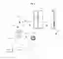
FIG. 4 is a block diagram illustrating an internal structure of an acoustic sensor illustrated in FIG. 1.
Referring to FIG. 4, the acoustic sensor 100 comprises a microphone 110, a sensor unit 120, a communication unit 135, a memory 140, a sound output unit 147, a processor 170, a display 180, and a power supply 190.
The microphone 110 may be provided as a plurality of microphones, and may collect acoustic signals.
The sensor unit 120 may output infrared light, and may receive light corresponding to the output infrared light.
To this end, the sensor unit 120 may comprise a transmitter 120a which outputs infrared light, and a receiver 120b which receives infrared light corresponding to the output infrared light.
The processor 170 may detect the presence of an external object, the movement of an object, and the like, based on a phase difference between the output infrared light and the received infrared light. Particularly, when a thief breaks into the house, the processor 170 may detect the movement of the thief, and may transmit a warning signal to the external server 500 or a mobile terminal (not shown).
Accordingly, by using the acoustic sensor 100, the home security system may be easily provided.
The communication unit 135 may exchange data with an external device.
For example, the communication unit 135 may transmit an acoustic signal, collected by the microphone 110, or data corresponding to the collected acoustic signal, to the external server 500 or the terminal.
Here, the acoustic signal, collected by the microphone 110, may be a failure acoustic signal of the home appliance 200, an operation acoustic signal of the home appliance 200, or a door opening or closing acoustic signal of the home appliance 200.
To this end, the communication unit 135 may perform ZigBee communication, WiFi communication, Bluetooth communication, and the like.
Particularly, the communication unit 135 may transmit location information of calculated touch input to the external server 500 or mobile terminal (not shown) via communication based on Bluetooth Low Energy (BLE) technology.
The memory 140 may store various types of data for the operation of the acoustic sensor 100.
For example, the memory 140 may store data corresponding to a failure acoustic signal of the home appliance 200, data corresponding to an operation acoustic signal of the home appliance 200, or data corresponding to a door opening or closing acoustic signal of the home appliance 200.
The sound output unit 147 may externally output an acoustic signal.
For example, the sound output unit 147 may externally output a sound received through the communication unit 135. Further, in the case where there is a thief in a building, the sound output unit 147 may output a sound corresponding to a warning message.
Alternatively, in the case where there is a need to replace a battery in the power supply 190 of the acoustic sensor 100, the sound output unit 100 may externally output a sound for battery replacement.
The power supply 190 may supply power to each unit in the acoustic sensor 100. To this end, the power supply 190 may be replaced, and may comprise a rechargeable battery.
The processor 170 may control the overall operation of the acoustic sensor 100.
In the case where an acoustic signal, collected by the microphone 110, corresponds to a failure acoustic signal of the home appliance 200, the processor 170 may transmit the collected acoustic signal, or data corresponding to the collected acoustic signal, to the external server 500 or the terminal. Accordingly, failure of the home appliance may be easily diagnosed, thereby improving user convenience in using the home appliance.
In the case where an acoustic signal, collected by the microphone 110, corresponds to the failure acoustic signal of the home appliance 200, the processor 170 may determine that the home appliance 200 has broken down, based on the failure acoustic signal of the home appliance 200.
Further, in the case where an acoustic signal, collected by the microphone 110, corresponds to an operation acoustic signal of the home appliance 200, the processor 170 may transmit the collected acoustic signal, or data corresponding to the collected acoustic signal, to the external server 500 or the terminal.
Moreover, in the case where an acoustic signal, collected by the microphone 110, corresponds to an operation acoustic signal of the home appliance 200, the processor 170 may determine an operation state based on the operation acoustic signal of the home appliance 200.
Further, in the case where the door of the home appliance 200 is opened or closed while the acoustic sensor 100 is attached to the home appliance 200, the processor 170 may transmit a door opening or closing acoustic signal collected by the microphone 110, or data corresponding to the door opening or closing acoustic signal, to the external server 500 or the terminal
In addition, in the case where the acoustic signal, collected by the microphone 110, corresponds to the door opening or closing acoustic signal of the home appliance 200, the processor 170 determines opening or closing of the door of the home appliance 200 based on the door opening or closing acoustic signal.
Further, in the case where an acoustic signal, indicating an operation mode input for a specific home appliance 200, is input through the microphone 110, the processor 170 may enter an operation mode for the home appliance 200.
In the case where the acoustic signal, collected by the microphone 110, is at a reference level or higher, the processor 170 may activate the sensor unit 120, which is in an inactive state, thereby reducing power consumption.
Further, in the case where a moving object is detected based on the output infrared light, output from the sensor unit 120, and the received infrared light, received by the sensor unit 120, the processor 170 may transmit a warning signal to the external server 500 or to the terminal. In this manner, unmanned security may be provided using the acoustic sensor 100.
Moreover, the processor 170 may output sound, received through the communication unit 135, through the sound output unit.
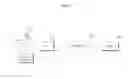
FIG. 5 is a diagram illustrating an example of arrangement of home appliances and acoustic sensors installed in the home appliance system illustrated in FIG. 1.
Referring to FIG. 5, a plurality of home appliances and a plurality of acoustic sensors may be disposed in a home appliance system 50.
FIG. 5 illustrates an example where the refrigerator 200a, the washing machine 200b, the air conditioner 200c, the cooking device 200d, and the cleaner 200e are spaced apart from each other, and a plurality of acoustic sensors 100a to 100e are respectively interposed therebetween.
Specifically, a first acoustic sensor 100a and a second acoustic sensor 100b are disposed near the refrigerator 200a; a third acoustic sensor 100c and a fourth acoustic sensor 100d are disposed near the washing machine 200b; the first acoustic sensor 100a and a fifth acoustic sensor 100e are disposed near the air conditioner 200c; the second acoustic sensor 100b and the third acoustic sensor 100c are disposed near the cooking device 200d; and the fourth acoustic sensor 100d is disposed near the cleaner 200e.
Acoustic signals, collected by the acoustic sensors 100a to 100e, or data corresponding to the collected acoustic signals, may be transmitted to the server 500 through the AP device 400.
FIGS. 6A to 15D are reference diagrams explaining the operation of the acoustic sensors and a server illustrated in FIG. 5.
FIGS. 6A to 6E illustrate an example where failure acoustic signals, output from each home appliance, are transmitted to the server through the acoustic sensors.
As illustrated in FIG. 6A, in the case where failure acoustic signals Sra and Srb are output from the refrigerator 200a, the first acoustic sensor 100a and the second acoustic sensor 100b, which are disposed near the refrigerator 200a, receive the failure acoustic signals Sra and Srb, and may transmit data WSra and WSrb, corresponding to the failure acoustic signals Sra and Srb, to the server 500 through the AP device 400.
As illustrated in FIG. 6B, in the case where failure acoustic signals Swa and Swb are output from the washing machine 200b, the third acoustic sensor 100c and the fourth acoustic sensor 100d, which are disposed near the washing machine 200b, receive the failure acoustic signals Swa and Swb, and may transmit data WSwa and WSwb, corresponding to the failure acoustic signals Swa and Swb, to the server 500 through the AP device 400.
As illustrated in FIG. 6C, in the case where failure acoustic signals Saa and Sab are output from the air conditioner 200c, the first acoustic sensor 100a and the fifth acoustic sensor 100e, which are disposed near the air conditioner 200c, receive the failure acoustic signals Saa and Sab, and may transmit data WSaa and WSab, corresponding to the failure acoustic signals Saa and Sab, to the server 500 through the AP device 400.
As illustrated in FIG. 6D, in the case where failure acoustic signals Sca and Scb are output from the cooking device 200d, the second acoustic sensor 100b and the third acoustic sensor 100c, which are disposed near the cooking device 200d, receive the failure acoustic signals Sca and Scb, and may transmit data WSca and WScb, corresponding to the failure acoustic signals Sca and Scb, to the server 500 through the AP device 400.
As illustrated in FIG. 6E, in the case where failure acoustic signals Srca and Srcb are output from the cleaner 200e, the first acoustic sensor 100a and the fourth acoustic sensor 100d, which are disposed near the air-conditioner 200c, receive the failure acoustic signals Srca and Srcb, and may transmit data WSrca and WSrcb, corresponding to the failure acoustic signals Srca and Srcb, to the server 500 through the AP device 400.
Accordingly, by using the plurality of acoustic sensors 100a to 100e, failure of the home appliances may be easily diagnosed.
In addition to diagnosis of failure, the acoustic sensor 100 may also be used in various applications. For example, the acoustic sensor 100 may be used to monitor an operation state of the home appliances, which will be described below with reference to FIG. 7A and the following figures.
FIG. 7A illustrates an example where a user 900 inputs speech, “attach to the refrigerator”, in front of the refrigerator 200a. In this manner, the acoustic sensor 100, which is attached to the refrigerator 200a, operates in a mode for the refrigerator 200a.
For example, in the case where the door of the refrigerator 200a is opened for an extended period of time, the acoustic sensor 100, which is attached to the refrigerator 200a, collects a warning sound output from the refrigerator 200a, and may transmit the collected warning sound to the server 500 and the like.
In another example, in the case where a notification sound, indicating that the shelf life of food stored in the refrigerator 200a has expired, the acoustic sensor 100 attached to the refrigerator 200a collects the notification sound, and may transmit the collected notification sound to the server 500 and the like.
Further, as illustrated in FIG. 7B, the acoustic sensor 100 attached to the refrigerator 200a may collect a door opening acoustic signal Sopn, and may transmit the collected door opening acoustic signal Sopn to the server 500 and the like.
In addition, as illustrated in FIG. 7C, the acoustic sensor 100 attached to the refrigerator 200a may collect a door closing acoustic signal Scls, and may transmit the collected door closing acoustic signal Scls to the server 500 and the like.
Accordingly, opening or closing of the refrigerator 200a, or an operation state of the refrigerator 200a may be monitored through the server 500 or mobile terminal.
FIG. 8A illustrates an example where a user 900 inputs speech, “attach to the washing machine”, in front of the washing machine 200b. In this manner, the acoustic sensor 100, which is attached to the washing machine 200b, operates in a mode for the washing machine 200b.
For example, the acoustic sensor 100 attached to the washing machine 200b may collect a warning sound, which is output from the washing machine 200b to indicate laundry is left in the machine, and may transmit the collected warning sound, indicating laundry is left, to the server 500 and the like.
As illustrated in FIG. 8B, the acoustic sensor 100 attached to the washing machine 200b may collect vibrations of the washing machine 200b, an acoustic signal produced by the vibrations, or operation acoustic signals Swa1 and Swab1, and may transmit the collected vibrations or signals to the server 500 and the like.
Accordingly, the operation state of the washing machine 200b may be monitored through the server 500 or mobile terminal.
FIG. 9A illustrates an example where a user 900 inputs speech, “attach to the air conditioner”, in front of the air conditioner 200c. In this manner, the acoustic sensor 100, which is attached to the air conditioner 200c, operates in a mode for the air conditioner 200c.
For example, in the case where a filter replacement notification sound is generated, the acoustic sensor 100 attached to the air conditioner 200c collects the filter replacement notification sound, and may transmit the collected filter replacement notification sound to the server 500 and the like.
As illustrated in FIG. 9B, the acoustic sensor 100 attached to the air conditioner 200c may collect operation acoustic signals Saa1 and Saab1 of the air conditioner 200c, and may transmit the collected signals to the server 500 and the like.
Accordingly, the operation state of the air conditioner 200c may be monitored through the server 500 or mobile terminal.
FIG. 10A illustrates an example where a user 900 inputs speech, “attach to the cooking device”, in front of the cooking device 200d. In this manner, the acoustic sensor 100, which is attached to the cooking device 200d, operates in a mode for the cooking device 200d.
For example, the acoustic sensor 100 attached to the cooking device 200d may collect an operation completion sound of the cooking device 200d, and may transmit the collected operation completion notification sound to the server 500 and the like.
Further, as illustrated in 10B, the acoustic sensor 100 attached to the cooking device 200d may collect operation acoustic signals Sca1 and Scb1 of the cooking device 200d, and may transmit the collected signals to the server 500 and the like.
Accordingly, the operation state of the cooking device 200d may be monitored through the server 500 or mobile terminal.
FIG. 11A illustrates an example where a user 900 inputs speech, “attach to the cleaner”, in front of the cleaner 200e. In this manner, the acoustic sensor 100, which is attached to the cleaner 200e, operates in a mode for the cleaner 200e.
For example, the acoustic sensor 100 attached to the cleaner 200e may collect a battery replacement notification sound, a battery charging notification sound, and the like, and may transmit the collected sounds to the server 500 and the like.
Further, as illustrated in FIG. 11B, the acoustic sensor 100 attached to the cleaner 200e may collect operation acoustic signals Scra1 and Scrb1 of the cleaner 200e, and may transmit the collected signals to the server 500 and the like.
Accordingly, the operation state of the cleaner 200e may be monitored through the server 500 or mobile terminal.
FIGS. 12A to 12E illustrate an example of an unmanned security mode using acoustic sensors.
FIG. 12A illustrate an example where nobody is in a house 10.
As illustrated in FIG. 12B, in the case where a thief 907 breaks into the house 10, the acoustic sensors 100a to 100c collect acoustic signals generated by the thief 907, and may transmit data Wsch1 to Wsch3, corresponding to the collected acoustic signals, to the server 500 through the AP device 400.
Accordingly, the server 500 may determine that the thief 907 has broken into the house 10.
In the case where the collected acoustic signal is at a reference level or higher, the acoustic sensors 100a to 100c may activate the sensor unit 120, which is in an inactive state, for more accurate determination.
That is, the acoustic sensors 100a to 100c may activate the sensor unit 120, which may output infrared light, by transmitting activation signals Saca, Sacb, and Sacc, respectively.
As illustrated in FIG. 12D, in the case where the thief 907 moves around in the house 10, the sensor unit 120 may transmit detection data WSaca, WSacb, and WSacc to the server 500 through the AP device 400, based on a phase difference between the output infrared light and the received infrared light.
Accordingly, the server 500 may determine that the thief 907 has broken into the house 10.
Further, in response to the determination that the thief 907 has broken into the house 10, the server 500 may transmit a warning signal to the acoustic sensors 100a to 100c, and the acoustic sensors 100a to 100c may output the received warning signal through the sound output unit.
FIG. 13 is a diagram illustrating an example where a plurality of acoustic sensors are placed in the house.
As illustrated in FIG. 13, the plurality of acoustic sensors 100a to 100g may be positioned all over the house 10.
By using the acoustic sensors placed all over the house 10, baby care, child care, silver care, home care, care of electric power, and the like may be provided.
For example, when a baby 1102 is crying as illustrated in (a) of FIG. 14, the acoustic sensor 100 collects the crying sound, and may transmit the collected sound to the server 500 or the mobile terminal (not shown). Accordingly, it may be recognized by the server 500 or the mobile terminal (not shown) that the baby 1102 is crying, such that baby care may be provided.
In the case where a child 1105 is crying as illustrated in (b) of FIG. 14, the acoustic sensor 100 collects the crying sound, and may transmit the collected sound to the server 500 or the mobile terminal (not shown). Accordingly, it may be recognized by the server 500 or the mobile terminal (not shown) that the baby 1102 is crying, such that baby care may be provided.
Further, in the case where an elderly man 1107 collapsed as illustrated in (c) of FIG. 14, the acoustic sensor 100 collects the collapsing sound, and may transmit the collected sound to the server 500 or the mobile terminal (not shown). Accordingly, it may be recognized by the server 500 or the mobile terminal (not shown) that the elderly man 1107 collapsed at home, such that silver care may be provided.
In addition, in the case where a thief 1259 breaks in as illustrated in (d) of FIG. 14, the acoustic sensor 100 collects the sound of the thief, and may transmit the collected sound to the server 500 or the mobile terminal (not shown). Accordingly, it may be recognized by the server 500 or the mobile terminal (not shown) that the thief 1259 has broken into the house, such that home care may be provided.
Moreover, in the case where a fire 1450 breaks out as illustrated in (e) of FIG. 14, the acoustic sensor 100 collects the sound of fire, and may transmit the collected sound to the server 500 or the mobile terminal (not shown). Accordingly, it may be recognized by the server 500 or the mobile terminal (not shown) that a fire has broken out in the house.
Further, in the case where TV 1108 is turned on as illustrated in (f) of FIG. 14, the acoustic sensor 100 collects the sound of TV, and may transmit the collected sound to the server 500 or the mobile terminal (not shown). Accordingly, it may be recognized by the server 500 and the mobile terminal (not shown) that the TV 1108 is turned on in the house.
The acoustic sensor 100 may output the received sound through the sound output unit 147.
In the case where the baby 1102 is crying as illustrated in FIG. 15A, the acoustic sensor 100 may output, through the sound output unit 147, speech 1630 such as “Don't cry, my baby. Mommy will be right back”, thereby soothing the crying baby 1102.
Further, in the case where the child 1105 is crying as illustrated in FIG. 15B, the acoustic sensor 100 may output, through the sound output unit 147, speech 1730 such as “Don't cry my daughter. Mommy will be right back”, thereby soothing the crying child 1105.
FIG. 15C illustrates an example where a cooking pot boils over during the operation of the cooking device 1800 which is a gas cooking device. The acoustic sensor 100 collects an acoustic signal of the boiling over, and may transmit the collected signal to the server 500 and the like.
In addition, as illustrated in FIG. 15D, the acoustic sensor 100 may output, to the sound output unit 147, a notification message 1835, which is received from an external source or generated autonomously, to notify danger of fire outbreak or gas leakage.
The server 500 may transmit a message of danger notification to a mobile terminal and the like, and the mobile terminal 600 may output a notification message 1830, received from the server 500, to notify the danger of fire outbreak or gas leakage, such that home care may be provided by using the acoustic sensor 100.
As is apparent from the above description, the present invention has the following effects.
According to an exemplary embodiment of the present invention, the acoustic sensor comprises a communication unit, a microphone to collect an acoustic signal, a memory to store a failure acoustic signal of a home appliance, and a processor, wherein in response to the acoustic signal, collected by the microphone, corresponding to the failure acoustic signal of the home appliance, the processor transmits the collected acoustic signal, or data corresponding to the collected acoustic signal, to an external server or a terminal. Accordingly, by using the acoustic sensor, failure of the home appliance may be easily diagnosed.
In this manner, user convenience in using the home appliance may be improved.
Further, in response to the acoustic signal, collected by the microphone, corresponding to an operation acoustic signal of the home appliance, the acoustic sensor may transmit the collected acoustic signal, or data corresponding to the collected acoustic signal, to the external server or the terminal. Accordingly, an operation state of the home appliance may be easily identified.
In addition, in response to the acoustic signal, collected by the microphone, corresponding to a door opening or closing acoustic signal of the home appliance, the acoustic sensor may transmit the collected acoustic signal, or data corresponding to the door opening or closing acoustic signal, to the external server or the terminal. Accordingly, it may be easily identified whether the door of the home appliance is opened or closed.
The acoustic sensor may further comprise a sensor unit to output and receive infrared light, wherein in response to a moving object being detected, the acoustic sensor may transmit a warning signal to the external server or the terminal by using the sensor unit. In this manner, the acoustic sensor may be used as an unmanned security system in a building.
Further, in response to the acoustic signal, collected by the microphone, being at a reference level or higher, the acoustic sensor may activate the sensor unit which is in an inactive state, thereby reducing power consumption.
According to an exemplary embodiment of the present invention, the home appliance system comprises a home appliance, an acoustic sensor attached to the home appliance or disposed near the home appliance, and a server, wherein in response to a failure acoustic signal of the home appliance being collected by the acoustic sensor, the server receives the failure acoustic signal of the home appliance, or data corresponding to the failure acoustic signal of the home appliance, from the acoustic sensor. Accordingly, by using the acoustic sensor, failure of the home appliance may be easily diagnosed.
In this manner, user convenience in using the home appliance may be improved.
As described above, the acoustic sensors and the home appliance system comprising the same are not limited to the configuration and method of the above-described embodiments, and all or some of the above embodiments may be selectively combined with each other to enable various modifications thereof.
The operation methods of the terminal or the home appliance according to the present invention may be implemented as processor-readable code that can be written on a processor-readable recording medium comprised in the terminal or the home appliance. The processor-readable recording medium may be any type of recording device in which data is stored in a processor-readable manner. Examples of the processor-readable recording medium comprise a Read Only Memory (ROM), a Random Access Memory (RAM), a Compact Disk Read Only Memory (CD-ROM), a magnetic tape, a floppy disk, an optical data storage device, etc. In addition, the processor-readable recording medium may be a carrier wave, e.g., data transmission over the Internet. In addition, the processor-readable recording medium can be distributed over a plurality of computer systems connected to a network such that processor-readable code is written thereto and executed therefrom in a distribution manner.
It will be apparent that, although the preferred embodiments have been shown and described above, the present invention is not limited to the above-described specific embodiments, and various modifications and variations can be made by those skilled in the art without departing from the gist of the appended claims. Thus, it is intended that the modifications and variations should not be understood independently of the technical spirit or prospect of the present invention.
Claims
What is claimed is:1. An acoustic sensor comprising:
a communication unit;
a microphone to collect an acoustic signal;
a memory to store a failure acoustic signal of a home appliance; and
a processor, wherein in response to the acoustic signal, collected by the microphone, corresponding to the failure acoustic signal of the home appliance, the processor transmits the collected acoustic signal, or data corresponding to the collected acoustic signal, to an external server or a terminal.
2. The acoustic sensor of claim 1, wherein in response to the acoustic signal, collected by the microphone, corresponding to the failure acoustic signal of the home appliance, the processor determines that the home appliance has broken down, based on the failure acoustic signal of the home appliance.
3. The acoustic sensor of claim 1, wherein in response to the acoustic signal, collected by the microphone, corresponding to an operation acoustic signal of the home appliance, the processor transmits the collected acoustic signal, or data corresponding to the collected acoustic signal, to the external server or the terminal.
4. The acoustic sensor of claim 3, wherein in response to the acoustic signal, collected by the microphone, corresponding to the operation acoustic signal of the home appliance, the processor determines an operation state of the home appliance based on the operation acoustic signal of the home appliance.
5. The acoustic sensor of claim 1, wherein when a door of the home appliance is opened or closed while the acoustic sensor is attached to the home appliance, the processor transmits a door opening or closing acoustic signal, collected by the microphone, or data corresponding to the door opening or closing acoustic signal, to the external server or the terminal.
6. The acoustic sensor of claim 5, wherein in response to the acoustic signal, collected by the microphone, corresponding to the door opening or closing acoustic signal of the home appliance, the processor determines opening or closing of the door of the home appliance based on the door opening or closing acoustic signal of the home appliance.
7. The acoustic sensor of claim 1, wherein in response to an acoustic signal, indicating an operation mode input for a home appliance, being input through the microphone, the processor enters the operation mode for the home appliance.
8. The acoustic sensor of claim 1, wherein the processor further comprises a sensor unit to output infrared light and receive light corresponding to the output infrared light,
wherein in response to the acoustic signal, collected by the microphone, being at a reference level or higher, the processor activates the sensor unit which is in an inactive state.
9. The acoustic sensor of claim 8, wherein in response to a moving object being detected, the processor transmits a warning signal to the external server or the terminal based on the output infrared light, which is output from the sensor unit, and the received infrared light which is received by the sensor unit.
10. The acoustic sensor of claim 1, further comprising a sound output unit,
wherein the processor outputs a sound, received by the communication unit, through the sound output unit.
11. A home appliance system comprising:
a home appliance;
an acoustic sensor attached to the home appliance or disposed near the home appliance; and
a server, wherein in response to a failure acoustic signal of the home appliance being collected by the acoustic sensor, the server receives the failure acoustic signal of the home appliance, or data corresponding to the failure acoustic signal of the home appliance, from the acoustic sensor.
12. The home appliance system of claim 11, wherein in response to the acoustic signal, collected by the acoustic sensor, corresponding to the failure acoustic signal of the home appliance, the server determines that the home appliance has broken down, based on the failure acoustic signal of the home appliance.
13. The home appliance system of claim 11, wherein in response to the acoustic signal, collected by the acoustic sensor, corresponding to an operation acoustic signal of the home appliance, the server receives the collected acoustic signal, or data corresponding to the collected acoustic signal, from the acoustic sensor.
14. The home appliance system of claim 13, wherein in response to the acoustic signal, collected by the acoustic sensor, corresponding to the operation acoustic signal of the home appliance, the server determines an operation state of the home appliance based on the operation acoustic signal of the home appliance.
15. The home appliance system of claim 11, wherein when a door of the home appliance is opened or closed while the acoustic sensor is attached to the home appliance, the server receives a door opening or closing acoustic signal, collected by the acoustic sensor, or data corresponding to the door opening or closing acoustic signal, from the acoustic sensor.
16. The home appliance system of claim 15, wherein in response to the acoustic signal, collected by the acoustic sensor, corresponding to the door opening or closing acoustic signal of the home appliance, the server determines opening or closing of the door of the home appliance based on the door opening or closing acoustic signal of the home appliance.
17. The home appliance system of claim 11, wherein in response to an acoustic signal, indicating an operation mode input for a home appliance, being input to the microphone, the acoustic sensor enters the operation mode for the specific home appliance.
18. The home appliance system of claim 11, wherein the acoustic sensor outputs infrared light and receives light corresponding to the output infrared light,
wherein in response to the acoustic signal, collected by the microphone, being at a reference level or higher, the acoustic sensor activates the sensor which is in an inactive state.
19. The home appliance system of claim 18, wherein in response to a moving object being detected, the server receives a warning signal from the acoustic sensor based on the output infrared light, which is output from the acoustic sensor, and the received infrared light, which is received by the acoustic sensor.
20. The home appliance system of claim 11, wherein the server transmits a sound to the acoustic sensor,
wherein the acoustic sensor outputs the sound, received by the server, through the sound output unit.
Images & Drawings included:


Sources:
- United States Patent and Trademark Office - verify current appl. status at the USPTO↗
Recent applications in this class:
- » 20220214211 2022-07-07
Acoustic sensor assembly and method of sensing sound using the same - » 20220090957 2022-03-24
Infrasound detector with force transducer for negative feedback or calibration - » 20210063237 2021-03-04
Vibration detection instrument assembly and method of assembling a vibration detection instrument assembly - » 20190212188 2019-07-11
Method and system for monitoring rotor blades of a turbomachine using blade tip timing (BTT) - » 20170234725 2017-08-17
SENSOR ELEMENT, METHOD OF MANUFACTURING SENSOR ELEMENT, SENSOR, ELECTRONIC APPARATUS, AND MOVING OBJECT - » 20140096612 2014-04-10
SYSTEM AND METHOD FOR DETECTING VIBRATION - » 20130197350 2013-08-01
Radiation force balance calibrator - » 20130139597 2013-06-06
Wavelength division sensing RF vibrometer for accurate measurement of complex vibrations - » 20120304775 2012-12-06
Detection of anomalous movement in a reciprocating device - » 20120299440 2012-11-29
Devices comprising nanotubes or nanowires having alterable characteristics and related methods
Recent applications for this Assignee:
- » 20250294563 2025-09-18
METHOD AND DEVICE FOR INCREASING UPLINK CONTROL RESOURCES IN WIRELESS COMMUNICATION SYSTEM - » 20250294548 2025-09-18
METHOD AND DEVICE FOR TRANSMITTING/RECEIVING SIGNAL IN WIRELESS COMMUNICATION SYSTEM - » 20250294465 2025-09-18
METHOD AND APPARATUS FOR PERFORMING UPLINK TRANSMISSION IN WIRELESS COMMUNICATION SYSTEM - » 20250294425 2025-09-18
METHOD AND APPARATUS FOR MOBILITY BASED ON HEIGHT IN A WIRELESS COMMUNICATION SYSTEM - » 20250294206 2025-09-18
DISPLAY DEVICE AND CONTENT SHARING METHOD FOR SHARING CONTENT WITH EXTERNAL DISPLAY DEVICE - » 20250294153 2025-09-18
METHOD FOR CODING IMAGE ON BASIS OF SELECTIVE TRANSFORM AND DEVICE THEREFOR - » 20250294150 2025-09-18
METHOD AND APPARATUS FOR CABAC-BASED ENTROPY CODING - » 20250294136 2025-09-18
AFFINE MOTION PREDICTION-BASED IMAGE DECODING METHOD AND APPARATUS USING AFFINE MVP CANDIDATE LIST IN IMAGE CODING SYSTEM - » 20250292745 2025-09-18
SINK DEVICE AND OPERATING METHOD THEREOF - » 20250291418 2025-09-18
ELECTRONIC DEVICE HAVING TOUCH PAD REGION AND KEYBOARD