Optical lens
US20170293107A1
2017-10-12
15/093,762
2016-04-08
✅ Patent granted
US 10,551,593 B2
2020-02-04
-
-
William R Alexander
JCIPRNET
2037-12-15
Abstract:
An optical lens including a first lens group and a second lens group is provided. The first lens group is arranged between a magnified side and a minified side. The first lens group includes a lens closest to the magnified side. A refractive power of the lens is negative, and at least one surface of the lens is an aspherical surface. The second lens group is arranged between the first lens group and the minified side. A distance between the first lens group and the second lens group is smaller than 0.7 millimeter. The optical lens is complied with conditions of 0.53<EFL/IH<0.7, FOV≧150 degrees, and F≦2.8, where EFL is an effective focal length, IH is an image height on an imaging plane at the minified side, FOV is a maximum field of view, and F is f-number.
Assignee:
- YOUNG OPTICS INC. 259 🇹🇼 Hsinchu, Taiwan
Applicant:
Interested in similar patents?
Get notified when new applications in this technology area are published.
Classification:
G02B13/18 » CPC further
Optical objectives specially designed for the purposes specified below with lenses having one or more non-spherical faces, e.g. for reducing geometrical aberration
G02B27/00 IPC
Optical systems or apparatus not provided for by any of the groups -
G02B27/0025 » CPC further
Optical systems or apparatus not provided for by any of the groups - for optical correction, e.g. distorsion, aberration
G02B9/64 » CPC main
Optical objectives characterised both by the number of the components and their arrangements according to their sign, i.e. + or - having more than six components
Description
BACKGROUND OF THE INVENTION
Field of the Invention
The invention relates to an optical device, and particularly relates to an optical lens.
Description of Related Art
In recent years, along with development of technology, all kinds of demands for image capturing are gradually increasing. For example, the demands for lenses having a wide field of view (FOV), such as super wide-angle lenses or fisheye lenses, are gradually increasing in, for example, products of car lenses and security surveillance cameras. However, as FOV gradually increases, optical aberration are also rapidly generated, such that optical design of the lenses becomes more difficult. In order to abate the optical aberration, it is common to increase the number of lenses or adopt aspherical lenses in related arts. As a result, the manufacture of the lenses become more difficult, and thus the cost of the lenses is also increased. Therefore, how to fabricate a lens having the characteristics of a wide FOV, miniaturization, a low cost, a high resolution, a large aperture, a short total track length (TTL) and capable of providing good optical quality is an important issue for those technicians of the field.
SUMMARY OF THE INVENTION
The invention relates to an optical lens having a wide field of view (FOV) angle, a large aperture, a short total track length (TTL), and capable of providing good optical quality.
An embodiment of the invention provides an optical lens including a first lens group and a second lens group. The first lens group is arranged between a magnified side and a minified side. The first lens group includes a first lens, a second lens, a third lens and a fourth lens sequentially arranged from the magnified side to the minified side. The first lens is a lens of the first lens group closest to the magnified side. The first lens is a biconcave lens, and at least one surface of the first lens is an aspherical surface. The second lens group is arranged between the first lens group and the minified side. The second lens group includes a fifth lens, a sixth lens, and a seventh lens sequentially arranged from the magnified side to the minified side. The optical lens is complied with a condition of 0.53<EFL/IH<0.7, where EFL is an effective focal length of the optical lens, and IH is an image height on an imaging plane of the optical lens at the minified side.
Another embodiment of the invention provides an optical lens including a first lens group and a second lens group. The first lens group is arranged between a magnified side and a minified side. The first lens group includes a first lens closest to the magnified side. A refractive power of the first lens is negative, and at least one surface of the first lens is an aspherical surface. The second lens group is arranged between the first lens group and the minified side. A distance between the first lens group and the second lens group is smaller than 0.7 millimeter. The optical lens is complied with conditions of FOV≧150 degrees and F≦2.8, where FOV is a maximum field of view of the optical lens, and F is f-number.
According to the above descriptions, in the embodiments of the invention, the design of the optical lens is complied with the predetermined conditions and standards, so that the optical lens has a FOV angle, a large aperture, a short TTL, and is capable of providing good optical quality.
In order to make the aforementioned and other features and advantages of the invention comprehensible, several exemplary embodiments accompanied with figures are described in detail below.
BRIEF DESCRIPTION OF THE DRAWINGS
The accompanying drawings are included to provide a further understanding of the invention, and are incorporated in and constitute a part of this specification. The drawings illustrate embodiments of the invention and, together with the description, serve to explain the principles of the invention.
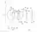
FIG. 1 is a schematic diagram of an optical lens according to an embodiment of the invention.
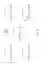
FIG. 2 to FIG. 4 are imaging optical simulation data plots of the optical lens of FIG. 1.
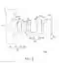
FIG. 5 is a schematic diagram of an optical lens according to another embodiment of the invention.
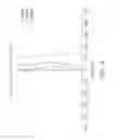
FIG. 6 to FIG. 8 are imaging optical simulation data plots of the optical lens of FIG. 5.
DESCRIPTION OF EMBODIMENTS
The present invention will now be described more fully with reference to the accompanying drawings, in which exemplary embodiments of the invention are shown. The terms used herein such as “above”, “below”, “front”, “back”, “left” and “right” are for the purpose of describing directions in the figures only and are not intended to be limiting of the invention.
FIG. 1 is a schematic diagram of an optical lens according to an embodiment of the invention. Referring to FIG. 1, the optical lens 100 of the present embodiment is located between a magnified side OS and a minified side IS. The optical lens 100 includes a first lens group 110, a second lens group 120, an infrared filter 130 and a glass cover 140. The first lens group 110 is arranged between the magnified side OS and the second lens group 120. The second lens group 120 is arranged between the first lens group 110 and the minified side IS, an aperture S is arranged between the first lens group 110 and the second lens group 120, and the first lens group 110 and the second lens group 120 are arranged along an optical axis A of the optical lens 100. In the present embodiment, a distance D between the first lens group 110 and the second lens group 120 on the optical axis A of the optical lens 100 is smaller than 0.7 millimeter.
In the present embodiment, the lens group 110 includes a first lens (L1) 112, a second lens (L2) 114, a third lens (L3) 116 and a fourth lens (L4) 118 sequentially arranged from the magnified side OS to the minified side IS, and refractive powers thereof are respectively negative, negative, positive and positive. The first lens 112 is a lens closest to the magnified side OS in the first lens group 110. The second lens group 120 includes a fifth lens (L5) 122, a sixth lens (L6) 124 and a seventh lens (L7) 126 sequentially arranged from the magnified side OS to the minified side IS, and refractive powers thereof are respectively negative, positive and positive. In the present embodiment, the first lens 112, the second lens 114, the third lens 116 and the seventh lens 126 are plastic lenses, and the fourth lens 118, the fifth lens 122, and the sixth lens 126 are glass lenses.
In the present embodiment, the first lens 112, the second lens 114, the third lens 116 and the seventh lens 226 are aspherical lenses. The first lens is a biconcave lens, and at least one surface of the first lens is an aspherical surface. In the present embodiment, two surfaces S1 and S2 of the first lens are aspherical surfaces. The surface S1 of the first lens 112 facing to the magnified side OS has an inflection property. As shown in FIG. 1, the surface S1 of the first lens 112 is an aspherical surface having at least one inflection point, and the inflection, for example, occurs where the curvature equals zero. In the present embodiment, a surface S3 of the second lens 114 facing to the magnified side OS is a convex surface. The third lens 116 is a concavo-convex lens. The fifth lens 122 and the sixth lens 124 construct a cemented lens for balancing chromatic aberration of the optical lens 100 including axial color and lateral color, but the arrangement purpose of the cemented lens is not intended to limit the invention.
In the present embodiment, a glass cover 140 and an image sensor can be set at the minified side IS, and the imaging plane thereof is indicated as 150. The glass cover 140 is arranged between the second lens group 120 and the imaging plane 150. An infrared filter 130 can be set between the seventh lens 126 and the glass cover 140. The optical lens 100 produces images on the imaging plane 150.
Specific data of each of the lenses in the optical lens 100 of FIG. 1 is listed in the following table 1.
| TABLE ONE | |||||
| Radius of | |||||
| Surface | curvature | Gap | Refractive | Abbe | |
| No. | (mm) | (mm) | index | number | Remark |
| S1 | −10.925 | 0.954 | 1.531 | 55.754 | L1 |
| S2 | 3.454 | 1.863 | |||
| S3 | 43.088 | 0.551 | 1.531 | 55.754 | L2 |
| S4 | 2.118 | 0.588 | |||
| S5 | 2.731 | 1.013 | 1.636 | 23.972 | L3 |
| S6 | 3.285 | 0.227 | |||
| S7 | 4.782 | 1.973 | 1.847 | 23.778 | L4 |
| S8 | −6.916 | 0.547 | |||
| S9 | −8.900 | 0.612 | 1.923 | 18.897 | L5 |
| S10 | 3.500 | 1.819 | 1.697 | 55.532 | L6 |
| S11 | −3.912 | 0.118 | |||
| S12 | 5.198 | 1.974 | 1.531 | 55.754 | L7 |
| S13 | −7.776 | 2.761 | |||
| S14 | Infinity | 0.8 | 1.517 | 64.167 | |
| S15 | Infinity | 2.6 | |||
| S16 | Infinity | 0.4 | 1.517 | 64.167 | |
| 150 | Imaging plane | ||||
In the table 1, the gap refers to a straight-line distance between adjacent surfaces along the optical axis A. For example, a gap of the surface S1 refers to a straight-line distance between the surface S1 and the surface S2 along the optical axis A. The table 1 records thickness, refractive indexes and Abbe numbers of each of the lenses, and a remark column records the corresponding lenses. Moreover, in the table 1, the surfaces S1 and S2 are two surfaces of the first lens 112, the surfaces S3 and S4 are two surfaces of the second lens 114 et cetera. In the present embodiment, the surfaces S1 to S6, S12 and S13 are aspherical surfaces, which can be represented by the following equation (4):
Z = cr 2 1 + 1 - ( 1 + k ) c 2 r 2 + A 2 r 2 + A 4 r 4 + A 6 r 6 + A 8 r 8 + A 10 r 10 + A 12 r 12 + … ( 4 )
In the equation (4), Z is a sag along the direction of the optical axis A, c is a reciprocal of a radius of an osculating sphere, i.e., a reciprocal of the radius of curvature close to the optical axis A (for example, the radius of curvature of the surfaces S1 to S6 and S12 to S13. k is a conic coefficient, r is a height of the aspherical surface, i.e., a height from a lens center to a lens edge, and A2, A4, A6, A8, A10, and A12 . . . are aspheric coefficients, and in the present embodiment, the aspheric coefficients A2 and the conic coefficient k is 0. The following table 2 lists parameter values of the surfaces S1 to S6 and S12 to S13.
| TABLE 2 | |||||
| A4 | A6 | A8 | A10 | A12 | |
| S1 | 4.8636E−03 | −1.8355E−04 | 4.4088E−06 | −5.7877E−08 | 3.3790E−10 |
| S2 | −9.8072E−03 | 1.5879E−03 | −3.0966E−05 | −5.7476E−06 | 0 |
| S3 | 6.3618E−03 | −2.0731E−03 | 1.9281E−04 | −6.1805E−06 | 0 |
| S4 | 4.2738E−02 | −1.3721E−02 | 8.3572E−04 | 3.8572E−05 | 0 |
| S5 | 7.1455E−03 | −4.4218E−03 | 6.5133E−04 | −8.8262E−05 | 0 |
| S6 | −5.6176E−04 | 1.4672E−03 | −1.0803E−03 | 3.9596E−05 | 0 |
| S12 | −1.9814E−04 | −1.4252E−04 | 1.1859E−05 | −2.3742E−07 | 0 |
| S13 | 5.4287E−03 | −5.2974E−04 | 2.5065E−05 | −4.2085E−08 | 0 |
In the present embodiment, the optical lens 100 is complied with at least one of the following conditions (1) to (7):
0.53<EFL/IH<0.7 (1)
0.45<EFL/BFL<0.7 (2)
0.15<BFL/TTL<0.26 (3)
TTL<17 millimeters (4)
FOV≧150 degrees (5)
F≦2.8 (6)
CRA<12 degrees (7)
where FOV is a field of view of the optical lens 100 or a maximum field of view, TTL is a total track length of the optical lens 100, which is a distance between the surface S1 of the first lens 112 and an imaging plane 150 of the optical lens at the minified side IS along the optical axis A, IH is an image height on the imaging plane 150 of the optical lens 100 at the minified side IS, F is a f-number, EFL is an effective focal length of the optical lens 100, BFL is a back focal length of the optical lens 110, which is a distance between a surface S13 of the seventh lens 126 and the imaging plane 150 of the optical lens 100 at the minified side IS along the optical axis A, and CRA is a chief ray angle of the optical lens 100. In this way, the optical lens 100 complied with at least one of the aforementioned conditions may have good optical imaging quality and good optical characteristics.
More specifically, in the optical lens 100 of the present embodiment, the F-number (Fno) is 2.0, the FOV is 160.2 degrees, and the total track length TTL is 15.8 millimeters. The effective focal length EFL is 1.80 millimeters, the image height on the imaging plane is 3.09 millimeters, and a ratio between the effective focal length and the image height on the imaging plane is EFL/IH=0.583. A ratio between the effective focal length and the back focal length is EFL/BFL=0.504. The chief ray angle CRA is 7.79 degrees.
It should be noticed that reference numbers of the components and a part of contents of the aforementioned embodiment are also used in the following embodiment, where the same reference numbers denote the same or like components, and descriptions of the same technical contents are omitted. The aforementioned embodiment can be referred for descriptions of the omitted parts, and detailed descriptions thereof are not repeated in the following embodiment.
FIG. 5 is a schematic diagram of an optical lens according to another embodiment of the invention. Referring to FIG. 1 and FIG. 5, a main difference between the optical lens 200 of the present embodiment and the optical lens 100 is that a surface S3 of the second lens 214 facing to the magnified side OS is a concave surface.
Specific data of each of the lenses in the optical lens 200 of FIG. 5 is listed in the following table 3.
| TABLE 3 | |||||
| Radius of | |||||
| Surface | curvature | Gap | Refractive | Abbe | |
| No. | (mm) | (mm) | index | number | Remark |
| S1 | −7.197 | 1.000 | 1.525 | 56.282 | L1 |
| S2 | 3.378 | 1.754 | |||
| S3 | −6.312 | 0.550 | 1.525 | 56.282 | L2 |
| S4 | 16.978 | 0.413 | |||
| S5 | 4.690 | 1.334 | 1.636 | 23.972 | L3 |
| S6 | 35.398 | 0.236 | |||
| S7 | −14.353 | 1.614 | 1.847 | 23.778 | L4 |
| S8 | −3.719 | 0.685 | |||
| S9 | −11.729 | 0.600 | 1.923 | 18.897 | L5 |
| S10 | 3.300 | 2.357 | 1.697 | 55.532 | L6 |
| S11 | −3.617 | 0.100 | |||
| S12 | 6.402 | 1.593 | 1.525 | 56.282 | L7 |
| S13 | −44.653 | 0.160 | |||
| S14 | Infinity | 0.4 | 1.517 | 64.167 | |
| S15 | Infinity | 2.6 | |||
| S16 | Infinity | 0.4 | 1.517 | 64.167 | |
| 250 | Imaging plane | ||||
Interpretation of various optical parameters and data in the table 3 may refer to related description of the table 1. In the present embodiment, the surfaces S1 to S6, S12 and S13 are aspherical surfaces, which can be represented by the aforementioned equation (4). The following table 4 lists parameter values of the surfaces S1 to S6 and S12 to S13. In the present embodiment, the coefficient A2 is 0.
| TABLE 4 | ||||||
| k | A4 | A6 | A8 | A10 | A12 | |
| S1 | 0 | 5.4698E−03 | −1.7776E−04 | 4.3759E−06 | −6.0374E−08 | 4.1562E−10 |
| S2 | 0 | −2.1379E−02 | 2.7285E−03 | −1.2935E−04 | 5.4697E−07 | 1.3570E−10 |
| S3 | 2.37061789 | 2.2603E−02 | −3.5598E−03 | 3.0887E−04 | −8.3077E−06 | 9.9753E−09 |
| S4 | 21.10491474 | 1.0533E−01 | −2.0386E−02 | −1.6181E−04 | 3.1738E−04 | −4.1357E−08 |
| S5 | 3.152173374 | 4.3596E−02 | −1.9481E−02 | 3.3988E−03 | −4.8219E−04 | 4.9754E−07 |
| S6 | 98.98992138 | 1.7986E−02 | −4.3751E−03 | 1.6230E−03 | −5.2264E−04 | 2.7538E−07 |
| S12 | −0.101293929 | 1.4683E−03 | −1.0365E−03 | 1.4882E−04 | −6.2329E−06 | −4.5682E−09 |
| S13 | −98.98823176 | 6.0123E−03 | −1.9094E−03 | 1.9656E−04 | −6.4506E−06 | 7.6247E−10 |
According to the above description, in the optical lens 200 of the present embodiment, the F-number (Fno) is 2.0, the FOV is 150 degrees, and the total track length TTL is 16.5 millimeters. The effective focal length EFL is 1.94 millimeters, the image height on the imaging plane is 2.84 millimeters, and a ratio between the effective focal length and the image height on the imaging plane is EFL/IH=0.683. A ratio between the effective focal length and the back focal length is EFL/BFL=0.544. The chief ray angle CRA is 7.79 degrees.
FIG. 2 to FIG. 4 and FIG. 6 to FIG. 8 are imaging optical simulation data plots of the optical lenses of FIG. 1 and FIG. 5, where FIG. 2 and FIG. 6 are transverse ray fan plots, in which an X-axis represents positions where lights passes through the aperture S, and a Y-axis represents positions where the lights are projected on the imaging plane (for example, the imaging plane 150 or 250). A color light with a red light with a wavelength of 650 nanometers (nm), a green light with a wavelength of 550 nm, and a blue light with a wavelength of 470 nm are taken as reference wavebands to perform simulation. FIG. 3 and FIG. 7 are spot diagrams simulated by the red light with the wavelength of 650 nm, the green light with the wavelength of 550 nm, and the blue light with the wavelength of 470 nm. FIG. 4 and FIG. 8 respectively illustrate field curvatures are simulated by the red light with the wavelength of 650 nm, the green light with the wavelength of 550 nm, and the blue light with the wavelength of 470 mn. Since the diagrams of the aforementioned figures are all within a standard range, the optical lens 100 and 200 of the embodiments may provide good imaging quality under conditions of a wide FOV, miniaturization, a thinning appearance, a high resolution, a short TTL, a large aperture, a low distortion, etc.
In summary, in the embodiments of the invention, the design of the optical lens is complied with the predetermined conditions and standards, so that the optical lens of the embodiments may provide good imaging quality under conditions of a wide FOV, miniaturization, a thinning appearance, a high resolution, a short TTL, a large aperture, a low distortion, etc.
It will be apparent to those skilled in the art that various modifications and variations can be made to the structure of the embodiments without departing from the scope or spirit of the invention. In view of the foregoing, it is intended that the invention cover modifications and variations of this invention provided they fall within the scope of the following claims and their equivalents.
Claims
What is claimed is:1. An optical lens, comprising:
a first lens group, arranged between a magnified side and a minified side, and comprising at least a first lens, a second lens, a third lens and a fourth lens sequentially arranged from the magnified side to the minified side, wherein the first lens is a lens of the first lens group closest to the magnified side, the first lens is a biconcave lens, and at least one surface of the first lens is an aspherical surface; and
a second lens group, arranged between the first lens group and the minified side, and comprising at least a fifth lens, a sixth lens, and a seventh lens sequentially arranged from the magnified side to the minified side,
wherein the optical lens is complied with a condition of 0.53<EFL/IH<0.7, where EFL is an effective focal length of the optical lens, and IH is an image height of the optical lens on an imaging plane at the minified side.
2. The optical lens as claimed in claim 1, wherein the optical lens is complied with a condition of 0.45<EFL/BFL<0.7, where BFL is a back focal length of the optical lens.
3. The optical lens as claimed in claim 1, wherein the optical lens is complied with a condition of 0.15<BFL/TTL<0.26, where BFL is a back focal length of the optical lens, and TTL is a total track length of the optical lens.
4. The optical lens as claimed in claim 1, wherein the optical lens is complied with a condition of TTL<17 millimeters, where TTL is a total track length of the optical lens.
5. The optical lens as claimed in claim 1, wherein the optical lens is complied with a condition of F≦2.0, where F is f-number.
6. The optical lens as claimed in claim 1, wherein the optical lens is complied with a condition of CRA<12 degrees, where CRA is a chief ray angle of the optical lens.
7. The optical lens as claimed in claim 1, wherein a surface of the first lens facing to the magnified side has an inflection property, the third lens is a biconvex lens or a concavo-convex lens, and a refractive power of the third lens is positive.
8. The optical lens as claimed in claim 1, wherein the fifth lens and the sixth lens form a cemented lens.
9. The optical lens as claimed in claim 1, wherein a distance between the first lens group and the second lens group on an optical axis of the optical lens is smaller than 0.7 millimeter.
10. The optical lens as claimed in claim 1, wherein the optical lens is complied with conditions of FOV≧150 degrees.
11. An optical lens, comprising:
a first lens group, arranged between a magnified side and a minified side, and comprising a first lens closest to the magnified side, wherein a refractive power of the first lens is negative, and at least one surface of the first lens is an aspherical surface; and
a second lens group, arranged between the first lens group and the minified side, wherein a distance between the first lens group and the second lens group on an optical axis of the optical lens is smaller than 0.7 millimeter, wherein the optical lens is complied with conditions of FOV≧150 degrees and F≦2.8, where FOV is a maximum field of view of the optical lens, and F is f-number.
12. The optical lens as claimed in claim 11, wherein the optical lens is complied with a condition of 0.45<EFL/BFL<0.7, where EFL is an effective focal length of the optical lens, and BFL is a back focal length of the optical lens.
13. The optical lens as claimed in claim 11, wherein the optical lens is complied with a condition of 0.15<BFL/TTL<0.26, where BFL is a back focal length of the optical lens, and TTL is a total track length of the optical lens.
14. The optical lens as claimed in claim 11, wherein the optical lens is complied with a condition of TTL<17 millimeters, where TTL is a total track length of the optical lens.
15. The optical lens as claimed in claim 11, wherein the optical lens is complied with a condition of F=2.0, where F is f-number.
16. The optical lens as claimed in claim 11, wherein the optical lens is complied with a condition of CRA<12 degrees, where CRA is a chief ray angle of the optical lens.
17. The optical lens as claimed in claim 11, wherein the first lens group comprises the first lens, a second lens, a third lens and a fourth lens sequentially arranged from the magnified side to the minified side, and the second lens group comprises a fifth lens, a sixth lens, and a seventh lens sequentially arranged from the magnified side to the minified side, wherein a surface of the first lens facing to the magnified side has an inflection property, and the third lens is a biconvex lens or a concavo-convex lens.
18. The optical lens as claimed in claim 17, wherein the fifth lens and the sixth lens form a cemented lens.
19. The optical lens as claimed in claim 17, wherein refractive powers of the first lens, the second lens, and the fifth lens are negative, and refractive powers of the third lens, the fourth lens, the sixth lens, and the seventh lens are positive.
20. The optical lens as claimed in claim 17, wherein materials of the first lens, the second lens, the third lens and the seventh lens are plastic, and materials of the fourth lens, the fifth lens, and the sixth lens are glass.
Images & Drawings included:


Sources:
- United States Patent and Trademark Office - verify current appl. status at the USPTO↗
Similar patent applications:
- » 20120170281
Optical lens, optical lens module, and method for forming curved surface of optical lens - » 20080088948
Optical lens preform, optical lens, and method of making optical lens - » 20060007555
Optical lens preform, optical lens, and method of making optical lens - » 10893218
Preform for an optical lens, an optical lens, and a method of manufacturing an optical lens - » 20190349503
Camera module having transparent cover plate configured to be target optical lens and target optical lens used as external optical lens and method for manufacturing camera module, and display device having camera module and method for manufacturing display device - » 20130083288
Optical lens, method for designing optical lens, and apparatus for manufacturing optical lens - » 20060012890
Optical lens, design method for the optical lens and lens system using the optical lens - » 20170023709
OPTICAL LENS, BACKLIGHT UNIT INCLUDING OPTICAL LENS, AND DISPLAY DEVICE INCLUDING OPTICAL LENS - » 20110176216
Optical lens having sub-wavelength structure containing aluminum or aluminum oxide, method of manufacturing optical lens, and imaging optical system including optical lens - » 20080314499
Apparatus for conforming a planar film on an optical lens, method for functionalizing an optical lens by means of said apparatus, the optical lens so-obtained
Recent applications in this class:
- » 20250291156 2025-09-18
OPTICAL IMAGING SYSTEM - » 20250291155 2025-09-18
OPTICAL IMAGING SYSTEM - » 20250284094 2025-09-11
OPTICAL IMAGING SYSTEM - » 20250284093 2025-09-11
HIGH BRIGHTNESS ZOOM PROJECTION LENS - » 20250271640 2025-08-28
OPTICAL IMAGING SYSTEM - » 20250271639 2025-08-28
OPTICAL SYSTEM INCLUDING NEGATIVE LENS AND POSITIVE LENS, IMAGING APPARATUS INCLUDING THE SAME, IN-VEHICLE SYSTEM INCLUDING THE SAME, AND MOVING APPARATUS INCLUDING THE SAME - » 20250271638 2025-08-28
PORTABLE ELECTRONIC DEVICE, OPTICAL IMAGING SYSTEM, AND LENS ASSEMBLY - » 20250271637 2025-08-28
IMAGING LENS AND IMAGING APPARATUS - » 20250264692 2025-08-21
INFORMATION HANDLING SYSTEM CAMERA LENS WITH EIGHT ELEMENTS FOR IMPROVED APERTURE AND REDUCED BLUR - » 20250258358 2025-08-14
OPTICAL IMAGING LENS
Recent applications for this Assignee:
- » 20240319571 2024-09-26
LIGHT VALVE ANGLE DYNAMIC ADJUSTMENT DEVICE FOR PROJECTOR - » 20240241378 2024-07-18
Lens of head-mounted display - » 20240111118 2024-04-04
LENS SHIFT BACKLASH ELIMINATION DEVICE - » 20230138830 2023-05-04
OPTICAL LENS - » 20230120403 2023-04-20
HEAT DISSIPATION DEVICE AND PROJECTOR HAVING A PHOSPHOR LAYER - » 20230081121 2023-03-16
IMAGING LENS - » 20230079547 2023-03-16
3D PRINTING APPARATUS - » 20230013059 2023-01-19
3D printing apparatus - » 20220291515 2022-09-15
Display system - » 20220229268 2022-07-21
PROJECTION LENS