FLUIDIZED BED HEAT EXCHANGER
US20170299173A1
2017-10-19
15/513,404
2016-01-08
Abstract:
Fluidized bed heat exchanger with a chamber (24), comprising at least one solid particles inlet port (22) at least one solid particles outlet port (30), arranged at a distance to the at least one inlet port (22), means (46) for introducing a fluidizing gas from a bottom area (24b) of said chamber (24) into said chamber (24), wall-like heat transfer means (28) in its lower part, extending in a main flow direction of the solid particles on their way from the inlet port (22) to the outlet port (30), substantially parallel to each other, with a space (C) between adjacent heat transfer means (28), at least one baffle (50,52) in its upper part, extending substantially perpendicular to the heat transfer means (28), downwardly from a chamber ceiling (24c), with its lower end at a distance to the heat transfer means (28) and comprising extensions (E), protruding into the space (C) between adjacent heat transfer means (28), and couplings (B) to mechanically connect the said heat transfer means (28) to said extensions (E).
Inventors:
- Oguzhan Narin 11 🇩🇪 Sprockhovel, Germany
- Peter Koch 2 🇩🇪 Oberursel, Germany
- Damian Goral 4 🇵🇱 Sosnowiec, Poland
- Klaus-Dieter POHL 1 🇩🇪 Engelskirchen, Germany
- Peter BLÄTTERMANN 1 🇩🇪 Düsseldorf, Germany
- Hans PIECHURA 1 🇩🇪 Bochum, Germany
Assignee:
- Doosan Lentjes GmbH 12 🇩🇪 Ratingen, Germany
Interested in similar patents?
Get notified when new applications in this technology area are published.
Classification:
F23C10/10 » CPC main
Fluidised bed combustion apparatus with means specially adapted for achieving or promoting a circulating movement of particles within the bed or for a recirculation of particles entrained from the bed the particles being circulated to a section, e.g. a heat-exchange section or a return duct, at least partially shielded from the combustion zone, before being reintroduced into the combustion zone characterised by the arrangement of separation apparatus, e.g. cyclones, for separating particles from the flue gases the separation apparatus being located outside the combustion chamber
F23M9/10 » CPC further
Baffles or deflectors for air or combustion products ; Flame shields Baffles or deflectors formed as tubes, e.g. in water-tube boilers
F23C10/18 » CPC further
Fluidised bed combustion apparatus Details; Accessories
Description
The invention relates to a so-called Fluidized Bed Heat Exchanger (FBHE) of a Circulating Fluidized Bed Apparatus (CFBA). The generic design of a CFBA comprises:
-
- a Circulating Fluidized Bed Reactor (CFBR) designed as a combustor, incineration reactor, boiler, gasifier, steam generator etc. as disclosed—i.a.—in U.S. Pat. No. 6,802,890 B2. In a typical CFBR gas (air) is passed through a permeable grate-like bottom area of the reactor, which grate (grid) supports a fluidized bed of particulate material, the so-called incineration charge, mostly including a fuel-like material such as coal. This gives the fuel material and other components within the fluidized bed the behaviour of a boiling liquid.
- The aerated particulate material/fuel mixture allows to promote the incineration process and effectivity.
- The incineration charge is fluidized by the air/gas, often blown in via nozzles. The fluidized bed comprises a so-called denseboard area above said grate and adjacent to the said permeable reactor bottom, while the density of the particulate material within the fluidized bed gets less within the upper part of the reactor space, also called the freeboard area of the fluidized bed.
- The reaction chamber is often limited by outer water tube walls, made of tubes, through which water runs, wherein said tubes are either welded directly to each other to give a wall structure or with fins/ribs between parallel running tube sections.
- As most of said fuel materials like coal, timber etc. contain sulphur and/or harmful substances it is necessary to clean the gases leaving the reaction chamber, in a suitable way.
- The CFBR typically has at least one outlet port at its upper end, wherein said outlet port allows the mixture of gas and solid particles exhausted from the reactor, to flow into at least one associated separator.
- The separator, for example a cyclone separator, serves to separate solid particles (the particulate material, including ash) from said gas. A typical design of such a separator is disclosed in U.S. Pat. No. 4,615,715. Again the outer walls of the separator can be designed with hollow spaces to allow water flowing through.
- Means for the transfer of said separated solid particles from the separator(s) into at least one Fluidized Bed Heat Exchanger (FBHE) via at least one corresponding inlet port of said FBHE. These means may be ducts/pipes/channels or the like.
- A syphon along the way from the separator to the CFBR and/or FBHE to allow decoupling of pressure (fields) between separator and CFBR.
- At least one Fluidized Bed Heat Exchanger (FBHE) allowing to use the heat, provided by the particulate material, for generating power, for example to heat up and increase the pressure of a steam transported as a heat transfer medium through heat transfer means (via tubes or the like), through said FBHE and further to turbines or the like.
- The FBHE is equipped with at least one inlet port and at least one outlet port, the latter adapted to return means for at least part of the solid particles on their way out of the FBHE and back into the Circulating Fluidized Bed Reactor CFBR.
Numerous designs of such apparatus and components have been developed over the past decades.
Nevertheless there is a continuous demand for improvements, especially with respect to energy efficiency (typical capacity range: 50 to 600 MW—electrical—), effectiveness, simple construction, avoidance of mechanical and thermo-mechanical stresses, compactness (typical data of a reactor chamber are: height: 30-60 m, width: 13-40 m, depth: 15-40 m).
The invention starts from an FBHE with a chamber, comprising at least one solid particles inlet port, at least one solid particles outlet port, arranged at a distance to the at least one inlet port, means for introducing a fluidizing gas from a bottom area of said chamber into said chamber and at least one heat transfer means arranged within said chamber.
The invention encompasses three structural elements, namely
-
- a) the design and arrangement of the heat transfer means within the fluidized bed heat exchanger (within the chamber),
- b) the design and arrangement of one or more baffles within said chamber and above said heat transfer means,
- c) the structural connection of said heat transfer means and said baffle(s).
Ad a)
The heat transfer means extend in a vertically lower part of the FBHE chamber and
-
- in a (the) main flow direction of the solid particles on their way from the inlet port through the FBHE to its outlet port,
- substantially parallel to each other,
- with a space between adjacent heat transfer means.
The extension of each heat transfer means in the particles flow direction may best be realized by a wall like structure (a substantially flat and compact design of an individual heat transfer means).
In combination with their orientation this allows to arrange a group (set) of multiple heat transfer means at a distance to each other, thereby forming a space in between adjacent wall/panel like heat transfer means. In other words: channels like “cavities/gaps” are arranged between adjacent heat transfer means, which channels extending as well in the flow/transport direction of the solid particles from the chamber entrance towards the outlet area (outlet port) of the chamber. The overall design of this part of the FBHE is similar to a chamber, divided by intermediate walls into compartments, all extending substantially linear between inlet and outlet ports of the FBHE.
The term “wall like” does not only refer to a cubic design with flat surfaces but the overall volume which the respective heat transfer means take. A tube, meandering (zig-zag) such that the central longitudinal axis of the tube lies in one imaginary plane, represents one example for a wall-like pattern. Tube sections may extend in different directions along two axis of the coordinate system (within the same plane).
This design allows the solid particles within the fluidized bed to flow through said spaces/channels between adjacent discrete heat transfer means, namely within said spaces (channels) formed between adjacent heat transfer means, although the material may penetrate the heat transfer means (for example in case of a heat transfer means made of one or more meandering tubes), but to much less extent than in the main flow direction.
This is true especially if the discrete heat transfer means are provided by bended tubes/pipes, for example according to one of the following optional features:
-
- The wall like pattern comprises a net-like structure. This allows the solid particles to flow in all directions of the coordinate system but keeps the main transport direction towards the outlet port.
- The heat transfer means is designed as a heat exchange tube for conveying a heat transfer medium and arranged in a meandering fashion, thereby providing a vertically oriented wall-like pattern.
- Multiple heat transfer means are arranged at a distance to each other, forming a set/group of heat transfer means. This gives a package/set of heat transfer means, extending through of the chamber volume.
- Heat transfer means extend about 50-90% of the chamber height, starting from or close to the chamber bottom.
- Heat transfer means extend about less than 80% of the chamber height.
- Heat transfer means extend from shortly above the bottom upwardly.
- Horizontally extending sections of the meandering heat exchange tube(s) are at least 3 times longer than vertically extending sections of the same heat exchange tube. This underlies the main transport direction of the solid particles.
- The heat transfer means may act as a reheater or superheater to reheat or overheat (superheat) the transport medium within said means (tubes).
- The fluid, flowing through said heat exchange tubes, may be steam, for example a steam of 300 degrees C. to 650 degrees C. and/or 80 bar to 300 bar.
- Several heat exchange tubes may be connected to a central (common) feeding tube.
- Adjacent sections of the same heat exchange tube or another heat exchange tube of the same heat transfer wall extend at a distance to each other being 0.1 to 4 times (or 0.5 to 2 times) the outer heat exchange tube diameter.
- No entrance chamber and/or return chamber for the solid particles being necessary/provided in the FBHE to allow a continuous flow pattern.
Ad b)
The at least one baffle extends in an upper part of the FBHE chamber, and
-
- substantially perpendicular to the heat transfer means,
- thus substantially perpendicular to the main transport direction of the solid material between inlet and outlet ports.
- downwardly from a chamber ceiling,
- with its lower end at a distance to the heat transfer means, and comprises extensions, protruding into the space between adjacent heat transfer means.
In other words: The baffle(s) extend substantially perpendicular to a straight line between inlet port and outlet port and substantially vertical.
This at least one baffle does not influence the flow of the solid particles within the part of the FBHE equipped with the heat transfer means as it is arranged above said heat transfer means and only serves to redirect the incoming solid particle stream (downwardly) and to equalize the pressure above the fluidized bed and along the horizontal cross section of the chamber, in particular, if provided with opening(s).
The baffles have the function of separation walls and avoid short circuits of the solid material flow (directly from the inlet port to the outlet port). They urge the solid particle stream to penetrate into the heat transfer zone between the heat transfer means (the channels mentioned above).
It derives from this description that the inlet port of a generic FBHE chamber is arranged at its upper end, next to its ceiling, always regarded in a functional position of the overall FBHE. This orientation is valid for all other references made herein, except otherwise disclosed.
The following embodiments are optionally included:
-
- Each baffle can be made of one or more pipes through which a fluid (like water) flows.
- At least one baffle extends between opposite walls of the chamber to improve the describe effect.
- At least one baffle has at least one opening to allow pressure adjusting/compensation within the chamber. The size of the opening may be adjustable.
- At least one baffle is at least partially water-cooled.
- At least one baffle may be used as an evaporator or a so-called economizer to heat the fluid.
- At least one baffle is made of pressure pipes to transport a fluid-like water of 270 degrees C. to 400 degrees C. at 90 bar to 320 bar.
- These pressure pipes (or regular pipes) may be connected to a central (larger) feeding line. This central feeding line may be used to supply water to further baffles.
- At least one baffle is designed as a curtain. The curtain defines a baffle with numerous small discrete openings or slits which allow pressure equalization but avoids penetration of the solid particles to great extent.
- Multiple baffles are arranged at a distance to each other along said line between inlet port and outlet port, i.e. at different distances to the inlet port.
Ad c):
The invention further provides a structural connection of said heat transfer means with said baffle(s), i.e. some kind of a coupling to
-
- give the overall construction the desired mechanical integrity,
- keep the described alignment of heat transfer means and/or baffles over time,
- allow the particulate (solid) material to pass the FBHE chamber in the scheduled pattern and thus to allow optimized heat transfer into the heat exchange means.
These extensions may be bars, posts etc but preferably fluid transport means like tubes/pipes, allowing to increase the overall heat exchange surface at the same time, if water/steam flows through these extension pipes/tubes, which may be fluidly connected to any of the tubes of the heat transfer tubes and/or the baffles pipes. Insofar the extensions may be regarded as part of the baffle installation and/or as part of the heat transfer means, both in a thermotechnical sense. The extensions may have a small cross section as they extend within the space between adjacent heat transfer means and should avoid any unfavorable slowdown of the solid material flowing there through. Insofar the (horizontal) cross section (corresponding to the flow through area of the fluid) should be less than 50%, better <40%, <30%, <20% or even <10% of the horizontal distance between corresponding adjacent heat transfer means.
The connections/couplings may be realized by any conventional clamping mechanism as known to the skilled person from other applications. These clamping means may by hooks, brackets, clips, clamps, braces or the like.
Further optional features of the invention include:
-
- heat transfer means and baffles, including their extensions, form a three-dimensional grid-like structure, especially if arranged at about 90 degrees to each other. This allows an optimized flow pattern of the material through the chamber with optimized heat transfer and avoids shortcuts or other unfavorable transverse flows.
- The chamber walls can be as well at least partially water-cooled. They can be made of pressure tubes, optionally with fins between adjacent pressure tubes and connected to the baffles pipes and/or any central feeding line as mentioned before. Insofar the chamber walls may as well be used to transport warm water (270-400° C.) of high pressure (90-320 bar).
The invention is now described with reference to the attached drawing, showing—all in a very schematic way—in
A general concept of a fluidized bed apparatus
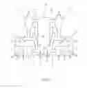
A cross sectional view of a fluidized bed heat exchanger
A top view on the FBHE 24 of FIG. 2 along line 3-3
A three dimensional view of the arrangement of heat transfer means and baffles in an FBHE
A three dimensional view of a coupling between a baffle extension and adjacent heat transfer tubes of heat transfer means
In the Figures identical and similar acting construction parts are identified by same numerals.
FIG. 1 discloses the general concept of a fluidized bed apparatus and its main components according to the present invention.
It comprises:
-
- A circulating fluidized bed reactor (CFBR) 10. Its lower part comprises a grate-like structure 12 through which air (arrow A1) is blown into a reactor chamber 14 via (not shown) nozzles, thus providing a fluidized bed (denseboard—DB—) above said grate 12, wherein said denseboard comprises a particulate material like coal, wood etc. to be burnt.
- The CFBR has two outlet ports 16 at opposite sides of its upper part, allowing a mixture of gas and solid particles exhausted from the CFBR to flow into associated separators 18, namely cyclone separators. The separators serve to separate solid particles from the gas.
- Transfer means 20, designed as ducts, extend from the lower end of each separator 18 downwardly and into an inlet port 22 along the ceiling 24c of a fluidized bed heat exchanger (FBHE) 24.
- A syphon-like tube construction 26 (U-shaped) extends from the lower end of each separator 18 into reactor chamber 14 and enters into chamber 14 shortly above grate 12 of said CFBR.
- The FBHE is equipped with (plate-like) heat transfer means 28 and an outlet port 30 merging into reactor chamber 14 at the same vertical height as tube construction 26.
This concept belongs to prior art. Insofar details are not further illustrated as known to the skilled person.
The invention includes one or more of the following features:
According to FIG. 2 the fluidized bed heat exchanger 24 displays an inlet port 22 at its upper end (in FIG. 2: top left) and an outlet port 30 at its upper end (in FIG. 2: top right), i. e. opposite to each other. Said outlet port 30 provides return means for solid particles which are further transported along a transfer duct into chamber 14. A common wall 14w of chamber 14 and FBHE 24 is also displayed.
Outlet port 30 comprises multiple flow through openings, arranged in a horizontal row with a distance to each other along a corresponding wall section of said wall 14w.
Said wall 14w is water-cooled, namely constructed of vertically extending tubes with fins running between adjacent tubes. The tubes are cooled by water fed through said tubes.
The through holes having the function of discrete outlet ports are shown in FIG. 2 in a slightly inclined orientation, with a lower end towards the fluidized bed heat exchanger 24 and a higher end towards the fluidized bed reactor chamber 14.
This inclined orientation (sloped outlet port 30) can be provided as part of a 3-dimensional profile (for example as a convexity 14w′) of said wall 14w towards the inner space/chamber of the fluidized bed heat exchanger 24 as shown in dotted lines in FIG. 2 and characterized by numeral 30′.
FIGS. 2 to 4 display the design and construction of a type of heat transfer means 28 within the fluidized bed heat exchanger 24. In FIG. 2 only one of said heat transfer means is shown. Further heat transfer means of equal design are placed at a distance to each other within FBHE 24 (perpendicular to the plane of projection), as schematically shown in FIG. 4.
Steam is fed into said means 28 via a central feeding line 42, then flowing through the meandering tube (as shown), representing said means 28, and escaping via a common outlet line 44, allowing to take heat from the particulate material (symbolized by dots P) moving through FBHE 24 between inlet port 22 and outlet port 30.
It is important that each of said means 28 is designed in a wall-like pattern and extending substantially parallel to the main flow direction of the solid particles on their way to and through the outlet port 30, symbolized in FIG. 2 by arrow S.
All tubes 28 are connected to the same feeding line 42 and outlet line 44.
The meandering tubes not only give the heat transfer means 28 a wall-like pattern but as well a grate-like structure to allow the particulate material to pass through as well in another horizontal direction, although to much less extent.
The horizontally extending sections of said tubes are about ten times longer than the vertically extending sections (FIG. 2 is not drawn to scale). Adjacent horizontal sections extent to a distance to each other being about the tube diameter.
As shown in FIGS. 2,4 the heat transfer means 28 extent about more than 60% of the chamber height, being the distance between a chamber bottom 24b and a chamber sealing 24c. In the embodiment each of said wall-like heat transfer means 28 extends from slightly above bottom 24b (or more precisely: from slightly above air nozzles 46, arranged in said bottom 24b, see FIG. 2) to slightly below inlet port 22 and from slightly off wall 14w to slightly off opposite wall 24w.
In prior art devices a separate entrance chamber with a discrete partition wall is constructed between wall 24w and an adjacent part of heat transfer means 28 as well as a separate return chamber between wall 14w and parts 28. These walls and chambers caused the stream of solid particles to flow up and down which is now avoided with the new design without any partition walls, which make the construction simpler, cheaper and more effective.
The particulate material may take a direct way from the inlet port 22 to the outlet port 30 (see arrow S) along the channels/gaps C formed between adjacent tubes (heat transfer means), as may be seen in FIG. 3.
Fluidization of the particulate material within FBHE 24 is achieved by said air nozzles 46 in the bottom area 24b. The particulate material is circulated by said purging means within FBHE 24 in order to optimize heat transfer from the hot solid particles P into the steam flowing within tube like heat transfer means 28 at a temperature of typically 300-625° C. and a pressure of between 80 and 300 bar.
Back to FIG. 2: The embodiment displayed further includes two baffles 50, 52, which extent from ceiling 24c downwardly, ending shortly above heat transfer means 28. These baffles 50, 52 extend substantially perpendicular to a straight line between inlet port 22 and outlet port 30 (dotted line L), i.e. perpendicular to the wall like heat transfer means 28.
Both baffles 50, 52 extend between opposite walls of FBHE 24 (only one, namely 24s is shown), being the walls bridging said walls 14w, 24w. The baffles 50, 52 are arranged at a distance to each other.
Each of said baffles 50, 52 comprise one opening O (see FIG. 4) to allow pressure adjustment (equalization) within the inner space of FBHE 24.
The said baffle(s) 50, 52 are further designed like a curtain, made of pipes, through which water of 270-374° C. at 90-320 bar is fed.
The baffles 50,52 urge the particulate material, flowing into chamber 10 via inlet port 22, to move downwardly (see arrow S) at baffle 50 and then to flow through said channels C (FIGS. 3,4) between adjacent heat transfer means 28 on their way between inlet port 22 and outlet port 30.
FIG. 4 shown the meandering wall like structure of heat transfer means (tubes) 28, again only schematically for better illustration. In view of the size of an industrial FBHE and the amount of solid material passing there through the skilled person will design the exact number, size and arrangement of heat transfer means 28, baffles 50,52, air nozzles 46 etc. in accordance with the specific demand.
FIG. 4,5 further display pipe-like extensions E, extending from the respective baffle 50,52 downwardly and into the spaces C between adjacent heat transfer means 28. The extensions E are in fluid communication with a central feeding line CFL to which pressure pipes PP are connected, which define the corresponding baffle 50,52. Each baffle 50,52 is made of one or more of such pressure pipes PP, arranged similarly as the heat exchange tubes ET of heat transfer means 28 to allow water of 270-400° C. and 90-320 bar pressure passing there through.
These extension pipes E are equipped with couplings B, shaped as brackets, as may be seen from FIG. 5. Each bracket/coupling B has a beam-like design with 3 openings through which 2 corresponding tube sections of a heat exchange tube ET and one section of a corresponding pipe extension E extend. For fitting, the said brackets B are made of steel half shelves, laid around the corresponding pipe/tube and then closed by a screw, bolt, clamp or the like.
It may be seen from FIG. 5 that the diameter of each pipe extension E is about 20% of the distance (width of channel C) between adjacent all like heat transfer means 28.
At the same time these extensions E and brackets B allow the mechanically integral and crosswise arrangement of heat transfer means 28 and baffles 50,52 within chamber 24.
Claims
1. Fluidized bed heat exchanger with a chamber (24), comprising
1.1 at least one solid particles inlet port (22)
1.2 at least one solid particles outlet port (30), arranged at a distance to the at least one inlet port (22),
1.3 means (46) for introducing a fluidizing gas from a bottom area (24b) of said chamber (24) into said chamber (24),
1.4 wall-like heat transfer means (28) in its lower part, extending
1.4.1 in a main flow direction of the solid particles on their way from the inlet port (22) to the outlet port (30),
1.4.2 substantially parallel to each other,
1.4.3 with a space (C) between adjacent heat transfer means (28),
1.5 at least one baffle (50,52) in its upper part, extending
1.5.1 substantially perpendicular to the heat transfer means (28),
1.5.2 downwardly from a chamber ceiling (24c),
1.5.3 with its lower end at a distance to the heat transfer means (28) and comprising
1.5.4 extensions (E), protruding into the space (C) between adjacent heat transfer means (28), and
1.6 couplings (B) to mechanically connect the said heat transfer means (28) to said extensions (E).
2. Fluidized bed heat exchanger according to claim 1, wherein the at least one baffle (50, 52) has at least one opening (O) to allow pressure adjusting.
3. Fluidized bed heat exchanger according to claim 1, wherein the at least one baffle (50, 52) is designed as a curtain with numerous small, discrete openings.
4. Fluidized bed heat exchanger according to claim 1, wherein the at least one baffle (50, 52) extends between opposite walls (24s) of the chamber (24).
5. Fluidized bed heat exchanger according to claim 1, wherein the at least one baffle (50, 52) is made of pressure pipes (PP) to transport water of 270° C. to 400° C. at 90 bar to 320 bar.
6. Fluidized bed heat exchanger according to claim 1, wherein the pressure pipes (PP) of each baffle (50, 52) are connected to a central feeding line (CFL).
7. Fluidized bed heat exchanger according to claim 1, with multiple baffles (50, 52), arranged parallel to each other at different distances to the inlet port (22).
8. Fluidized bed heat exchanger according to claim 1, wherein the heat transfer means (28) are designed as heat exchange tubes (ET) for conveying a heat transfer medium and arranged in a meandering fashion, thereby providing a vertically oriented wall-like pattern.
9. Fluidized bed heat exchanger according to claim 1, wherein the heat transfer means (28) are designed as heat exchange tubes (ET) to transport steam of 300° C. to 650° C. at 80 bar to 300 bar.
10. Fluidized bed heat exchanger according to claim 1, wherein the heat transfer means (28) are designed as heat exchange tubes (ET) which are connected to a central feeding tube (42, 44).
11. Fluidized bed heat exchanger according to claim 1, wherein the heat transfer means (28) and the baffles (50, 52), including their extensions (E), form a three-dimensional grid-like structure.
12. Fluidized bed heat exchanger according to claim 1, wherein the heat transfer means (28) and the baffles (50, 52) are arranged at about 90 degrees to each other.
13. Fluidized bed heat exchanger according to claim 1 with chamber walls (14w, 24w, 24s) being at least partially water-cooled.
14. Fluidized bed heat exchanger according to claim 13 with said chamber walls (14w, 24w, 24s) are made of pressure tubes, with fins between adjacent pressure tubes.
Images & Drawings included:


Sources:
- United States Patent and Trademark Office - verify current appl. status at the USPTO↗
Similar patent applications:
- » 20090293818
Fluidized bed heat exchanger for a circulating fluidized bed boiler and a circulating fluidized bed boiler with a fluidized bed heat exchanger - » 20150267968
FLUIDIZED BED HEAT EXCHANGER - » 20170016616
Fluidized bed heat exchanger - » 20230296326
Fluidized bed heat exchanger and method - » 20220018603
Fluidized-bed heat exchanger for conversion of thermal energy to electricity - » 20140053792
Fluidized bed heat exchange apparatus for recovering heat of flue gas for producing high temperature water - » 20140150735
BOILER HAVING A FLUIDIZED BED HEAT EXCHANGER - » 20090151902
Moving bed heat exchanger for circulating fluidized bed boiler - » 20240003534
A METHOD FOR HEATING A HEAT EXCHANGE MEDIUM IN A FLUIDIZED BED BOILER, A FLUIDIZED BED BOILER, AND A LOOPSEAL HEAT EXCHANGER - » 20160377351
HEAT EXCHANGE APPARATUS FOR CIRCULATING FLUIDIZED BED BOILERS
Recent applications in this class:
- » 20240093865 2024-03-21
Bubbling Fluidized Bed Reactor - » 20230400179 2023-12-14
CIRCULATING FLUIDIZED BED BOILER - » 20230392784 2023-12-07
DEVICE AND METHOD FOR SORTING A PARTICULATE STREAM - » 20210356120 2021-11-18
Device and method for chemical looping combustion, having a particle separator provided with an inclined intake duct - » 20200141570 2020-05-07
Recovery of chemicals from fuel streams - » 20190249866 2019-08-15
Circulating fluidized bed boiler with a loopseal heat exchanger - » 20190170346 2019-06-06
Raw material composition for preparing oxygen carrier particles, oxygen carrier particles prepared by using same, and method for preparing oxygen carrier particles - » 20190170345 2019-06-06
Circulating fluidized bed apparatus - » 20180187884 2018-07-05
Circulating fluidized bed boiler and a method of assembling a circulating fluidized bed boiler - » 20180180281 2018-06-28
Method for operating a fluidized bed boiler
Recent applications for this Assignee:
- » 20230158465 2023-05-25
FLUIDIZED BED REACTOR AND METHOD FOR OPERATING THE FLUIDIZED BED REACTOR - » 20210245094 2021-08-12
REACTOR FOR CLEANING FLUE GAS BY A DRY OR QUASI-DRY SORPTION PROCESS - » 20190358560 2019-11-28
Scrubber tray and a wet scrubber tower comprising such scrubber tray - » 20190170345 2019-06-06
Circulating fluidized bed apparatus - » 20180306434 2018-10-25
Circulating fluidized bed apparatus - » 20170348632 2017-12-07
SCRUBBER TOWER OF A FLUE GAS PURIFICATION DEVICE - » 20170016616 2017-01-19
Fluidized bed heat exchanger - » 20160290632 2016-10-06
Fluidized Bed Apparatus - » 20160281977 2016-09-29
Air distribution nozzle and a fluidized bed reactor - » 20160199776 2016-07-14
Scrubber tower of a flue gas purification device