Elevated Grip Safety for Accident Avoidance and Regulatory Compliance
US20170299302A1
2017-10-19
15/489,356
2017-04-17
Abstract:
A firearm has a frame with a trigger guard connected to the frame and defining a trigger space. The trigger guard has an upper limit, a trigger extending from the frame into the trigger space, and a grip connected to the frame adjacent the trigger guard. The grip has a back surface adapted for engagement by a gripping hand and a safety actuator adjacent to the back surface. The safety actuator is movable between a compressed position in which firearm operation is enabled, and a released position in which firearm operation is disabled. The safety actuator is at a level above the upper limit of the trigger guard.
Inventors:
- Matthew Andrei 1 🇺🇸 Hemet, CA, United States
- Shawndra Andrei 1 🇺🇸 Hemet, CA, United States
Assignee:
- Reidan Manufacturing, LLC 1 🇺🇸 Hemet, CA, United States
Interested in similar patents?
Get notified when new applications in this technology area are published.
Classification:
F41A17/22 » CPC main
Safety arrangements, e.g. safeties; Grip or stock safeties, i.e. safeties disengaged by clasping the grip or stock acting on the trigger
Description
CROSS-REFERENCE TO RELATED APPLICATION
This application claims the benefit of U.S. Provisional Patent Application No. 62/323,833 filed on Apr. 18, 2016, entitled “Elevated Grip Safety for Accident Avoidance and Regulatory Compliance,” which is hereby incorporated by reference in its entirety for all that is taught and disclosed therein.
BACKGROUND AND SUMMARY
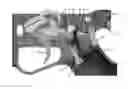
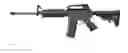
The State of California regulates the sale, manufacturing, and possession of “Assault Weapons” as defined in Penal Code Section 30515. Per Penal Code 30515(a) and CCR 11 §5469, “pistol grip that protrudes conspicuously beneath the action of the weapon” means a grip that allows for a pistol style grasp in which the web of the trigger hand (between the thumb and index finger) can be placed below the top of the exposed portion of the trigger while firing. Examples of rifles configured as “Assault Weapons” are shown in FIG. 1. These rifles can be fired with the web of the trigger hand below the line indicating the top of the exposed portion of the trigger. Examples of rifles NOT configured as “Assault Weapons” are shown in FIG. 2. These rifles cannot be fired with the web of the trigger hand below the line indicating the top of the exposed portion of the trigger
In order to comply with State regulations, a modified lower receiver with an elevated grip safety has been designed to provide safe, ergonomic firearm handling in a configuration that is desirable to many people for Self Defense, Hunting, and Sporting. This safety is also utilized to add an additional level of protection against negligent or accidental discharge of the weapon should the traditional manual safety become accidentally disengaged. This is a condition that can easily occur due to the large protrusion from the side of the receiver with the traditional manual safety. The protruding traditional manual safety easily catches on equipment and clothing while the rifle is being handled and the elevated grip safety design ensures that the rifle cannot fire until the trigger hand is in the proper firing position.
BRIEF DESCRIPTION OF THE DRAWINGS
FIG. 1 is a side view of the invention according to a preferred embodiment of the invention, as incorporated on a firearm.
FIG. 2 is a side view of the invention according to a preferred embodiment of the invention, as incorporated on a firearm.
FIG. 3 is a side view of a preferred embodiment of the invention, as incorporated on a firearm.
FIG. 4 is a left side isometric view of a preferred embodiment of the invention.
FIG. 5 is a left side schematic view of a preferred embodiment of the invention.
FIG. 6 is a left side schematic view of a preferred embodiment of the invention.
FIG. 7 is a left side isometric view of a preferred embodiment of the invention.
FIG. 8 is a left side isometric view of a preferred embodiment of the invention.
FIG. 9 is a left side internal isometric view of a preferred embodiment of the invention.
FIG. 10 is a left side internal isometric view of a preferred embodiment of the invention.
FIG. 11 is a left side internal isometric view of a preferred embodiment of the invention.
FIG. 12 is a left side internal isometric view of a preferred embodiment of the invention.
FIG. 13 is a left side internal isometric view of a preferred embodiment of the invention.
FIG. 14 is a left side internal isometric view of a preferred embodiment of the invention.
FIG. 15 is a left side internal isometric view of a preferred embodiment of the invention.
FIG. 16 is a left side internal isometric view of a preferred embodiment of the invention.
FIG. 17 is a left side internal isometric view of a preferred embodiment of the invention.
FIG. 18 is a left side internal isometric view of a preferred embodiment of the invention.
FIG. 19 is a left side internal isometric view of a preferred embodiment of the invention.
FIG. 20 is a left side internal isometric view of a preferred embodiment of the invention.
FIG. 21 is a left side internal isometric view of a preferred embodiment of the invention.
DETAILED DESCRIPTION OF THE PREFERRED EMBODIMENT
FIGS. 1, 2, and 3 show assembled rifles in multiple configurations and calibers. These configurations are similar in appearance to other rifles commonly referred to as AR15's or AR10's but with the distinct difference of the unique Lower Receiver with Elevated Grip Safety as described below.
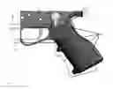
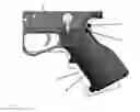
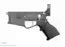
FIG. 4 shows the primary product being described, separated from the rest of the assembled rifle.
FIG. 5, the significant visible characteristics are as follows:
-
- 1) FIG. 5 item 1 is the traditional location of an AR15 or AR10 trigger guard. This new product includes a low profile trigger guard that has been lowered at dimension A in order to comply with State regulations.
- 2) The profile of a traditional grip is shown in FIG. 5 along the path indicated as feature 2. This new path has been rotated for regulatory compliance and improved ergonomics. In addition, the lower trigger guard has been raised at dimension B. Another key element of this design is the removal of material at the back strap of the handle as indicated by dimension C. This change permits the addition of the elevated grip safety while providing adequate space for the web of the trigger hand to comfortably grasp the handle.
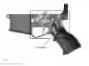
FIG. 6 details the rotation of the front strap of the handle about the center of the trigger pin hole 1 from the traditional profile at line 5 to the improved position at line 4. The position of the web of the trigger hand has also been rotated from its traditional position 3, about hole 1, to the regulatory compliant position 2.
FIG. 7, the Elevated Grip Safety rests completely above the top of the exposed portion of the trigger in an ergonomic position and will ensure the weapon cannot be accidentally discharged without the trigger hand in its intended position.
FIG. 8 shows a cross-section view through the center of the firearm. The following images are magnified views as indicated by Detail A.
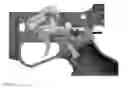
FIG. 9 lists the components involved with this design.
-
- 1) Elevated Grip Safety Lever (grip safety)—This lever is activated by the web of the trigger hand (between the thumb and index finger). It is a curved to rectangular shape of rigid, corrosion resistant, material (Anodized aluminum, plated or black oxide steel, plastic, Etc.). This lever pushes or cams against the safety catch link 2 as it rotates or slides within the lower receiver 12 from its rearward, safe position, to its forward fire position. Some possible alternative shapes and directions of travel can be seen in FIG. 19 item 1, and FIG. 24.
- 2) Safety Catch Link—This ridged, corrosion resistant cylindrical pin (Anodized aluminum, plated or black oxide steel, plastic, Etc.) is pushed by the Grip safety lever 1 when traveling from the “safe” to “fire” position. This in turn pushes upon the safety catch 9.
- 3) Handle Mounting Screw—This screw mounts the handle 4 to the lower receiver 12.
- 4) Handle—This is the ridged, corrosion resistant handle with unique geometry previously described that facilitates the unique grip position and elevated grip safety of this firearm. This handle can be machined, cast, molded, printed from any ridged, corrosion resistant, lightweight material such as plastic, Aluminum, Etc.
- 5) Trigger—This can be a standard “mil-spec” trigger or many aftermarket drop-in triggers produced by a variety of manufacturers or a custom made, extended length trigger made from any ridged, corrosion resistant material (Anodized aluminum, plated or black oxide steel, plastic, Etc.).
- 6) Hammer—This can be a standard “mil-spec” hammer or a part of many aftermarket drop-in trigger groups produced by a variety of manufacturers made from any ridged, corrosion resistant material that withstands the impact against the firing pin (Anodized aluminum, plated or black oxide steel, Etc.).
- 7) Disconnector—This can be a standard “mil-spec” disconnector or part of many aftermarket drop-in trigger groups produced by a variety of manufacturers made from any ridged, corrosion resistant material that withstands the force and wear of engaging the hammer 6 (Anodized aluminum, plated or black oxide steel, Etc.).
- 8) Manual Safety—This can be a standard “mil-spec” safety or one of many aftermarket drop-in safeties produced by a variety of manufacturers. It can be made from any ridged, corrosion resistant material that withstands the wear of rotating with the lower receiver 12 (Anodized aluminum, plated or black oxide steel, Etc.).
- 9) Safety Catch—This rigid, corrosion resistant trigger block or safety catch is rotated by force of contact with the safety catch link 2 against the force of the Safety Catch Detent Spring 11 through the Safety Catch Detent 10. This catch blocks the travel of the trigger unless the grip safety lever 1 is pressed by the web of the trigger hand.
- 10) Safety Catch Detent—This can be a standard, repurposed, “mil-spec” bolt catch detent or similarly purposed detent produced by a variety of manufacturers. It can be made from any ridged, corrosion resistant material (Anodized aluminum, plated or black oxide steel, Etc.) that withstands the wear of sliding within the lower receiver 12 and safety catch 9.
- 11) Safety Catch Detent Spring—This is a multi-purpose compression spring that, on one end, pushes upon the grip safety lever 1 to assist in returning the lever to its rearward “safe” position. On the opposite end, the spring pushes upon the safety catch detent 10 and safety catch 9 to ensure the trigger is blocked unless the grip safety lever 1 is pressed by the web of the trigger hand.
- 12) Lower Receiver—This receiver is the serialized “firearm” component of the rifle made of a cast, molded, forged, or machined corrosion resistant material (steel, Aluminum, Titanium, plastic, Etc.). This receiver houses all of the other components listed.
- 13) Grip Safety Lever Retaining Screw/Upper Receiver Tensioning Screw—This screw retains the grip safety lever 1 within the lower receiver 12 while simultaneously creating tension against the upper receiver to eliminate any excessive movement between the upper and lower receivers.
FIG. 9 shows the firearm in the “at rest”, safe condition with the manual safety 8 and grip safety lever 1 both in the safe positions.
FIG. 10 shows the manual safety 8 rotated to the fire position. This rotation makes space the safety catch 9 to block the upward travel of the trigger 5 at position A by force of the Safety Catch Detent Spring 11 through the Safety Catch Detent 10.
FIG. 11 has the grip safety 1 depressed and rotating about point A, pushing upon the safety catch link 2, causing the safety catch 9 to rotate clockwise about point B against the Safety Catch Detent 10 and Safety Catch Detent Spring 11 force until the safety catch 9 is out of the range of motion of the trigger. At this point, the manual safety 8 and grip safety 1 have both been forced into the “fire” positions in either order.
FIG. 12, with both safeties in the fire position, the trigger 5 can be pressed rearward. This causes the trigger 5 to rotate counter-clockwise about point A until the hammer sear is released at point B.
FIG. 13, the hammer 6 rotates counter-clockwise under spring pressure until obstructed.
FIG. 14, upon the next cycling of the firearm, the hammer 6 rotates clockwise until it is caught by disconnector 7 at point A.
FIG. 15, when the trigger 5 is released, it rotates clockwise about point C under spring force to its original position until the hammer 6 is released from the disconnector 7 and the sear is reset at point D. If at any point the grip safety 1 is released, the safety catch detent spring 11 will push the safety catch detent 10 against the safety catch 9, causing safety catch 9 to rotate counter-clockwise about point B and re-obstruct the upward travel of the trigger 5. Simultaneously, safety catch 9 will push against safety catch link 2 and push the grip safety 1 to its rearward safe position about point A.
FIG. 16, an alternative design is shown using a multi piece safety catch link system with items 2 and 4 pushed to the safe position by spring 3. The trigger 5 travel is obstructed by safety catch 6 at point A.
FIG. 17, continuing from FIG. 16, when grip safety 1 depressed and rotates about point A, pushing upon the safety catch link 2 and 4, causing the safety catch 6 to move rearward against spring force until the safety catch 6 is out of the range of motion of the trigger at point C.
FIG. 18, this is yet another possible configuration that could be used individually or in conjunction with other designs. This configuration blocks the downward travel of the front of trigger 5 at point A.
FIG. 19, when grip safety 1 is depressed and rotates about point A, the safety catch link 2 is pushed forward until it no longer obstructs the downward travel of the front of trigger 5 at point B.
FIGS. 20 and 21, a push button style grip safety is used in place of a lever style grip safety. The resulting action is the same as described above.
Claims
We claim:1. A firearm comprising:
a frame;
a trigger guard connected to the frame and defining a trigger space;
the trigger guard having an upper limit;
a trigger extending from the frame into the trigger space;
a grip connected to the frame adjacent the trigger guard;
the grip having a back surface adapted for engagement by a gripping hand;
a safety actuator adjacent to the back surface and movable between a compressed position in which firearm operation is enabled, and a released position in which firearm operation is disabled; and
the safety actuator being at a level above the upper limit of the trigger guard.
Images & Drawings included:


Sources:
- United States Patent and Trademark Office - verify current appl. status at the USPTO↗
Recent applications in this class:
- » 20220120525 2022-04-21
Grip safety interlock for firearm - » 20180112941 2018-04-26
Safety actuator for AK-47 firearms - » 20160202009 2016-07-14
Secondary safety - » 20160076842 2016-03-17
Firearm grip safety - » 20150292827 2015-10-15
Safety device for a portable long-barrelled firearm or pneumatic weapon - » 20110107638 2011-05-12
Hand gun - » 20090158634 2009-06-25
HANDGUN - » 20080222935 2008-09-18
Three-Piece Grip Safety