Apparatus and method for providing optimal gear advice
US20170314679A1
2017-11-02
15/528,767
2015-11-26
✅ Patent granted
US 10,436,602 B2
2019-10-08
WO; PCT/EP2015/077830; 20151126
WO; WO2016/083535; 20160602
David J Hlavka
2035-11-26
Abstract:
A method and apparatus for providing an indication to a driver of a geared vehicle that the vehicle is not in an optimal gear is disclosed. The method comprises determining a current gear of the vehicle and determining a current speed of a drive unit of the vehicle. An indication is then provided to the driver of the vehicle that the vehicle is not in an optimal gear when: (i) the determined current speed of the drive unit is greater than a predetermined threshold; and (ii) the determined current gear of the vehicle is less than a maximum gear of the vehicle. A method and apparatus is also disclosed for determining a score indicative of the amount of time during a journey on a road network that a geared vehicle is driven in an optimal gear.
Inventors:
- Alexander Schmidt 7 🇩🇪 Halle, Germany
- Paul Roeland Verheijen 9 🇳🇱 Heemstede, Netherlands
- Jasper Johannes Anthonius Pauwelussen 6 🇳🇱 Den Haag, Netherlands
- Marco Leupold 5 🇩🇪 Leipzig, Germany
- Christoph Ebert 5 🇩🇪 Leipzig, Germany
- Steffen Orlowsky 6 🇩🇪 Dessau-Rosslau, Germany
- Lars Dietzel 1 🇩🇪 Schkopau, Germany
- Jasper Johannes Anthonius Pauwelussen 5 🇳🇱 The Hague, Netherlands
Assignee:
- TomTom Telematics B.V. 13 🇳🇱 Amsterdam, Netherlands
Applicant:
Interested in similar patents?
Get notified when new applications in this technology area are published.
Classification:
G01C21/3697 » CPC main
Navigation; Navigational instruments not provided for in groups - specially adapted for navigation in a road network; Route searching; Route guidance; Input/output arrangements for on-board computers Output of additional, non-guidance related information, e.g. low fuel level
F16H63/42 » CPC main
Control outputs to change-speed- or reversing-gearings for conveying rotary motion comprising signals other than signals for actuating the final output mechanisms Ratio indicator devices
F16H59/70 » CPC further
Control inputs to control units of change-speed-, or reversing-gearings for conveying rotary motion; Inputs being a function of gearing status dependent on the ratio established
G07C5/085 » CPC further
Registering or indicating the working of vehicles; Registering or indicating performance data other than driving, working, idle, or waiting time, with or without registering driving, working, idle or waiting time; Registering performance data using electronic data carriers
F16H2059/366 » CPC further
Control inputs to control units of change-speed-, or reversing-gearings for conveying rotary motion; Inputs being a function of speed Engine or motor speed
B60Y2300/52 » CPC further
Purposes or special features of road vehicle drive control systems Engine fuel consumption
F16H59/36 IPC
Control inputs to control units of change-speed-, or reversing-gearings for conveying rotary motion Inputs being a function of speed
F16H2063/426 » CPC further
Control outputs to change-speed- or reversing-gearings for conveying rotary motion comprising signals other than signals for actuating the final output mechanisms; Ratio indicator devices with means for advising the driver for proper shift action, e.g. prompting the driver with allowable selection range of ratios
G01C21/36 IPC
Navigation; Navigational instruments not provided for in groups - specially adapted for navigation in a road network; Route searching; Route guidance Input/output arrangements for on-board computers
G07C5/08 IPC
Registering or indicating the working of vehicles Registering or indicating performance data other than driving, working, idle, or waiting time, with or without registering driving, working, idle or waiting time
F16H59/44 » CPC further
Control inputs to control units of change-speed-, or reversing-gearings for conveying rotary motion; Inputs being a function of speed dependent on machine speed of the machine, e.g. the vehicle
F16H59/46 » CPC further
Control inputs to control units of change-speed-, or reversing-gearings for conveying rotary motion; Inputs being a function of speed dependent on a comparison between speeds
B60W30/18 » CPC further
Purposes of road vehicle drive control systems not related to the control of a particular sub-unit, e.g. of systems using conjoint control of vehicle sub-units, or advanced driver assistance systems for ensuring comfort, stability and safety or drive control systems for propelling or retarding the vehicle Propelling the vehicle
B60R16/0236 » CPC further
Electric or fluid circuits specially adapted for vehicles and not otherwise provided for; Arrangement of elements of electric or fluid circuits specially adapted for vehicles and not otherwise provided for electric constitutive elements for transmission of signals between vehicle parts or subsystems; Circuits relating to the driving or the functioning of the vehicle for economical driving
F16H61/0213 » CPC further
Control functions within change-speed- or reversing-gearings for conveying rotary motion characterised by the signals used the signals being electric for gearshift control, e.g. control functions for performing shifting or generation of shift signal characterised by the method for generating shift signals
B60W50/14 » CPC further
Details of control systems for road vehicle drive control not related to the control of a particular sub-unit, e.g. process diagnostic or vehicle driver interfaces; Interaction between the driver and the control system Means for informing the driver, warning the driver or prompting a driver intervention
B60W30/18072 » CPC further
Purposes of road vehicle drive control systems not related to the control of a particular sub-unit, e.g. of systems using conjoint control of vehicle sub-units, or advanced driver assistance systems for ensuring comfort, stability and safety or drive control systems for propelling or retarding the vehicle; Propelling the vehicle related to particular drive situations Coasting
G07C5/0816 » CPC further
Registering or indicating the working of vehicles; Registering or indicating performance data other than driving, working, idle, or waiting time, with or without registering driving, working, idle or waiting time Indicating performance data, e.g. occurrence of a malfunction
G08G1/09626 » CPC further
Traffic control systems for road vehicles; Arrangements for giving variable traffic instructions having an indicator mounted inside the vehicle, e.g. giving voice messages where the origin of the information is within the own vehicle, e.g. a local storage device, digital map
G08G1/052 » CPC further
Traffic control systems for road vehicles; Detecting movement of traffic to be counted or controlled with provision for determining speed or overspeed
G07C5/02 » CPC further
Registering or indicating the working of vehicles Registering or indicating driving, working, idle, or waiting time only
B60W30/18109 » CPC further
Purposes of road vehicle drive control systems not related to the control of a particular sub-unit, e.g. of systems using conjoint control of vehicle sub-units, or advanced driver assistance systems for ensuring comfort, stability and safety or drive control systems for propelling or retarding the vehicle; Propelling the vehicle related to particular drive situations Braking
B60W30/18136 » CPC further
Purposes of road vehicle drive control systems not related to the control of a particular sub-unit, e.g. of systems using conjoint control of vehicle sub-units, or advanced driver assistance systems for ensuring comfort, stability and safety or drive control systems for propelling or retarding the vehicle; Propelling the vehicle related to particular drive situations; Braking Engine braking
B60K31/00 » CPC further
Vehicle fittings, acting on a single sub-unit only, for automatically controlling vehicle speed, i.e. preventing speed from exceeding an arbitrarily established velocity or maintaining speed at a particular velocity, as selected by the vehicle operator
G01P1/06 » CPC further
Details of instruments Indicating or recording devices, e.g. for remote indication
G07C5/004 » CPC further
Registering or indicating the working of vehicles Indicating the operating range of the engine
G07C5/008 » CPC further
Registering or indicating the working of vehicles communicating information to a remotely located station
G07C5/06 » CPC further
Registering or indicating the working of vehicles; Registering or indicating driving, working, idle, or waiting time only in graphical form
G07C5/0825 » CPC further
Registering or indicating the working of vehicles; Registering or indicating performance data other than driving, working, idle, or waiting time, with or without registering driving, working, idle or waiting time; Indicating performance data, e.g. occurrence of a malfunction using optical means
G07C5/0841 » CPC further
Registering or indicating the working of vehicles; Registering or indicating performance data other than driving, working, idle, or waiting time, with or without registering driving, working, idle or waiting time Registering performance data
G08G1/0112 » CPC further
Traffic control systems for road vehicles; Detecting movement of traffic to be counted or controlled; Measuring and analyzing of parameters relative to traffic conditions based on the source of data from the vehicle, e.g. floating car data [FCD]
G08G1/0137 » CPC further
Traffic control systems for road vehicles; Detecting movement of traffic to be counted or controlled; Measuring and analyzing of parameters relative to traffic conditions for specific applications
G08G1/0141 » CPC further
Traffic control systems for road vehicles; Detecting movement of traffic to be counted or controlled; Measuring and analyzing of parameters relative to traffic conditions for specific applications for traffic information dissemination
G08G1/09685 » CPC further
Traffic control systems for road vehicles; Arrangements for giving variable traffic instructions having an indicator mounted inside the vehicle, e.g. giving voice messages; Systems involving transmission of navigation instructions to the vehicle where different aspects are considered when computing the route where the complete route is computed only once and not updated
G08G1/096716 » CPC further
Traffic control systems for road vehicles; Arrangements for giving variable traffic instructions having an indicator mounted inside the vehicle, e.g. giving voice messages; Systems involving transmission of highway information, e.g. weather, speed limits where the received information might be used to generate an automatic action on the vehicle control where the received information does not generate an automatic action on the vehicle control
G08G1/096741 » CPC further
Traffic control systems for road vehicles; Arrangements for giving variable traffic instructions having an indicator mounted inside the vehicle, e.g. giving voice messages; Systems involving transmission of highway information, e.g. weather, speed limits where a selection of the information might take place where the source of the transmitted information selects which information to transmit to each vehicle
G08G1/096775 » CPC further
Traffic control systems for road vehicles; Arrangements for giving variable traffic instructions having an indicator mounted inside the vehicle, e.g. giving voice messages; Systems involving transmission of highway information, e.g. weather, speed limits where the system is characterised by the origin of the information transmission where the origin of the information is a central station
G08G1/096861 » CPC further
Traffic control systems for road vehicles; Arrangements for giving variable traffic instructions having an indicator mounted inside the vehicle, e.g. giving voice messages; Systems involving transmission of navigation instructions to the vehicle where the output is provided in a suitable form to the driver where the immediate route instructions are output to the driver, e.g. arrow signs for next turn
B60K2370/172 » CPC further
Details of arrangements or adaptations of instruments specially adapted for vehicles, not covered by groups; Type of information Driving mode indication
B60K2370/174 » CPC further
Details of arrangements or adaptations of instruments specially adapted for vehicles, not covered by groups; Type of information Economic driving
B60W2030/1809 » CPC further
Purposes of road vehicle drive control systems not related to the control of a particular sub-unit, e.g. of systems using conjoint control of vehicle sub-units, or advanced driver assistance systems for ensuring comfort, stability and safety or drive control systems for propelling or retarding the vehicle; Propelling the vehicle related to particular drive situations; Coasting Without torque flow between driveshaft and engine, e.g. with clutch disengaged or transmission in neutral
B60W2510/0623 » CPC further
Input parameters relating to a particular sub-units; Combustion engines, Gas turbines; Position of fuel or air injector Fuel flow rate
B60W40/09 » CPC further
Estimation or calculation of driving parameters for road vehicle drive control systems not related to the control of a particular sub unit, related to drivers or passengers Driving style or behaviour
B60W2510/0642 » CPC further
Input parameters relating to a particular sub-units; Combustion engines, Gas turbines; Engine speed Idle condition
B60W2510/0647 » CPC further
Input parameters relating to a particular sub-units; Combustion engines, Gas turbines; Engine speed Coasting condition
B60W2520/10 » CPC further
Input parameters relating to overall vehicle dynamics Longitudinal speed
B60W2520/105 » CPC further
Input parameters relating to overall vehicle dynamics; Longitudinal speed Longitudinal acceleration
B60W2710/0655 » CPC further
Output or target parameters relating to a particular sub-units; Combustion engines, Gas turbines; Engine speed Coasting condition
F16H2061/0218 » CPC further
Control functions within change-speed- or reversing-gearings for conveying rotary motion characterised by the signals used the signals being electric for gearshift control, e.g. control functions for performing shifting or generation of shift signal characterised by the method for generating shift signals Calculation or estimation of the available ratio range, i.e. possible gear ratios, e.g. for prompting a driver with a display
G01C21/3632 » CPC further
Navigation; Navigational instruments not provided for in groups - specially adapted for navigation in a road network; Route searching; Route guidance; Input/output arrangements for on-board computers; Details of the output of route guidance instructions Guidance using simplified or iconic instructions, e.g. using arrows
G01C21/3673 » CPC further
Navigation; Navigational instruments not provided for in groups - specially adapted for navigation in a road network; Route searching; Route guidance; Input/output arrangements for on-board computers; Display of a road map Labelling using text of road map data items, e.g. road names, POI names
Y02T10/84 » CPC further
Road transport of goods or passengers; Technologies aiming to reduce greenhouse gasses emissions common to all road transportation technologies Data processing systems or methods, management, administration
Y02T10/84 » CPC further
Road transport of goods or passengers; Technologies aiming to reduce greenhouse gasses emissions common to all road transportation technologies Data processing systems or methods, management, administration
G01P1/00 IPC
Details of instruments
B60R16/023 IPC
Electric or fluid circuits specially adapted for vehicles and not otherwise provided for; Arrangement of elements of electric or fluid circuits specially adapted for vehicles and not otherwise provided for electric constitutive elements for transmission of signals between vehicle parts or subsystems
G07C5/00 IPC
Registering or indicating the working of vehicles
F16H61/02 IPC
Control functions within change-speed- or reversing-gearings for conveying rotary motion characterised by the signals used
G08G1/0962 IPC
Traffic control systems for road vehicles; Arrangements for giving variable traffic instructions having an indicator mounted inside the vehicle, e.g. giving voice messages
G08G1/0968 IPC
Traffic control systems for road vehicles; Arrangements for giving variable traffic instructions having an indicator mounted inside the vehicle, e.g. giving voice messages Systems involving transmission of navigation instructions to the vehicle
B60W50/00 IPC
Details of control systems for road vehicle drive control not related to the control of a particular sub-unit, e.g. process diagnostic or vehicle driver interfaces
G08G1/0129 » CPC further
Traffic control systems for road vehicles; Detecting movement of traffic to be counted or controlled; Measuring and analyzing of parameters relative to traffic conditions; Traffic data processing for creating historical data or processing based on historical data
B60W2030/18081 » CPC further
Purposes of road vehicle drive control systems not related to the control of a particular sub-unit, e.g. of systems using conjoint control of vehicle sub-units, or advanced driver assistance systems for ensuring comfort, stability and safety or drive control systems for propelling or retarding the vehicle; Propelling the vehicle related to particular drive situations; Coasting With torque flow from driveshaft to engine, i.e. engine being driven by vehicle
B60W2510/0638 » CPC further
Input parameters relating to a particular sub-units; Combustion engines, Gas turbines Engine speed
B60W2510/1005 » CPC further
Input parameters relating to a particular sub-units; Change speed gearings Transmission ratio engaged
G08G1/01 IPC
Traffic control systems for road vehicles Detecting movement of traffic to be counted or controlled
F16H61/0246 » CPC further
Control functions within change-speed- or reversing-gearings for conveying rotary motion characterised by the signals used the signals being electric for gearshift control, e.g. control functions for performing shifting or generation of shift signal characterised by initiating reverse gearshift
G08G1/0967 » CPC further
Traffic control systems for road vehicles; Arrangements for giving variable traffic instructions having an indicator mounted inside the vehicle, e.g. giving voice messages Systems involving transmission of highway information, e.g. weather, speed limits
G08G1/096827 » CPC further
Traffic control systems for road vehicles; Arrangements for giving variable traffic instructions having an indicator mounted inside the vehicle, e.g. giving voice messages; Systems involving transmission of navigation instructions to the vehicle where the transmitted instructions are used to compute a route where the route is computed onboard
Description
FIELD OF THE INVENTION
The present invention relates to a method and apparatus for evaluating vehicle driving, for example, for provision to a driver of the vehicle and/or to a manager of a fleet of vehicles. For example, the invention can in embodiments determine times at which a driver of a vehicle is not driving in an optimal gear, e.g. based on gear information for the vehicle determined from data collected via the OBD port of the vehicle, and that can lead to reductions in fuel efficiency if not rectified.
BACKGROUND OF THE INVENTION
Increasingly it is desired to improve a fuel economy of vehicles, particularly, although not exclusively, vehicles powered by fossil fuels, such as petrol and diesel. Although it will be realised that improving the fuel economy of any vehicle, including electric, hybrid and hydrogen powered vehicles, for example, is also desired. Some efforts at improving the fuel economy of vehicles are focussed on increasing an efficiency of the vehicle, such as a mechanical and/or electrical efficiency of the vehicle. It has also been realised that the manner in which a vehicle is driven can have a significant impact of the vehicle's economy.
Knowing the current gear and the maximum gear of a vehicle can be useful for various purposes. For example, having this information allows current gear information to be collected or driving behaviour to be monitored. This information also allows the development of methods and systems for monitoring the performance of drivers of vehicles over one or more journeys, and methods and systems for providing feedback to a driver in order to promote more economical driving.
SUMMARY OF THE INVENTION
In accordance with a first aspect of the present invention there is provided a method of providing an indication to a driver of a geared vehicle that the vehicle is not in an optimal gear, comprising:
determining a current gear of the vehicle;
determining a current speed of a drive unit of the vehicle; and
providing an indication to the driver of the vehicle that the vehicle is not in an optimal gear when: (i) the determined current speed of the drive unit is greater than a predetermined threshold; and (ii) the determined current gear of the vehicle is less than a maximum gear of the vehicle.
The present invention extends to an apparatus for carrying out a method in accordance with any of the aspects or embodiments of the invention herein described.
Thus, in accordance with another aspect of the invention there is provided an apparatus for providing an indication to a driver of a geared vehicle that the vehicle is not in an optimal gear, comprising:
means for determining a current gear of the vehicle;
means for determining a current speed of a drive unit of the vehicle; and
means for providing an indication to the driver of the vehicle that the vehicle is not in an optimal gear when: (i) the determined current speed of the drive unit is greater than a predetermined threshold; and (ii) the determined current gear of the vehicle is less than a maximum gear of the vehicle.
Similarly, in accordance with another aspect of the invention there is provided an apparatus for providing an indication to a driver of a geared vehicle that the vehicle is not in an optimal gear, comprising at least one processor and a memory containing instructions that, when executed by the at least one processor, cause the apparatus to:
determine a current gear of the vehicle;
determine a current speed of a drive unit of the vehicle; and
provide an indication to the driver of the vehicle that the vehicle is not in an optimal gear when: (i) the determined current speed of the drive unit is greater than a predetermined threshold; and (ii) the determined current gear of the vehicle is less than a maximum gear of the vehicle.
As will be appreciated by those skilled in the art, this further aspect of the present invention can and preferably does include any one or more or all of the preferred and optional features of the invention described herein in respect of any of the other aspects of the invention, as appropriate. If not explicitly stated, the system of the present invention herein may comprise means for carrying out any step described in relation to the method of the invention in any of its aspects or embodiments, and vice versa.
Therefore, and as will be appreciated, the present invention requires the determination, or suitable means for making such a determination, of when: (i) the determined current speed of the drive unit is greater than a predetermined threshold; and (ii) the determined current gear of the vehicle is less than a maximum gear of the vehicle.
In embodiments, the predetermined threshold is based on a fuel type used by the drive unit of the vehicle. The fuel type may be one of diesel or petrol. A first predetermined threshold may be used for a petrol drive unit, and a second predetermined threshold may be used for a diesel drive unit, wherein the first predetermined threshold is higher than the second predetermined threshold.
In embodiments, at least one of the current gear of the vehicle and the current speed of the drive unit is received from a remote device.
In embodiments, the determination of the current gear of the vehicle may comprise: receiving a speed-rpm ratio of the vehicle, based on a speed of the vehicle and a corresponding speed of the drive unit of the vehicle; evaluating a difference between the speed-rpm ratio and a speed-rpm ratio from an entry in a gear table, said gear table comprising a plurality of entries, each entry associating an available gear of the geared vehicle with a speed-rpm ratio; and determining that the current gear of the vehicle is the available gear of the entry in the gear table when the difference is within a predetermined threshold. The maximum gear of the vehicle may also be determined from the gear table.
In one example, the gear table may be generated by: receiving a plurality of speed-rpm ratios of the vehicle, each based on a speed of the vehicle and a corresponding speed of a drive unit of the vehicle; assigning each of the plurality of speed-rpm ratios to a relevant one of a plurality of speed-rpm ratio bins in a histogram; thresholding the histogram to identify a plurality of peaks, each peak having an associated speed-rpm ratio; and determining a plurality of available gears as the associated speed-rpm ratios of the plurality of peaks.
In another alternate example, the gear table may be generated by: receiving a plurality of successive speed-rpm ratios of the vehicle, each based on a speed of the vehicle and a corresponding speed of a drive unit of the vehicle; evaluating a consistency measure indicative of a variation in the plurality of successive speed-rpm ratios over time; and determining that the plurality of successive speed-rpm ratios correspond to an available gear when the consistency measure is less than a predetermined threshold. In this example, when the plurality of successive speed-rpm ratios are determined to correspond to an available gear, an entry may be added to the gear table for the available gear based on the plurality of successive speed-rpm ratios. Additionally or alternatively, when the plurality of successive speed-rpm ratios are determined to correspond to an available gear, an existing entry in the gear table for the available gear may be adjusted based on the plurality of successive speed-rpm ratios.
In either example, the method may further comprise: receiving a speed of the drive unit of the vehicle when the vehicle is standing still; storing the received speed of the drive unit as a no-load rpm; and subsequently ignoring at least one of the received speed-rpm ratios of the vehicle if the speed of the drive unit of the vehicle on which at least one speed-rpm ratio is based is within a predetermined threshold of the no-load rpm.
The determination of an available gear of the geared vehicle for use in generating the gear table can be additionally based on an indication of an acceleration state of the vehicle. The indication of the acceleration state of the vehicle can be given by an acceleration signal or a plurality of successive speed signals. The determination of an available gear of the geared vehicle for use in generating the gear table can additionally include a determination of a reverse gear based on an acceleration signal indicative of reverse acceleration following at least one speed signal indicative of the vehicle speed being zero.
In embodiments, the determination that the vehicle is not in an optimal gear can further include: determining a coasting state of the vehicle; and providing an indication to the driver of the vehicle that the vehicle is not in an optimal gear when: (i) the determined current speed of the drive unit is greater than a predetermined threshold; (ii) the determined current gear of the vehicle is less than a maximum gear of the vehicle; and (iii) the determined coasting state of the vehicle indicates the vehicle is not currently coasting.
The determination of the coasting state of the vehicle can be determined based upon at least one of the speed of the drive unit of the vehicle and a fuel usage rate of the drive unit of the vehicle. The coasting state of the vehicle can be determined to be one of: coasting in-gear, coasting in neutral and/or no coasting. The coasting state can be determined based upon a comparison between the fuel usage rate and at least one predetermined threshold fuel usage rate, which may be, or be based on, an idle fuel usage rate of the vehicle. The coasting state can be determined based upon a comparison between the speed of the drive unit and at least one predetermined threshold speed, which may be, or be based on, an idling speed of the drive unit, that is typically determined when the vehicle is stationary.
In embodiments, the provision of an indication to the driver that the vehicle is not in an optimal gear comprises at least one of: displaying a graphical icon on a display device within the vehicle; providing an audio warning to the driver; and providing an a haptic warning to the driver.
The present invention may, in embodiments, further comprise: determining a first time indicative of the total driving time of a journey on road network; determining a second time indicative of the driving time during the journey that the vehicle was not in an optimal gear; and determining a score indicative of the amount of time during the journey that the vehicle was driven in an optimal gear based on the first and second times.
It is believed that the determination of a score in this manner may be new and advantageous in its own right. Thus, in accordance with a further aspect of the invention there is provided a method of determining a score indicative of the amount of time during a journey on a road network that a geared vehicle is driven in an optimal gear, comprising:
determining a first time indicative of the total driving time of the journey;
determining a second time indicative of the driving time during the journey that the vehicle was not in an optimal gear, wherein the vehicle is not in an optimal gear when: (i) a current speed of the drive unit of the vehicle is greater than a predetermined threshold; and (ii) a current gear of the vehicle is less than a maximum gear of the vehicle; and
determining a score indicative of the amount of time during the journey that the vehicle was driven in an optimal gear based on the first and second times.
The present invention extends to an apparatus for carrying out a method in accordance with any of the aspects or embodiments of the invention herein described.
Thus, in accordance with another aspect of the invention there is provided an apparatus for determining a score indicative of the amount of time during a journey on a road network that a geared vehicle is driven in an optimal gear, comprising:
means for determining a first time indicative of the total driving time of the journey;
means for determining a second time indicative of the driving time during the journey that the vehicle was not in an optimal gear, wherein the vehicle is not in an optimal gear when: (i) a current speed of the drive unit of the vehicle is greater than a predetermined threshold; and (ii) a current gear of the vehicle is less than a maximum gear of the vehicle; and
means for determining a score indicative of the amount of time during the journey that the vehicle was driven in an optimal gear based on the first and second times.
Similarly, in accordance with another aspect of the invention there is provided an apparatus for determining a score indicative of the amount of time during a journey on a road network that a geared vehicle is driven in an optimal gear, comprising at least one processor and a memory containing instructions that, when executed by the at least one processor, cause the apparatus to:
determine a first time indicative of the total driving time of the journey;
determine a second time indicative of the driving time during the journey that the vehicle was not in an optimal gear, wherein the vehicle is not in an optimal gear when: (i) a current speed of the drive unit of the vehicle is greater than a predetermined threshold; and (ii) a current gear of the vehicle is less than a maximum gear of the vehicle; and
determine a score indicative of the amount of time during the journey that the vehicle was driven in an optimal gear based on the first and second times.
As will be appreciated by those skilled in the art, this further aspect of the present invention can and preferably does include any one or more or all of the preferred and optional features of the invention described herein in respect of any of the other aspects of the invention, as appropriate. If not explicitly stated, the system of the present invention herein may comprise means for carrying out any step described in relation to the method of the invention in any of its aspects or embodiments, and vice versa.
In embodiments, the determination of the score is based on a ratio of the second time to the first time. The invention may further comprise at least one of: displaying a representation of the score on a display device within the vehicle; and transmitting the determined score for display on a remote device.
The apparatus that performs the invention, in accordance with any of its aspects and embodiments, is a vehicle tracking device, a portable navigation device or a navigation device integrated into the vehicle. The apparatus may comprise a receiver, which may be a wireless receiver, to receive at least one of the current gear of the vehicle and the current speed of the drive unit from a remote device coupled to an on-board diagnostics (OBD) port of the vehicle.
Methods in accordance with the present invention may be implemented at least partially using software, e.g. computer programs. The present invention thus also extends to a computer program comprising computer readable instructions executable to perform a method according to any of the embodiments of the invention.
The invention thus also extends to a computer software carrier comprising software which when used to operate a system or apparatus comprising data processing means causes, in conjunction with said data processing means, said apparatus or system to carry out the steps of a method in accordance with embodiments of the present invention. Such a computer software carrier could be a non-transitory physical storage medium, such as a ROM chip, CD ROM or disk, or could be a signal, such as an electronic signal over wires, an optical signal or a radio signal such as to a satellite or the like.
The present invention in accordance with any of its further aspects or embodiments may include any of the features described in reference to other aspects or embodiments of the invention to the extent it is not mutually inconsistent therewith.
Advantages of these embodiments are set out hereafter, and further details and features of each of these embodiments are defined in the accompanying dependent claims and elsewhere in the following detailed description.
BRIEF DESCRIPTION OF THE DRAWINGS
Some preferred embodiments of the present invention will now be described, by way of example only, and with reference to the accompanying drawings, in which:
FIG. 1 is an illustration of a system for providing driver feedback;
FIG. 2 is an illustration of a system according to an embodiment of the present invention;
FIG. 3 is an illustration of a histogram that is generated according to an embodiment of the first aspect of the present invention;
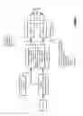
FIG. 4 is a flowchart showing an exemplary implementation of a gear detection algorithm according to an embodiment of the second aspect of the present invention;
FIG. 5 is a flowchart showing an exemplary implementation of a reverse gear detection algorithm according to an embodiment of the present invention;
FIG. 6 is a flowchart showing an exemplary method for determining the coasting state of the vehicle;
FIG. 7 shows an exemplary display of a navigation device indicating a shift-up advice following a determination that the driver is not in the optimal gear; and
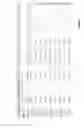
FIG. 8 is an illustration of an exemplary report as viewable on the computer of the fleet manager showing the over-revving performance metric for a plurality of trips made by a vehicle or driver.
DETAILED DESCRIPTION OF THE PREFERRED EMBODIMENTS
Embodiments of the invention are directed to methods and systems for monitoring the performance of drivers of vehicles over one or more journeys, and methods and systems for providing feedback to a driver in order to promote more economical driving.
An system for proving driver feedback is shown in FIG. 1. As shown in FIG. 1, the driver feedback comprises two components: feedback on current or historic driving performance (to be studied by the driver before beginning a trip or after having completed a trip); and advice on how driving styles can be modified to achieve more economical driving (which is typically given during a trip). The advice may comprise advice on an optimal or “green” speed to achieve maximum economical results; times/areas when “coasting” is possible; gear choice and when to change gear; etc. The feedback may comprise counts of events with harsh acceleration or declaration, speeding events (with respect to the speed limit and/or green speed), inefficient gear changes (over-revving), etc. The feedback may also comprise indicators as to how current and/or historic driving performance equates to predetermined goals, which may be set by the driver or may be set remotely by a fleet manager.
The invention is directed to the generation of a new performance indicator for use in providing driver feedback, and to methods for determining data for use in the generation of such a performance indicator. A summary of the each of the aspects of the invention is given below:
-
- The determination of a list of available gears in a geared vehicle, including a vehicle's highest (or maximum) gear, using vehicle speed and engine speed (rpm) values obtainable, for example, over a vehicle's on-board diagnostics (OBD) port
- The use of the determined list of available gears, together with current vehicle speed and engine speed values obtained, e.g. from the vehicle's OBD port, to determine a current gear
- The determination of whether a driver is coasting with braking or coasting without braking, based on the use of a vehicle's fuel rate and engine speed to detect whether the vehicle is coasting, either ‘coasting in gear’ or ‘coasting in neutral’
- The determination of an over-revving metric (or performance indicator) based on the amount of the time driven, in relation to the total driving time of the trip, when the engine speed is too high and the vehicle is not in the highest (or maximum gear). This over-revving metric can also be referred to as a score indicating the amount of time during a journey on a road network that a geared vehicle is driven in an optimal gear
System Architecture
The vehicle may be of any type of vehicle including a conventional (fossil fuel) powered vehicle, e.g. petrol or diesel, a hybrid vehicle, a hydrogen powered vehicle, a fuel cell powered vehicle or an electric vehicle. Embodiments of the invention will be described with reference to a vehicle having an engine (or drive unit) operative at an engine speed and fuel being supplied to the engine (or being consumed by the engine) at a fuel rate. It will, however, be realised that these terms may be construed accordingly to encompass the aforementioned types of vehicles.
The system of the invention is exemplified by FIG. 2 in which the vehicle can include: an on-board diagnostics (OBD) adapter; a vehicle tracking device; and a navigation device. The vehicle tracking device can be arranged to communicate with a server, which in turn is arranged to communicate with the navigation device in the vehicle and a computer, such as in the base of operations of the fleet manager. While the system the system shows three distinct devices in the vehicle: the OBD adapter; the vehicle tracking device and the navigation device, it will be appreciated that the vehicular components of the system can be shared between a greater number or a fewer number of devices as desired. Similarly, while FIG. 2 shows data being transmitted to the server only from the vehicle tracking device, in other embodiments data can be sent to the server from any of the vehicular devices as desired. The functionality of each of the components shown in FIG. 2 will now be described in more detail.
OBD Adapter:
The adapter device comprises an interface unit for communicating with one or more systems of the vehicle. The interface unit may be removably coupleable to an OBD port of the vehicle to receive data indicative of one or more parameters associated with the vehicle. The OBD port provides the one or more parameters to the interface unit from a communication bus of the vehicle. It will be realised, however, that the interface unit may communicate with the vehicle via other connections such as a via a wireless connection. The adapter device is therefore preferably configured to collect data from the OBD port in the vehicle, such as engine speed (rpm), vehicle speed, and to determine other information derived from such OBD data, such as the current gear, maximum gear, fuel consumption, etc, and to deliver the data to the vehicle tracking device. In other words, the data transmitted, in a wired and/or wireless manner, to the vehicle tracking device is indicative of a current state of the vehicle. It will be appreciated, however, that the speed of the vehicle may be determined in other ways, such as via received wireless location determining signals.
Vehicle Tracking Device:
The tracking device comprises a position determining device, such as a global navigation satellite system (GNSS) receiver, e.g. GPS or GLONASS. It will be appreciated, however, that other means may be used, such as using the mobile telecommunications network, surface beacons or the like. The positioning determining device generates tracking data, such as time-stamped positions, indicative of the change in position of the device over time. The tracking device further comprises one or more communication devices that are arranged to communicate with the OBD adapter, the navigation device and the server, either using a wired or wireless connection. The one or more communication devices can comprise a short range wireless transceiver, such as a Bluetooth transceiver, e.g. for communicating with the OBD adapter and the navigation device, and can comprise a mobile telecommunications transceiver, such as a GPRS or GSM transceiver, e.g. for communicating with the server. The tracking device further comprises at least one processor arranged to aggregate certain data for use in the subsequent generation of certain performance indicators (as discussed in more detail below), e.g. an over-revving performance indicator. For over-revving, the tracking device monitors the engine speed (obtained from the OBD adapter) and generates over-revving events.
Navigation Device:
The navigation device comprises at least one processor and a display device. The navigation device may be capable of one or more of: calculating a route to be travelled to a desired destination; and providing navigation instructions to guide the driver along a calculated route to reach a desired destination. The at least one processor is arranged to cause performance indicators (e.g.
obtained from the server) to be displayed on the display device, e.g. before, during and/or after a trip. The at least one processor can be further arranged to display indicators on the display device, such as an indicator to change up in gear, e.g. if it is determined that the vehicle is not currently in the maximum gear.
Server:
The server comprises at least one processor and a communications device for communicating with one of more of the vehicular devices, preferably the vehicle tracking device. The at least one processor is arranged to calculate at least one performance indicator, e.g. the over-revving indicator, for a trip.
Computer:
The computer is in communication with the server, and is used by a fleet manager to review the performance of the drivers of their fleet of vehicles based on the determined performance indicators.
Gear Detection
According to embodiments of the invention, there is provided methods and systems of determining gears of geared vehicle using vehicle speed and engine speed ratios of the vehicle, e.g. obtained over the OBD port of the vehicle using the OBD adapter device. The engine speed is typically represented using the unit rpm (revolutions per minute), which is a measure of the frequency of rotation of the engine. In standard gearboxes the rpm-speed ratios are expected to be constant for each gear, and thus having a list of all ratios would allow a currently engaged gear to be determined using a currently determined rpm-speed ratio.
A first embodiment uses a histogram based approach. In this embodiment, each of a plurality of speed-rpm ratios is assigned to an appropriate speed-rpm ratio bin (from among a plurality of speed-rpm ratio bins) to generate a histogram. A thresholding process can be applied to the histogram to identify a plurality of peaks, each peak being a speed-rpm ratio that relates to an engaged gear of the vehicle. These identified peaks can then be added to a gear table that has a plurality of entries, each entry being associated with an available gear of the vehicle and the speed-rpm ratio determined from the peak. An example of a histogram that is generated according to this embodiment is shown in FIG. 3. An advantage of this embodiment is that a currently engaged gear can be determined from a single sampled rpm-speed value. However, for example, some gears of the vehicle, e.g. reverse gear or first gear, may be rarely used and can be hard to identify. The method can also be difficult to implement if used in an OBD adapter (or other embedded device) which often has limited computer memory and processing resources, since the histogram table can be relatively large (depending on its level of granularity).
A second embodiment uses a continuous adaptation approach. In this embodiment, a plurality of successive speed-rpm ratios are obtained, and a determination made of a consistency measure indicative of a variation in the plurality of ratios. If consistency measure is within a predetermined limit, i.e. the successive ratios are effectively constant, then the observed ‘constant’ ratio can be said to be a result of a gear being engaged. A ratio found this way can be added as a new entry to a pre-existing gear table, or if similar to an existing entry used to fine-tune the speed-rpm ratio associated with the appropriate gear. Advantages of this embodiment are that the method is less impacted by noise often found in the data obtained from the OBD port, since the method is analysing relatively small sets of successive samples. Furthermore, the method requires less computational memory and processing resources in comparison to the first embodiment, and thus can be implemented more easily in an OBD adapter (or other embedded device).
An exemplary detailed implementation a gear detection algorithm according to the second embodiment is shown in FIG. 4. In this implementation the gear table is updated whenever the rpm-speed ratio is constant within a certain tolerance for a certain amount of samples. The current gear is returned whenever the rpm-speed ratio is constant with a certain (e.g. less strict) tolerance for a certain amount of samples. In this embodiment, gear ratios need to be detected multiple times to be considered stable. Unstable gear ratios are not taken into account when returning the current gear. A cyclic clean-up is used to remove unstable gear ratios.
Other improvements to the method of the second embodiment to ensure the gear table is accurate can include the use of:
-
- acceleration data from one or more accelerometers, since acceleration in a forward direction makes it more likely that a gear is engaged;
- other data from the OBD port, such as engine load, pedal position, etc
- speed data, since an increase in speed is again indicative that a gear is engaged.
As will be appreciated, the method of the second embodiment exemplified in FIG. 4 does not allow for the accurate detection of the reverse gear. This is because the reverse gear is typically only engaged for a short period of time. Although it can, in some instances, be mistakenly identified as an additional gear between gear 1 and gear 2, which can cause inaccuracies when detecting the current gear. A method of accurately detecting the reverse gear can use acceleration data and speed data, e.g. as shown in FIG. 5. In this embodiment, a driving direction of the vehicle can be determined by identifying whether there is positive or negative acceleration after a period of zero speed; a positive acceleration indicating a forwards driving direction, and a negative acceleration indicating a backwards driving direction.
Thus, the invention encompasses a method of determining a current gear of a geared vehicle. The method can comprise receiving a speed-rpm ratio of the vehicle based on a speed of the vehicle and a corresponding rpm of a drive unit of the vehicle, e.g. using an OBD adapter connected to the OBD port of the vehicle. A difference is preferably calculated between the speed-rpm ratio and an available speed-rpm ratio corresponding to a predetermined available gear of the vehicle. A determination is preferably made that the speed-rpm ratio corresponds to an available gear if the difference is within a predetermined tolerance limit; this available gear then being assigned as the current gear. The predetermined available gears are taken from a gear table created in accordance with one of the first and second methods described above.
Coasting
According to embodiments of the invention, there is provided methods and systems for determining whether a driver of a vehicle is coasting during a trip. The term “coasting” in this instance means that the driver has lifted their foot off the accelerator (or gas pedal) to reduce the vehicle speed, such that the vehicle is allowed to naturally decelerate or to roll without being under power. In this way, a fuel economy of the vehicle may be improved.
The detection of coasting is preferably based at least on fuel rate and engine speed, e.g. as obtained by the OBD adapter. Optionally, the detection of coasting is further based on the vehicle speed. For example, coasting may only be detected when the vehicle speed is above a predetermined threshold, such as 20 km/h.
In embodiments, the fuel rate when idling (the “idling rate”) and the engine speed when idling (the “idling rpm”) is determined for a vehicle, and these values are used to detect periods of coasting by the vehicle. The idling rate and idling rpm are preferably regularly updated at periods of standstill, e.g. each time the vehicle is stopped for a predetermined period of time with the engine running, such that the values reflect the current status of the vehicle. For example, the values may change over time based on the maintenance status of the vehicle.
In embodiments, a determination is continuously made during a trip by a vehicle as to whether the vehicle is in one of the following states: “no coasting”; “coasting in gear”; or “coasting in neutral”. An exemplary method for determining the state of the vehicle is shown in FIG. 6, and uses as inputs: the current speed of the vehicle; the current fuel rate of the vehicle; and the current engine speed of the vehicle. The threshold values TS1, TF1, TF2 and TE1 are all predetermined. The thresholds TF1 and TF2 are each based on the determined idling rate for the vehicle; TF1 typically be a less than the idling rate, while TF2 is typically more the idling rate. Similarly, the threshold TE1 is based on the determined idling rpm for the vehicle; TE1 typically being more than the idling rpm. The method of FIG. 6 is based on the assumptions that the driver will not press the accelerator (or gas pedal) when coasting and that coasting can be performed with an inserted gear or when in neutral.
Over-revving Performance Indicator
The over-revving performance indicator is based on the recognition that, in general, fuel consumption of a vehicle is reduced by keeping the engine speed as low as possible during a trip. Accordingly, a driver should ideally shift up to a higher gear early in order to keep the engine speed low and to prevent high-revving.
In embodiments, the performance indicator is based on the relative time of high-revving during a trip to the “real” driving time (i.e. the time at which the vehicle is not standing still). As will be discussed in more detail below, high-revving is defined as times when the engine speed exceeds a predetermined threshold and/or when the vehicle is not using the highest (or maximum) gear, e.g. determined by the OBD adapter using one of the methods described above. The predetermined threshold can be based on the type of fuel used by the vehicle, e.g. with a different threshold used for a petrol (or gasoline) engine than for a diesel engine. Optionally, periods of high-revving are additionally based on times when the vehicle is not coasting. In embodiments, the determination of high-revving is made on the vehicle tracking device based on data received from the OBD adapter, e.g. engine speed, current gear, maximum gear, etc.
In embodiments, a shift up advice can be shown on the display of the navigation device to inform the driver that they should change to a higher gear. Such an advice can be displayed when a period of high-revving, e.g. as defined above, is detected. In embodiments, the determination of high-revving that triggers the display of the shift up advice is made on the vehicle tracking device, and a message sent to the navigation display to display the advice. An example of a graphical icon that can be shown to the driver when it is determined that the vehicle is not in an optimal gear can be seen in FIG. 7. The graphical icon 70 will be shown, either until the message is cancelled by the driver touching the region 74, or until it is detected that the driver has followed the advice and is now travelling in the optimal gear. An icon 72 showing a representation of the total driving score of the driver is also displayed on the device.
An exemplary description of the manner by which high-revving is detected is as follows:
Input:
- engine speed, n
- current gear, cg
- maximum gear, mg
- fuel type, fuel_type
- stand still state, stand_still
- coasting state, coasting
Output:
- driving time, dt
- high-revving time, hrt
Algorithm:
- the driving time dt is calculated by summing the time at which stand_still is false
- the high-revving time hrt is calculated by summing the time at which: cg<mg; n>N, wherein N is a threshold based on fuel_type; and coasting is false
The over-revving performance indicator is calculated based on the determined values of driving time dt and high-revving time hrt.
An exemplary report as viewable on the computer of the fleet manager showing the over-revving performance metric for a plurality of trips made by a vehicle or driver is shown in FIG. 8. For example, in one journey on 1 October between 08h10 and 09h10 (total journey time of 49 minutes and 46 seconds), the driver drove in the optimal gear for 47 minutes and 13 seconds. Therefore the driver has achieved a score of 94% for that particular journey. The report also shows that during the times at which the driver was not in the optimal gear, then the engine speed, i.e. the speed of the vehicle drive unit, was on average 399 rom too high. The report also shows an overall score for the driver across all journeys of 6.7, wherein the driver has driven in the optimal gear for 94.3% of all journeys and, when not in optimal gear, was on average 380 rpm too high.
Any of the methods in accordance with the invention as described above may be implemented at least partially using software, e.g. computer programs. The present invention thus also extends to a computer program comprising computer readable instructions executable to perform, or to cause a computing device, e.g. OBD adapter, vehicle tracking device, navigation device, server, etc, to perform, a method according to any of the above described aspects or embodiments of the invention. The invention correspondingly extends to a computer software carrier comprising such software which, when used to operate a system or apparatus comprising data processing means causes, in conjunction with said data processing means, said apparatus or system to carry out the steps of the methods of the present invention. Such a computer software carrier could be a non-transitory physical storage medium such as a ROM chip, CD ROM or disk, or could be a signal such as an electronic signal over wires, an optical signal or a radio signal such as to a satellite or the like. The present invention provides a machine readable medium containing instructions which when read by a machine cause the machine to operate according to the method of any of the aspects or embodiments of the invention.
Claims
1. A method of providing an indication to a driver of a geared vehicle that the vehicle is not in an optimal gear, comprising:
determining a current gear of the vehicle;
determining a current speed of a drive unit of the vehicle;
determining a coasting state of the vehicle; and
providing an indication to the driver of the vehicle that the vehicle is not in an optimal gear when: (i) the determined current speed of the drive unit is greater than a predetermined threshold; (ii) the determined current gear of the vehicle is less than a maximum gear of the vehicle; and (iii) the determined coasting state of the vehicle indicates the vehicle is not currently coasting, wherein the coasting state of the vehicle is determined based upon at least one of the current speed of the drive unit of the vehicle and a fuel usage rate of the drive unit of the vehicle.
2. The method of claim 1, wherein the predetermined threshold is based on a fuel type used by the drive unit of the vehicle.
3. The method of claim 2, wherein the fuel type is one of diesel or petrol.
4. The method of claim 3, wherein a first predetermined threshold is used for a petrol drive unit, and a second predetermined threshold is used for a diesel drive unit, and wherein the first predetermined threshold is higher than the second predetermined threshold.
5. The method of claim 1, wherein at least one of the current gear of the vehicle and the current speed of the drive unit is received from a remote device.
6. The method of claim 1, wherein the determination of the current gear of the vehicle comprises:
receiving a speed-rpm ratio of the vehicle, based on a speed of the vehicle and a corresponding speed of the drive unit of the vehicle;
evaluating a difference between the speed-rpm ratio and a speed-rpm ratio from an entry in a gear table, said gear table comprising a plurality of entries, each entry associating an available gear of the geared vehicle with a speed-rpm ratio; and
determining that the current gear of the vehicle is the available gear of the entry in the gear table when the difference is within a predetermined threshold.
7. The method of claim 6, wherein the maximum gear of the vehicle is determined from the gear table.
8. (canceled)
9. The method of claim 1, wherein providing an indication to the driver that the vehicle is not in an optimal gear comprises at least one of:
displaying a graphical icon on a display device within the vehicle; providing an audio warning to the driver; and providing an a haptic warning to the driver.
10. The method of claim 1, further comprising:
determining a first time indicative of the total driving time of a journey on road network;
determining a second time indicative of the driving time during the journey that the vehicle was not in an optimal gear; and
determining a score indicative of the amount of time during the journey that the vehicle was driven in an optimal gear based on the first and second times.
11. A method of determining a score indicative of the amount of time during a journey on a road network that a geared vehicle is driven in an optimal gear, comprising:
determining a first time indicative of the total driving time of the journey;
determining a second time indicative of the driving time during the journey that the vehicle was not in an optimal gear, wherein the vehicle is not in an optimal gear when: (i) a current speed of the drive unit of the vehicle is greater than a predetermined threshold; (ii) a current gear of the vehicle is less than a maximum gear of the vehicle; and (iii) the vehicle is not currently in a coasting state; and
determining a score indicative of the amount of time during the journey that the vehicle was driven in an optimal gear based on the first and second times.
12. The method of claim 11, wherein the determination of the score is based on a ratio of the second time to the first time.
13. The method of claim 11, comprising at least one of: displaying a representation of the score on a display device within the vehicle; and transmitting the determined score for display on a remote device.
14. An apparatus for providing an indication to a driver of a geared vehicle that the vehicle is not in an optimal gear, comprising at least one processor and a memory containing instructions that, when executed by the at least one processor, cause the apparatus to:
determine a current gear of the vehicle;
determine a current speed of a drive unit of the vehicle;
determine a coasting state of the vehicle; and
provide an indication to the driver of the vehicle that the vehicle is not in an optimal gear when:
(i) the determined current speed of the drive unit is greater than a predetermined threshold; (ii) the determined current gear of the vehicle is less than a maximum gear of the vehicle; and (iii) the determined coasting state of the vehicle indicates the vehicle is not currently coasting, wherein the coasting state of the vehicle is determined based upon at least one of the current speed of the drive unit of the vehicle and a fuel usage rate of the drive unit of the vehicle.
15. An apparatus for determining a score indicative of the amount of time during a journey on a road network that a geared vehicle is driven in an optimal gear, comprising at least one processor and a memory containing instructions that, when executed by the at least one processor, cause the apparatus to:
determine a first time indicative of the total driving time of the journey;
determine a second time indicative of the driving time during the journey that the vehicle was not in an optimal gear, wherein the vehicle is not in an optimal gear when: (i) a current speed of the drive unit of the vehicle is greater than a predetermined threshold; (ii) a current gear of the vehicle is less than a maximum gear of the vehicle; and (iii) the vehicle is not currently in a coasting state; and
determine a score indicative of the amount of time during the journey that the vehicle was driven in an optimal gear based on the first and second times.
16. The apparatus of claim 14, wherein the apparatus is a vehicle tracking device or a portable navigation device.
17. The apparatus of claim 14, comprising a receiver, optionally a wireless receiver, to receive at least one of the current gear of the vehicle and the current speed of the drive unit from a remote device coupled to an on-board diagnostics (OBD) port of the vehicle.
18. A computer program product comprising instructions which, when executed by at least one processor of an apparatus comprising at least one processor, cause the apparatus to operate according to the method of claims 1.
19. A non-transitory computer readable medium having the computer program product of claim 18 stored therein.
Images & Drawings included:


Sources:
- United States Patent and Trademark Office - verify current appl. status at the USPTO↗
Recent applications in this class:
- » 20250060034 2025-02-20
METHOD OF GUIDING VEHICLE SHIFT TIMING - » 20210054929 2021-02-25
cycle derailleur with setting indicator - » 20200141489 2020-05-07
Gear indicator illumination unit - » 20190293177 2019-09-26
Control Device in a Motor Vehicle for Outputting a Gear-Shift Recommendation - » 20190219167 2019-07-18
Control device for vehicle and control method for vehicle - » 20190093766 2019-03-28
Gear position detecting device - » 20180172156 2018-06-21
Method and device for gear shift assistance - » 20180058579 2018-03-01
Shift-by-wire module illumination strategy for vehicle - » 20170284543 2017-10-05
Shift change practice device - » 20170051828 2017-02-23
Method and device for prompting bicycle gear shifting
Recent applications for this Assignee:
- » 20170322047 2017-11-09
Apparatus and method for providing an advised driving speed - » 20170316686 2017-11-02
Apparatus and method for vehicle economy improvement - » 20170305435 2017-10-26
Apparatus and method for vehicle economy improvement - » 20170261336 2017-09-14
Accelerometer system and method - » 20160196697 2016-07-07
Method and apparatus for vehicle usage recording - » 20160146336 2016-05-26
Apparatus and method for gear detection - » 20160144713 2016-05-26
Apparatus and method for determining an advised driving speed - » 20160125669 2016-05-05
Wireless communication devices - » 20160125668 2016-05-05
Wireless communication devices - » 20160049018 2016-02-18
Engine state detection device