Perforated ceramic matrix composite ply, ceramic matrix composite article, and method for forming ceramic matrix composite article
US20170320232A1
2017-11-09
15/146,288
2016-05-04
✅ Patent granted
US 10,207,471 B2
2019-02-19
-
-
Jeffrey A Vonch
Ernest G. Cusick | Frank A. Landgraff
2036-10-29
Abstract:
A ceramic matrix composite article, method for forming the article, and perforated ply which may be incorporated therein are disclosed. The article includes at least one shell ply forming an exterior wall having first and second portions and defining a plenum. An annular brace formed of at least one structural support ply is disposed within the plenum, including a first integral portion integral with and part of the first portion of the exterior wall, a first curved portion extending from the first integral portion and curving across the article plenum to the second portion of the exterior wall, a second integral portion integral with and part of the second portion of the exterior wall, a second curved portion extending from the second integral portion and curving across the article plenum to the first curved portion, and an overlap in which the first and second curved portions are integral.
Assignee:
- GENERAL ELECTRIC COMPANY 28,775 🇺🇸 Schenectady, NY, United States
Applicant:
Interested in similar patents?
Get notified when new applications in this technology area are published.
Classification:
B28B1/001 » CPC main
Producing shaped prefabricated articles from the material Rapid manufacturing of 3D objects by additive depositing, agglomerating or laminating of material
B28B1/00 IPC
Producing shaped prefabricated articles from the material
B33Y80/00 » CPC further
Products made by additive manufacturing
B33Y10/00 » CPC further
Processes of additive manufacturing
B32B3/263 » CPC further
Layered products comprising a layer with external or internal discontinuities or unevennesses, or a layer of non-planar form ; Layered products having particular features of form characterised by a particular shape of the outline of the cross-section of a continuous layer; characterised by a layer with cavities or internal voids ; characterised by an apertured layer characterised by a layer having non-uniform thickness
B32B3/266 » CPC further
Layered products comprising a layer with external or internal discontinuities or unevennesses, or a layer of non-planar form ; Layered products having particular features of form characterised by a particular shape of the outline of the cross-section of a continuous layer; characterised by a layer with cavities or internal voids ; characterised by an apertured layer characterised by an apertured layer, the apertures going through the whole thickness of the layer, e.g. expanded metal, perforated layer, slit layer regular cells
C04B37/005 » CPC further
Joining burned ceramic articles with other burned ceramic articles or other articles by heating by means of an interlayer consisting of a combination of materials selected from glass, or ceramic material with metals, metal oxides or metal salts consisting of glass or ceramic material
F01D5/147 » CPC further
Blades; Blade-carrying members ; Heating, heat-insulating, cooling or antivibration means on the blades or the members; Blades; Form or construction Construction, i.e. structural features, e.g. of weight-saving hollow blades
F01D5/188 » CPC further
Blades; Blade-carrying members ; Heating, heat-insulating, cooling or antivibration means on the blades or the members; Blades; Form or construction; Hollow blades, i.e. blades with cooling or heating channels or cavities ; Heating, heat-insulating or cooling means on blades; Convection cooling with an insert in the blade cavity to guide the cooling fluid, e.g. forming a separation wall
F01D5/189 » CPC further
Blades; Blade-carrying members ; Heating, heat-insulating, cooling or antivibration means on the blades or the members; Blades; Form or construction; Hollow blades, i.e. blades with cooling or heating channels or cavities ; Heating, heat-insulating or cooling means on blades; Convection cooling with an insert in the blade cavity to guide the cooling fluid, e.g. forming a separation wall the insert having a tubular cross-section, e.g. airfoil shape
F01D5/282 » CPC further
Blades; Blade-carrying members ; Heating, heat-insulating, cooling or antivibration means on the blades or the members; Blades; Selecting particular materials; Particular measures relating thereto; Measures against erosion or corrosion Selecting composite materials, e.g. blades with reinforcing filaments
F01D25/005 » CPC further
Component parts, details, or accessories, not provided for in, or of interest apart from, other groups Selecting particular materials
B32B2260/023 » CPC further
Layered product comprising an impregnated, embedded, or bonded layer wherein the layer comprises an impregnation, embedding, or binder material; Composition of the impregnated, bonded or embedded layer; Fibrous or filamentary layer Two or more layers
B32B2260/04 » CPC further
Layered product comprising an impregnated, embedded, or bonded layer wherein the layer comprises an impregnation, embedding, or binder material Impregnation, embedding, or binder material
B32B2262/10 » CPC further
Composition or structural features of fibres which form a fibrous or filamentary layer or are present as additives Inorganic fibres
B32B2262/105 » CPC further
Composition or structural features of fibres which form a fibrous or filamentary layer or are present as additives; Inorganic fibres Ceramic fibres
B32B2262/106 » CPC further
Composition or structural features of fibres which form a fibrous or filamentary layer or are present as additives; Inorganic fibres Carbon fibres, e.g. graphite fibres
B32B2305/07 » CPC further
Condition, form or state of the layers or laminate Parts immersed or impregnated in a matrix
B32B2305/076 » CPC further
Condition, form or state of the layers or laminate; Parts immersed or impregnated in a matrix Prepregs
B32B2305/08 » CPC further
Condition, form or state of the layers or laminate Reinforcements
B32B2313/00 » CPC further
Elements other than metals
B32B2313/02 » CPC further
Elements other than metals Boron
B32B2313/04 » CPC further
Elements other than metals Carbon
B32B2603/00 » CPC further
Vanes, blades, propellers, rotors with blades
C04B35/521 » CPC further
Shaped ceramic products characterised by their composition ; Ceramics compositions ; Processing powders of inorganic compounds preparatory to the manufacturing of ceramic products based on non-oxide ceramics based on carbon, e.g. graphite obtained by impregnation of carbon products with a carbonisable material
C04B2237/38 » CPC further
Aspects relating to ceramic laminates or to joining of ceramic articles with other articles by heating; Composition of layers of ceramic laminates or of ceramic or metallic articles to be joined by heating, e.g. Si substrates; Ceramic Fiber or whisker reinforced
C04B2237/385 » CPC further
Aspects relating to ceramic laminates or to joining of ceramic articles with other articles by heating; Composition of layers of ceramic laminates or of ceramic or metallic articles to be joined by heating, e.g. Si substrates; Ceramic; Fiber or whisker reinforced Carbon or carbon composite
C04B2237/61 » CPC further
Aspects relating to ceramic laminates or to joining of ceramic articles with other articles by heating; Processing aspects relating to ceramic laminates or to the joining of ceramic articles with other articles by heating Joining two substrates of which at least one is porous by infiltrating the porous substrate with a liquid, such as a molten metal, causing bonding of the two substrates, e.g. joining two porous carbon substrates by infiltrating with molten silicon
C04B2237/84 » CPC further
Aspects relating to ceramic laminates or to joining of ceramic articles with other articles by heating; Processing aspects relating to ceramic laminates or to the joining of ceramic articles with other articles by heating Joining of a first substrate with a second substrate at least partially inside the first substrate, where the bonding area is at the inside of the first substrate, e.g. one tube inside another tube
F01D5/284 » CPC further
Blades; Blade-carrying members ; Heating, heat-insulating, cooling or antivibration means on the blades or the members; Blades; Selecting particular materials; Particular measures relating thereto; Measures against erosion or corrosion Selection of ceramic materials
F05D2240/12 » CPC further
Components; Stators Fluid guiding means, e.g. vanes
F05D2240/128 » CPC further
Components; Stators; Fluid guiding means, e.g. vanes Nozzles
F05D2240/14 » CPC further
Components; Stators Casings or housings protecting or supporting assemblies within
F05D2240/15 » CPC further
Components; Stators Heat shield
F05D2240/301 » CPC further
Components; Rotors; Characteristics of rotor blades, i.e. of any element transforming dynamic fluid energy to or from rotational energy and being attached to a rotor Cross-sectional characteristics
F05D2250/141 » CPC further
Geometry; Two-dimensional elliptical circular
F05D2250/231 » CPC further
Geometry; Three-dimensional prismatic cylindrical
F05D2300/2112 » CPC further
Materials; Properties thereof; Oxide or non-oxide ceramics; Oxide ceramics Aluminium oxides
F05D2300/224 » CPC further
Materials; Properties thereof; Oxide or non-oxide ceramics; Non-oxide ceramics Carbon, e.g. graphite
F05D2300/2261 » CPC further
Materials; Properties thereof; Oxide or non-oxide ceramics; Non-oxide ceramics; Carbides of silicon
F05D2300/6033 » CPC further
Materials; Properties thereof; Properties or characteristics given to material by treatment or manufacturing; Composites; e.g. fibre-reinforced Ceramic matrix composites [CMC]
Y10T428/131 » CPC further
Stock material or miscellaneous articles; Hollow or container type article [e.g., tube, vase, etc.] Glass, ceramic, or sintered, fused, fired, or calcined metal oxide or metal carbide containing [e.g., porcelain, brick, cement, etc.]
Y10T428/1314 » CPC further
Stock material or miscellaneous articles; Hollow or container type article [e.g., tube, vase, etc.]; Glass, ceramic, or sintered, fused, fired, or calcined metal oxide or metal carbide containing [e.g., porcelain, brick, cement, etc.] Contains fabric, fiber particle, or filament made of glass, ceramic, or sintered, fused, fired, or calcined metal oxide, or metal carbide or other inorganic compound [e.g., fiber glass, mineral fiber, sand, etc.]
Y10T428/24298 » CPC further
Stock material or miscellaneous articles; Structurally defined web or sheet [e.g., overall dimension, etc.] including aperture Noncircular aperture [e.g., slit, diamond, rectangular, etc.]
Y10T428/24322 » CPC further
Stock material or miscellaneous articles; Structurally defined web or sheet [e.g., overall dimension, etc.] including aperture Composite web or sheet
Y10T428/24331 » CPC further
Stock material or miscellaneous articles; Structurally defined web or sheet [e.g., overall dimension, etc.] including aperture; Composite web or sheet including nonapertured component
Y10T428/24612 » CPC further
Stock material or miscellaneous articles; Structurally defined web or sheet [e.g., overall dimension, etc.] including variation in thickness Composite web or sheet
Y10T428/24744 » CPC further
Stock material or miscellaneous articles; Structurally defined web or sheet [e.g., overall dimension, etc.] Longitudinal or transverse tubular cavity or cell
F01D5/14 IPC
Blades; Blade-carrying members ; Heating, heat-insulating, cooling or antivibration means on the blades or the members; Blades Form or construction
F01D5/18 IPC
Blades; Blade-carrying members ; Heating, heat-insulating, cooling or antivibration means on the blades or the members; Blades; Form or construction Hollow blades, i.e. blades with cooling or heating channels or cavities ; Heating, heat-insulating or cooling means on blades
F01D5/28 IPC
Blades; Blade-carrying members ; Heating, heat-insulating, cooling or antivibration means on the blades or the members; Blades Selecting particular materials; Particular measures relating thereto; Measures against erosion or corrosion
C04B35/76 » CPC further
Shaped ceramic products characterised by their composition ; Ceramics compositions ; Processing powders of inorganic compounds preparatory to the manufacturing of ceramic products; Ceramic products containing macroscopic reinforcing agents containing shaped metallic materials Fibres, filaments, whiskers, platelets, or the like
B32B5/26 » CPC further
Layered products characterised by the non- homogeneity or physical structure, i.e. comprising a fibrous, filamentary, particulate or foam layer; Layered products characterised by having a layer differing constitutionally or physically in different parts characterised by the presence of two or more layers which are next to each other and are fibrous, filamentary, formed of particles or foamed one layer being a fibrous or filamentary layer another layer also being fibrous or filamentary
B32B7/04 » CPC further
Layered products characterised by the relation between layers; Layered products characterised by the relative orientation of features between layers, or by the relative values of a measurable parameter between layers, i.e. products comprising layers having different physical, chemical or physicochemical properties; Layered products characterised by the interconnection of layers Interconnection of layers
B32B18/00 » CPC further
Layered products essentially comprising ceramics, e.g. refractory products
C04B37/00 IPC
Joining burned ceramic articles with other burned ceramic articles or other articles by heating
B32B3/26 IPC
Layered products comprising a layer with external or internal discontinuities or unevennesses, or a layer of non-planar form ; Layered products having particular features of form characterised by a particular shape of the outline of the cross-section of a continuous layer; characterised by a layer with cavities or internal voids ; characterised by an apertured layer
C04B35/64 » CPC further
Shaped ceramic products characterised by their composition ; Ceramics compositions ; Processing powders of inorganic compounds preparatory to the manufacturing of ceramic products; Forming processes; Processing powders of inorganic compounds preparatory to the manufacturing of ceramic products Burning or sintering processes
F01D25/00 IPC
Component parts, details, or accessories, not provided for in, or of interest apart from, other groups
C04B35/52 » CPC further
Shaped ceramic products characterised by their composition ; Ceramics compositions ; Processing powders of inorganic compounds preparatory to the manufacturing of ceramic products based on non-oxide ceramics based on carbon, e.g. graphite
C04B35/10 » CPC further
Shaped ceramic products characterised by their composition ; Ceramics compositions ; Processing powders of inorganic compounds preparatory to the manufacturing of ceramic products based on oxide ceramics based on aluminium oxide
F01D25/14 » CPC further
Component parts, details, or accessories, not provided for in, or of interest apart from, other groups; Cooling ; Heating; Heat-insulation Casings modified therefor
B32B1/08 » CPC main
Layered products having a general shape other than plane Tubular products
C04B35/565 » CPC further
Shaped ceramic products characterised by their composition ; Ceramics compositions ; Processing powders of inorganic compounds preparatory to the manufacturing of ceramic products based on non-oxide ceramics based on carbides or oxycarbides based on silicon carbide
F05D2260/201 » CPC further
Function; Heat transfer, e.g. cooling by impingement of a fluid
F01D25/12 » CPC further
Component parts, details, or accessories, not provided for in, or of interest apart from, other groups; Cooling ; Heating; Heat-insulation Cooling
Description
FIELD OF THE INVENTION
The present invention is directed to ceramic matrix composite (CMC) plies, CMC articles, and methods for forming CMC articles. More particularly, the present invention is directed to perforated CMC plies, CMC articles including integrated annular braces, and methods for forming CMC articles with integrated annular braces.
BACKGROUND OF THE INVENTION
Gas turbines are continuously being modified to provide increased efficiency and performance. These modifications include the ability to operate at higher temperatures and under harsher conditions, which often requires material modifications and/or coatings to protect components from such temperatures and conditions. As more modifications are introduced, additional challenges are realized.
One modification to increase performance and efficiency involves forming gas turbine components, such as, but not limited to, airfoils, buckets (blades), nozzles (vanes), shrouds, combustor liners, and heat shields from CMC. However, CMC components may be more susceptible to bending stresses and deformation than other structural materials such as superalloys.
Additionally, CMC is expensive, and paring sheets of CMC material to a required shape for a particular apparatus may produce significant amounts of CMC scrap. In addition, the paring process may introduce defects into the ply, and may require multiple paring steps to achieve a sufficiently precise conformation.
BRIEF DESCRIPTION OF THE INVENTION
In an exemplary embodiment, a CMC article includes at least one shell ply. The at least one shell ply forms an exterior wall of the CMC article and defines an article plenum within the exterior wall. The exterior wall includes a first portion and a second portion. The CMC article further includes a first annular brace disposed within the article plenum. The first annular brace includes a first integral portion, a first curved portion, a second integral portion, a second curved portion, and an overlap. The first integral portion is integral with and part of the first portion of the exterior wall. The first curved portion extends from the first integral portion and curves across the article plenum to the second portion of the exterior wall. The second integral portion is integral with and part of the second portion of the exterior wall. The second curved portion extends from the second integral portion and curves across the article plenum to the first curved portion. The first curved portion is integral with and part of the second curved portion in the overlap. The first annular brace is formed of at least one structural support ply.
In another exemplary embodiment, a perforated CMC ply includes a CMC composition and a plurality of apertures distributed across at least a portion of the ply. The CMC composition is selected from the group consisting of an aluminum oxide-fiber-reinforced aluminum oxide (Ox/Ox), a carbon-fiber-reinforced carbon (C/C), a carbon-fiber-reinforced silicon carbide (C/SiC), a silicon-carbide-fiber-reinforced silicon carbide (SiC/SiC), and combinations thereof. The plurality of apertures include aperture conformations selected from the group consisting of circles, ovals, ellipses, semicircles, crescents, triangles, squares, rectangles, annuli, chevrons, polygons, irregular shapes, rounded polygons, and combinations thereof. The ply includes a property of increased flexibility compared to a comparable ply lacking the plurality of apertures, and a property of increased consolidation, pyrolization, and densification efficiency compared to the comparable ply lacking the plurality of apertures.
In another exemplary embodiment, a method for forming a CMC article includes, disposing at least one structural support ply within an article plenum defined by at least one shell ply. The at least one structural support ply defines a first annular brace. The at least one shell ply forms an exterior wall of the CMC article having the article plenum within the exterior wall. The exterior wall includes a first portion and a second portion. A first integral portion of the at least one structural support ply is adjacent to and in contact with the first portion of the exterior wall. A first curved portion of the at least one structural support ply extends from the first integral portion and curves across the article plenum to the second portion of the exterior wall. A second integral portion of the at least one structural support ply is adjacent to and in contact with the second portion of the exterior wall. A second curved portion of the at least one structural support ply extends from the second integral portion and curves across the article plenum to the first curved portion, defining an overlap of the first curved portion and the second curved portion. The method further includes consolidating the at least one structural support ply and the at least one shell ply, pyrolizing the at least one structural support ply and the at least one shell ply, and densifying the at least one structural support ply and the at least one shell ply. Consolidating, pyrolizing, and densifying the at least one structural support ply and the at least one shell ply integrates the at least one structural support ply and the at least one shell ply where the at least one structural support ply contacts the at least one shell ply, and integrates the overlap of the at least one structural support ply.
Other features and advantages of the present invention will be apparent from the following more detailed description of the preferred embodiment, taken in conjunction with the accompanying drawings, which illustrate, by way of example, the principles of the invention.
BRIEF DESCRIPTION OF THE DRAWINGS
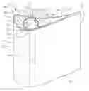
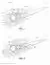
FIG. 1 is a cross-sectional view of a CMC article having one annular brace, according to an embodiment of the present disclosure.
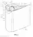
FIG. 2 is a perspective view of the CMC article of FIG. 1, according to an embodiment of the present disclosure.
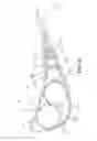
FIG. 3 is a cross-sectional view of a CMC article having two separated annular braces, according to an embodiment of the present disclosure.
FIG. 4 is an expanded partial cross-sectional view of a CMC article having two adjacent annular braces, according to an embodiment of the present disclosure.
FIG. 5 is an expanded partial cross-sectional view of a CMC article having two integrated annular braces, according to an embodiment of the present disclosure.
FIG. 6 is a cross-sectional view of a CMC article having five annular braces, according to an embodiment of the present disclosure.
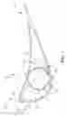
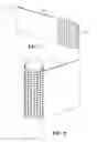
FIG. 7 is a perspective view of a perforated CMC ply, according to an embodiment of the present disclosure.
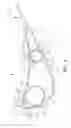
FIG. 8 is a perspective view of the perforated CMC ply of FIG. 7 wrapped around a ply-support mandrel, according to an embodiment of the present disclosure.
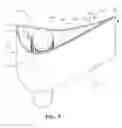
FIG. 9 is a perspective view of an unintegrated CMC article, according to an embodiment of the present disclosure.
Wherever possible, the same reference numbers will be used throughout the drawings to represent the same parts.
DETAILED DESCRIPTION OF THE INVENTION
Provided are CMC plies, CMC articles, and methods for forming CMC articles. Embodiments of the present disclosure, in comparison to processes not utilizing one or more features disclosed herein, decrease costs, increase process efficiency, increase strength, decrease deformation susceptibility, decrease weight, increase cooling flow, increase operating temperature limits, increase bending stress resistance, increases stiffness, increase ply flexibility, increase durability, increase operating lifetime, or a combination thereof.
Referring to FIG. 1, in one embodiment, a CMC article 100 includes at least one shell ply 102. The at least one shell ply 102 forms an exterior wall 104 of the CMC article 100 and defines an article plenum 106 within the exterior wall 104. The exterior wall 104 includes a first portion 108 and a second portion 110. The CMC article further includes a first annular brace 112 disposed within the article plenum 106. The first annular brace 112 includes a first integral portion 114, a first curved portion 116, a second integral portion 118, a second curved portion 120, and an overlap 122. The first integral portion 114 is integral with and part of the first portion 108 of the exterior wall 104. The first curved portion 116 extends from the first integral portion 114 and curves across the article plenum 106 to the second portion 110 of the exterior wall 104. The second integral portion 118 is integral with and part of the second portion 110 of the exterior wall 104. The second curved portion 120 extends from the second integral portion 118 and curves across the article plenum 106 to the first curved portion 116. The first curved portion 116 is integral with and part of the second curved portion 120 in the overlap 122. The first annular brace 112 is formed of at least one structural support ply 124.
As used herein, “integral with and part of” indicates that the references structures are of unitary construction, being of a piece, and are not merely adhered or bound together. In one embodiment, the at least one shell ply 102 and the at least one structural support ply 124 are consolidated and densified, and are free of adhesive and mechanical fasteners. As used herein, “free of adhesive and mechanical fasteners” specifically relates to a lack of adhesive and mechanical fasteners joining the at least one shell ply 102 to the at least one structural support ply 124, and does not prohibit in any way the usage of adhesives or mechanical fasteners to join the unitary at least one shell ply 102 and at least one structural support ply 124 to a separate structure with which the at least one shell ply 102 and at least one structural support ply 124 are not part of an integral with.
As used herein, “annular” indicates a shape which forms a complete loop, and which may be, but is not necessarily, generally circular, elliptical, or oval in aspect. The first annular brace may include any suitable cross-sectional conformation. In one embodiment, the suitable cross-sectional conformation may include, but is not limited to, a circle, an irregular circle, an ellipse, an irregular ellipse, an oval, an irregular oval, or a combination thereof. As used herein “irregular” refers to a shape which generally conforms to the described conformation but which includes local or general deviations from a standard geometrical understanding of the conformation.
The at least one shell ply 102 and the at least one structural support ply 124 may, independently, include, any suitable CMC composition. In one embodiment, the suitable CMC compositions include, but are not limited to, an aluminum oxide-fiber-reinforced aluminum oxide (Ox/Ox), a carbon-fiber-reinforced carbon (C/C), a carbon-fiber-reinforced silicon carbide (C/SiC), a silicon-carbide-fiber-reinforced silicon carbide (SiC/SiC), or a combination thereof.
The first annular brace 112 may define a first brace plenum 126 within the first annular brace 112. In one embodiment, the at least one structural support ply 124 of the first annular brace 112 includes a perforated CMC ply 128 including a plurality of apertures 130 between, and in fluid communication with, the article plenum 106 and the first brace plenum 126. The first brace plenum 126 may be in fluid communication with a cooling fluid source.
Referring to FIG. 2, the plurality of apertures 130 may include any suitable aperture conformation, including, but not limited to, circles (200), ovals, ellipses 202, semicircles 204, crescents, triangles 206, squares 208, rectangles, pentagons 210, annuli 212, chevrons, polygons, irregular shapes, rounded polygons 214, and combinations thereof.
Referring to FIG. 3, in one embodiment, the CMC article 100 further includes a second annular brace 300 disposed within the article plenum 106. The second annular brace 300 includes a first integral portion 114, a first curved portion 116, a second integral portion 118, a second curved portion 120, and an overlap 122. The first integral portion 114 is integral with and part of a third portion 302 of the exterior wall 104. The first curved portion 116 extends from the first integral portion 114 and curves across the article plenum 106 to the fourth portion 304 of the exterior wall 104. The second integral portion 118 is integral with and part of the fourth portion 304 of the exterior wall 104. The second curved portion 120 extends from the second integral portion 118 and curves across the article plenum 106 to the first curved portion 116. The first curved portion 116 is integral with and part of the second curved 120 portion in the overlap 122. The second annular brace 300 is formed of at least one structural support ply 124.
The second annular brace 300 may define a second brace plenum 306 within the second annular brace 300. In one embodiment, the at least one structural support ply 124 of the second annular brace 300 includes a perforated CMC ply 128 including a plurality of apertures 130 between, and in fluid communication with, the article plenum 106 and the second brace plenum 306.
Referring to FIGS. 3-5, in one embodiment (FIG. 3), the first annular brace 112 is remote from the second annular brace 300. In another embodiment (FIG. 4), the first annular brace 112 is adjacent to but distinct from the second annular brace 300. In yet another embodiment (FIG. 5), the first annular brace 112 is adjacent to the second annular brace 300, and the CMC article further including a contact region 500 in which the second curved portion of the first annular brace is integral with and part of the first curved portion of the second annular brace.
Referring to FIGS. 4 and 5, the first portion 108 of the exterior wall 104 may be adjacent to the fourth portion 304 of the exterior wall 104 and the second portion 110 of the exterior wall 104 may be adjacent to the third portion 302 of the exterior wall (FIG. 4), or the first portion 108 of the exterior wall 104 may be adjacent to the third portion 302 of the exterior wall 104 and the second portion 110 of the exterior wall 104 may be adjacent to the fourth portion 304 of the exterior wall 104.
The CMC article 100 may be any suitable article, including, but not limited to, a turbine component. Suitable turbine components may include, but are not limited to, an airfoil 132, a bucket (blade), a nozzle (vane), a shroud, a combustor liner, and a heat shield. In embodiment, a suitable article may be any article 100 which includes a sandwich-type structure in which there are two walls with a gas, fluid, or empty space disposed between the two walls.
Referring to FIG. 1-6, the CMC article 100 may include any suitable number of annular braces and the annular braces may be disposed in any suitable location within the exterior wall 104. The CMC article 100 may include a single annular brace (first annular brace 112 as shown in FIGS. 1 and 2), two annular braces (first annular brace 112 and second annular brace 300 as shown in FIGS. 3-5), or any number of additional annular braces (for example, six annular braces as shown in FIG. 6). In one embodiment, as shown in FIGS. 1-3, the first annular brace 112 is integral with a leading edge 134 of an airfoil 132. In another embodiment, as shown in FIGS. 4-5, the first annular brace 112 is integral with a trailing edge 136 of an airfoil 132.
The first annular brace 112 may have any suitable height. In one embodiment, the first annular brace 112 extends from a top 216 of an airfoil 132 to a bottom 218 of the airfoil 132. In another embodiment (not shown), in which the CMC article 100 is a bucket (blade), the first annular brace 112 extends from a top 216 of an airfoil 132 portion of the bucket (blade) to the bottom of a shank attached to the airfoil 132.
Referring to FIGS. 1 and 7-9, in one embodiment, a method for forming a CMC article 100 includes, disposing at least one structural support ply 124 within an article plenum 106 defined by at least one shell ply 102. The at least one structural support ply 124 defines a first annular brace 112. The at least one shell ply 102 forms an exterior wall 104 of the CMC article 100 having the article plenum 106 within the exterior wall 104. The exterior wall 104 includes a first portion 108 and a second portion 110. A first integral portion 114 of the at least one structural support ply 124 is adjacent to and in contact with the first portion 108 of the exterior wall 104. A first curved portion 116 of the at least one structural support ply 124 extends from the first integral portion 114 and curves across the article plenum 106 to the second portion 110 of the exterior wall 104. A second integral portion 118 of the at least one structural support ply 124 is adjacent to and in contact with the second portion 110 of the exterior wall 104. A second curved portion 120 of the at least one structural support ply 124 extends from the second integral portion 118 and curves across the article plenum 106 to the first curved portion 116, defining an overlap 122 of the first curved portion 116 and the second curved portion 120. The method further includes consolidating the at least one structural support ply 124 and the at least one shell ply 102, pyrolizing the at least one structural support ply 124 and the at least one shell ply 102, and densifying the at least one structural support ply 124 and the at least one shell ply 102. Consolidating, pyrolizing, and densifying the at least one structural support ply 124 and the at least one shell ply 102 integrates the at least one structural support ply 124 and the at least one shell ply 102 where the at least one structural support ply 124 contacts the at least one shell ply 102, and integrates the overlap 122 of the at least one structural support ply 124.
Referring to FIGS. 7-9, in one embodiment, disposing the at least one structural support ply 124 in the at least one shell ply 102 includes applying the at least one structural support ply 124 to a ply-support mandrel 800 to define the first annular brace 112. As shown in FIG. 8, the at least one structural support ply 124 is wrapped around a full circumference of the ply-support mandrel 800, and the at least one structural support ply 124 is further wrapped around at least a partial circumference of the ply-support mandrel 800, defining the overlap 122. As shown in FIG. 9, the at least one shell ply 102 is applied to the at least one structural support ply 124 to form the exterior wall 104 of the CMC article 100 and define the article plenum 106. The ply-support mandrel 800 may be removed by any suitable method, including, but not limited to, melting out the ply-support mandrel 800 by heating the ply-support mandrel 800 to a temperature at or higher than the melting point of the material from which the ply-support mandrel is formed, but below the melting point of the material from which the at least one structural support ply 124 is formed.
Referring to FIG. 7, in one embodiment, the at least one structural support ply 124 is a perforated CMC ply 128. The perforated CMC ply 128 includes a CMC composition and a plurality of apertures 130 distributed across at least a portion of the perforated CMC ply 128. The perforated CMC composite ply 128 may include at least one of a property of increased flexibility compared to a comparable ply lacking the plurality of apertures 130, a property of increased consolidation, pyrolization, and densification efficiency compared to the comparable ply lacking the plurality of apertures 130, and a property of increased weight savings compared to the comparable ply lacking the plurality of apertures 130.
Referring to FIG. 9, in another embodiment, disposing the at least one structural support ply 124 in the at least one shell ply 102 includes forming at least one of the at least one structural support ply 124 and the at least one shell ply 102 by an additive manufacturing process to a near net shape. The additive manufacturing process may include, but is not limited to a three-dimensional printing process such as extruding a coated pre-impregnated tow by a continuous filament fabrication process. The three-dimensional printing process may further include the use of a three-dimensional continuous fiber placement printer to extrude the coated pre-impregnated tow by the continuous filament fabrication process.
While the invention has been described with reference to a preferred embodiment, it will be understood by those skilled in the art that various changes may be made and equivalents may be substituted for elements thereof without departing from the scope of the invention. In addition, many modifications may be made to adapt a particular situation or material to the teachings of the invention without departing from the essential scope thereof. Therefore, it is intended that the invention not be limited to the particular embodiment disclosed as the best mode contemplated for carrying out this invention, but that the invention will include all embodiments falling within the scope of the appended claims.
Claims
What is claimed is:1. A ceramic matrix composite article, comprising:
at least one shell ply, the at least one shell ply forming an exterior wall of the ceramic matrix composite article and defining an article plenum within the exterior wall, the exterior wall including a first portion and a second portion; and
a first annular brace disposed within the article plenum, including:
a first integral portion, the first integral portion being integral with and part of the first portion of the exterior wall;
a first curved portion extending from the first integral portion, curving across the article plenum to the second portion of the exterior wall;
a second integral portion, the second integral portion being integral with and part of the second portion of the exterior wall;
a second curved portion extending from the second integral portion, curving across the article plenum to the first curved portion; and
an overlap, the first curved portion being integral with and part of the second curved portion in the overlap,
wherein the first annular brace is formed of at least one structural support ply.
2. The ceramic matrix composite article of claim 1, wherein the first annular brace defines a first brace plenum within the first annular brace.
3. The ceramic matrix composite article of claim 2, wherein the at least one structural support ply of the first annular brace includes a perforated ceramic matrix composite ply including a plurality of apertures between, and in fluid communication with, the article plenum and the first brace plenum.
4. The ceramic matrix composite article of claim 3, wherein the plurality of apertures include aperture conformations selected from the group consisting of circles, ovals, ellipses, semicircles, crescents, triangles, squares, rectangles, annuli, chevrons, polygons, irregular shapes, rounded polygons, and combinations thereof.
5. The ceramic matrix composite article of claim 1, further including a second annular brace disposed within the article plenum, the second annular brace including:
a first integral portion, the first integral portion being integral with and part of a third portion of the exterior wall;
a first curved portion extending from the first integral portion, curving across the article plenum to a fourth portion of the exterior wall;
a second integral portion, the second integral portion being integral with and part of the fourth portion of the exterior wall;
a second curved portion extending from the second integral portion, curving across the article plenum to the first curved portion; and
an overlap, the first curved portion being integral with and part of the second curved portion in the overlap,
wherein the second annular brace is formed of at least one structural support ply.
6. The ceramic matrix composite article of claim 5, further including a contact region in which the second curved portion of the first annular brace is integral with and part of the first curved portion of the second annular brace.
7. The ceramic matrix composite article of claim 5, wherein the first portion of the exterior wall is adjacent to the fourth portion of the exterior wall and the second portion of the exterior wall is adjacent to the third portion of the exterior wall.
8. The ceramic matrix composite article of claim 5, wherein the first portion of the exterior wall is adjacent to the third portion of the exterior wall and the second portion of the exterior wall is adjacent to the fourth portion of the exterior wall.
9. The ceramic matrix composite article of claim 1, wherein the at least one shell ply and the at least one structural support ply independently include a ceramic matrix composite composition selected from the group consisting of an aluminum oxide-fiber-reinforced aluminum oxide (Ox/Ox), a carbon-fiber-reinforced carbon (C/C), a carbon-fiber-reinforced silicon carbide (C/SiC), a silicon-carbide-fiber-reinforced silicon carbide (SiC/SiC), and combinations thereof.
10. The ceramic matrix composite article of claim 1, wherein the ceramic matrix composite article is a turbine component.
11. The ceramic matrix composite article of claim 10, wherein the turbine component is selected from the group consisting of an airfoil, a bucket (blade), a nozzle (vane), a shroud, a combustor liner, and a heat shield.
12. The ceramic matrix composite article of claim 11, wherein the first annular brace is integral with a leading edge of an airfoil.
13. The ceramic matrix composite article of claim 11, wherein the first annular brace is integral with a trailing edge of an airfoil.
14. The ceramic matrix composite article of claim 11, wherein the first annular brace extends from a top of an airfoil to at least one of a bottom of the airfoil and the bottom of a shank attached to the airfoil, defining a first brace plenum within the first annular brace, the first annular brace including a plurality of apertures between, and in fluid communication with, the article plenum and the first brace plenum, the first brace plenum being in fluid communication with a cooling fluid source.
15. The ceramic matrix composite article of claim 1, wherein the at least one shell ply and the at least one structural support ply are consolidated and densified, and are free of adhesive and mechanical fasteners.
16. The ceramic matrix composite article of claim 1, wherein the first annular brace includes a cross-sectional conformation selected from the group consisting of a circle, an irregular circle, an ellipse, an irregular ellipse, an oval, an irregular oval, and combinations thereof.
17. A perforated ceramic matrix composite ply, comprising:
a ceramic matrix composite composition selected from the group consisting of an aluminum oxide-fiber-reinforced aluminum oxide (Ox/Ox), a carbon-fiber-reinforced carbon (C/C), a carbon-fiber-reinforced silicon carbide (C/SiC), a silicon-carbide-fiber-reinforced silicon carbide (SiC/SiC), and combinations thereof; and
a plurality of apertures distributed across at least a portion of the perforated ceramic matrix composite ply, the plurality of apertures including aperture conformations selected from the group consisting of circles, ovals, ellipses, semicircles, crescents, triangles, squares, rectangles, annuli, chevrons, polygons, irregular shapes, rounded polygons, and combinations thereof,
wherein the perforated ceramic matrix composite ply includes a property of increased flexibility compared to a comparable ply lacking the plurality of apertures, and a property of increased consolidation, pyrolization, and densification efficiency compared to the comparable ply lacking the plurality of apertures.
18. A method for forming a ceramic matrix composite article, comprising:
disposing at least one structural support ply within an article plenum defined by at least one shell ply, the at least one structural support ply defining a first annular brace, and the at least one shell ply forming an exterior wall of the ceramic matrix composite article having the article plenum within the exterior wall, the exterior wall including a first portion and a second portion, such that:
a first integral portion of the at least one structural support ply is adjacent to and in contact with the first portion of the exterior wall;
a first curved portion of the at least one structural support ply extends from the first integral portion, curving across the article plenum to the second portion of the exterior wall;
a second integral portion of the at least one structural support ply is adjacent to and in contact with the second portion of the exterior wall; and
a second curved portion of the at least one structural support ply extends from the second integral portion, curving across the article plenum to the first curved portion, defining an overlap of the first curved portion and the second curved portion;
consolidating the at least one structural support ply and the at least one shell ply;
pyrolizing the at least one structural support ply and the at least one shell ply; and
densifying the at least one structural support ply and the at least one shell ply;
wherein consolidating, pyrolizing, and densifying the at least one structural support ply and the at least one shell ply integrates the at least one structural support ply and the at least one shell ply where the at least one structural support ply contacts the at least one shell ply, and integrates the overlap of the at least one structural support ply.
19. The method of claim 18, wherein disposing the at least one structural support ply in the at least one shell ply includes:
applying the at least one structural support ply to a ply-support mandrel to define the first annular brace, including:
wrapping the at least one structural support ply around a full circumference of the ply-support mandrel; and
further wrapping the at least one structural support ply around at least a partial circumference of the ply-support mandrel, defining the overlap; and
applying the at least one shell ply to the at least one structural support ply to form the exterior wall of the ceramic matrix composite article and define the article plenum, and
further including removing the ply-support mandrel.
20. The method of claim 18, wherein disposing the at least one structural support ply in the at least one shell ply includes forming at least one of the at least one structural support ply and the at least one shell ply by an additive manufacturing process to a near net shape.
Images & Drawings included:
Sources:
- United States Patent and Trademark Office - verify current appl. status at the USPTO↗
Recent applications in this class:
- » 20250289163 2025-09-18
MONOLITHIC CONSTRUCTION 3D PRINTING PROCESS - » 20250269554 2025-08-28
METHODS AND SYSTEMS FOR 3D PRINTING OF REACTIVE VATERITE CEMENT - » 20250269553 2025-08-28
WC-CO POWDER FOR ADDITIVE MANUFACTURING - » 20250269552 2025-08-28
SYSTEM FOR EXTRUDING BUILDING MATERIAL ENRICHED WITH AGGREGATES AND/OR STEEL FIBRES FOR THE ADDITIVE MANUFACTURING OF ARCHITECTURAL STRUCTURES - » 20250262796 2025-08-21
CERAMIC COMPONENT, CERAMIC/METAL COMPONENT, MANUFACTURING METHOD THEREFOR AND APPLICATIONS THEREOF - » 20250262795 2025-08-21
FLASH LAMP TREATMENT OF CHEMICALLY-BONDED PHOSPHATE CERAMIC PRECURSORS FOR DIRECT ADDITIVE MANUFACTURE OF CERAMIC COMPOSITES - » 20250262794 2025-08-21
PROCESS AND SYSTEM FOR ADDITIVE MANUFACTURING OF CARBON SCAFFOLDS - » 20250256427 2025-08-14
PRINTING OF BARIUM TITANATE PASSIVE COMPONENTS FROM PRECURSOR COMPOUNDS - » 20250214280 2025-07-03
CERAMIC THREE-DIMENSIONAL (3D) PRINTING DEVICE BASED ON GEL MOLDING PROCESS AND CONTROL METHOD - » 20250187227 2025-06-12
METHOD OF PRINTING A 3D OBJECT
Recent applications for this Assignee:
- » 20250250942 2025-08-07
Overall Engine Efficiency Rating for Turbomachine Engines - » 20250243827 2025-07-31
MULTIPLE-FLOW AIRCRAFT TURBINE ENGINE - » 20250229333 2025-07-17
SYSTEMS AND METHODS FOR SMOOTHING A CONTOUR OF AN OBJECT FORMED DURING ADDITIVE MANUFACTURING - » 20250224115 2025-07-10
TURBINE ENGINE HAVING A COMBUSTION SECTION WITH A FUEL SUPPLY ASSEMBLY - » 20250223929 2025-07-10
UNDUCTED PROPELLER GAS TURBINE COMPRISING A COOLING AIR CHANNEL AND A VARIABLE BLEED VALVE EJECTION CHANNEL - » 20250222519 2025-07-10
ADDITIVE MANUFACTURING SUPPORTS AND METHODS FOR USING SAME IN ADDITIVELY MANUFACTURING PARTS - » 20250215830 2025-07-03
SUSPENSION OF A TRIPLE-FLOW AIRCRAFT TURBINE ENGINE - » 20250215826 2025-07-03
GAS TURBINE ENGINE - » 20250215811 2025-07-03
SYSTEMS AND METHODS FOR ATTACHMENT OF MATERIALS HAVING DIFFERENT THERMAL EXPANSION COEFFICIENTS - » 20250207534 2025-06-26
GAS TURBINE ENGINES AND EPICYCLIC GEARBOXES WITH PLANET GEAR CLEARANCES