Flexible fuel tank having electrostatic charge dissipating properties
US20170320588A1
2017-11-09
15/585,447
2017-05-03
✅ Patent granted
US 10,399,691 B2
2019-09-03
-
-
Kareen K Thomas
Gerald E. Hespos | Michael J. Porco | Matthew T. Hespos
2037-05-03
Abstract:
A flexible fuel tank (10) has, from the inside to the outside of the tank: a single-layer or multilayer liner (2) having properties of sealing with respect to the liquid, impermeability to the vapor of said fuel, and dissipation of electrostatic charges. The liner (2) includes an inner face (2a) intended to be in contact with the fuel and an outer face (2b). An intermediate layer (3) is in contact with the outer face (2b) of the liner (2), for example a coating layer; and a textile reinforcing layer (4) is in contact with the intermediate layer (3).
Inventors:
- Valérie Briand 4 🇫🇷 Saint-Ouen-du-Tilleul, France
- Sara Filippidis 1 🇫🇷 Saint Etienne Du Rouvray, France
- Stephanie Lacointe 1 🇫🇷 Criqueboeuf Sur Seine, France
- Sebastien Vernay 1 🇫🇷 Rouen, France
Assignee:
- ZODIAC AEROSAFETY SYSTEMS 1 🇫🇷 , France
Applicant:
Interested in similar patents?
Get notified when new applications in this technology area are published.
Classification:
B29C49/04 » CPC further
Blow-moulding, i.e. blowing a preform or parison to a desired shape within a mould; Apparatus therefor; Combined blow-moulding and manufacture of the preform or the parison Extrusion blow-moulding
B29C65/02 » CPC further
Joining of preformed parts ; Apparatus therefor by heating, with or without pressure
B29C65/48 » CPC further
Joining of preformed parts ; Apparatus therefor using adhesives, i.e. using supplementary joining material; solvent bonding
B64D37/06 » CPC main
Arrangements in connection with fuel supply for power plant; Tanks Constructional adaptations thereof
B32B27/281 » CPC further
Layered products comprising synthetic resin comprising synthetic resins not wholly covered by any one of the sub-groups - comprising polyimides
B32B27/285 » CPC further
Layered products comprising synthetic resin comprising synthetic resins not wholly covered by any one of the sub-groups - comprising polyethers
B32B27/286 » CPC further
Layered products comprising synthetic resin comprising synthetic resins not wholly covered by any one of the sub-groups - comprising polysulphones; polysulfides
B32B2264/105 » CPC further
Composition or properties of particles which form a particulate layer or are present as additives; Inorganic particles Metal
B32B2264/108 » CPC further
Composition or properties of particles which form a particulate layer or are present as additives; Inorganic particles; Ceramic Carbon, e.g. graphite particles
B32B2307/302 » CPC further
Properties of the layers or laminate having particular thermal properties Conductive
B32B2307/7242 » CPC further
Properties of the layers or laminate; Other properties; Permeability to gases, adsorption Non-permeable
B32B27/288 » CPC further
Layered products comprising synthetic resin comprising synthetic resins not wholly covered by any one of the sub-groups - comprising polyketones
B32B2307/7265 » CPC further
Properties of the layers or laminate; Other properties; Permeability to liquids, absorption Non-permeable
B32B27/304 » CPC further
Layered products comprising synthetic resin comprising vinyl (co)polymers; comprising acrylic (co)polymers comprising vinyl halide (co)polymers, e.g. PVC, PVDC, PVF, PVDF
B32B25/20 » CPC further
Layered products comprising natural or synthetic rubber comprising silicone rubber
B32B27/12 » CPC further
Layered products comprising synthetic resin next to a fibrous or filamentary layer
B32B27/18 » CPC further
Layered products comprising synthetic resin characterised by the use of special additives
B32B27/306 » CPC further
Layered products comprising synthetic resin comprising vinyl (co)polymers; comprising acrylic (co)polymers comprising vinyl acetate or vinyl alcohol (co)polymers
B32B2605/12 » CPC further
Vehicles Ships
B32B2605/18 » CPC further
Vehicles Aircraft
B32B25/10 » CPC further
Layered products comprising natural or synthetic rubber next to a fibrous or filamentary layer
B32B25/16 » CPC further
Layered products comprising natural or synthetic rubber comprising polydienes or poly-halodienes
B32B27/20 » CPC further
Layered products comprising synthetic resin characterised by the use of special additives using fillers, pigments, thixotroping agents
B32B27/28 IPC
Layered products comprising synthetic resin comprising synthetic resins not wholly covered by any one of the sub-groups -
B32B27/30 IPC
Layered products comprising synthetic resin comprising vinyl (co)polymers; comprising acrylic (co)polymers
B32B27/34 » CPC further
Layered products comprising synthetic resin comprising polyamides
B64D37/32 » CPC further
Arrangements in connection with fuel supply for power plant Safety measures not otherwise provided for, e.g. preventing explosive conditions
B29L2031/7172 » CPC further
Other particular articles; Containers; Packaging elements or accessories, Packages Fuel tanks, jerry cans
B32B1/02 » CPC further
Layered products having a general shape other than plane Receptacles, i.e. rigid containers , e.g. tanks
B32B7/12 » CPC further
Layered products characterised by the relation between layers; Layered products characterised by the relative orientation of features between layers, or by the relative values of a measurable parameter between layers, i.e. products comprising layers having different physical, chemical or physicochemical properties; Layered products characterised by the interconnection of layers; Interconnection of layers using interposed adhesives or interposed materials with bonding properties
B32B27/40 » CPC further
Layered products comprising synthetic resin comprising polyurethanes
Description
BACKGROUND
1. Field of the Invention
The present invention relates to a flexible fuel tank.
2. Description of the Related Art
Typically, flexible fuel tanks for aircraft generally comprise a barrier layer having fuel impermeability properties. This barrier layer makes it possible to obtain an impermeability in line with aeronautic requirements for this type of application, in particular standard ETSO-C80, which consists of a permeability to fuel vapors lower than 6 g/m2/24 h.
During pressurized filling of these tanks, the friction of the fuel in the inner surface of the tank (in particular for helicopters) may generate electrostatic charges. Yet this potential accumulation of electrostatic charges represents a safety risk. Indeed, electrostatic discharges may cause an explosion due to ignition of the gaseous fuel, which can have dramatic consequences.
Consequently, the flexible fuel tanks of the prior art are not optimized, in particular since they are potentially unsafe.
One aim of the present invention is therefore to resolve the aforementioned problems by proposing a safe, lighter and easy-to-produce solution.
SUMMARY
Thus, the present invention relates to a flexible fuel tank comprising, from the inside to the outside of said tank:
-
- a single-layer or multilayer liner having properties of sealing with respect to the liquid, impermeability to the vapor of said fuel, and dissipation of electrostatic charges, said liner including an inner face intended to be in contact with the fuel and an outer face;
- an intermediate layer in contact with the outer face of the liner, for example a coating layer; and
- a textile reinforcing layer in contact with the intermediate layer.
According to preferred embodiments, the tank according to the present invention comprises at least one of the following features:
-
- the liner has, preferably at its outer face, an impermeability with respect to the fuel vapors below 6 g/m2/24 h,
- the inner face of the liner has a surface resistivity lower than 108 ohm/square,
- the liner comprises at least a first outer layer having said properties of sealing with respect to the liquid and impermeability to the fuel vapor and having, as main component in its matrix, at least one polymer chosen from among polyamides such as Pa 6, Pa 6.6, Pa 11, Pa 12, Pa 6.12, Pa 4.6, co-polyamides, aromatic polyamides, polyimides, polyphenol sulfites, fluorinated polymers such as PVF, PVDF, ETFE or PFA, polyether ketones such as PEEK or PEKK, or EVOH, and the second inner layer having the properties of dissipating electrostatic charges and having, as primary component in its matrix, at least one polymer chosen from among polyamides such as Pa 6, Pa 6.6, Pa 11, Pa 12, Pa 6.12, Pa 4.6, co-polyamides, aromatic polyamides, polyimides, polyphenol sulfides, fluorinated polymers such as PVF, PVDF, ETFE, FEP or PFA, polyether ketones such as PEEK or PEKK, EVOH, polyurethane, nitrile and its derivatives such as hydrogenated nitrile or nitrile/PVC, epichlorhydrin and its derivatives, fluoropolymer and its derivatives, polychloroprene or fluorosilicone,
- the liner contains conducting fillers such as standard reinforcing carbon black, conducting carbon black, single-, double- or multi-walled carbon nanotubes, graphite, intrinsic conducting polymers or metal fillers, or a mixture of at least some of these fillers,
- the conducting fillers are integrated within the matrix of the liner by mixing in a single or twin screw extruder, by mixing through a liquid avenue or by mixing of the rubber on two-cylinder mixer type or in an internal mixer,
- the liner includes conducting fillers at rates from 0.5 to 100 parts per 100 parts polymer,
- the liner includes fillers of the carbon nanotube type in a quantity lower than 10 parts per 100 parts polymer, preferably less than 7 parts per 100 parts polymer, and more advantageously smaller than 5 parts per 100 parts polymer,
- the liner includes fillers of the carbon black type, the specific surface of which per BET according to standard ASTM D3037 is comprised between 12 and 2000 m2/g,
- the quantity of conducting fillers in the liner is sufficient to ensure the presence of an internal percolation network,
- the liner has a total thickness smaller than 150 microns,
- the liner is manufactured by a film extrusion or extrusion blow molding or bi-extrusion or multi-extrusion,
- the liner is manufactured by aqueous coating or solvent on an anti-adhesive substrate,
- the liner is manufactured using a typical application method for polymer paints in an aqueous or solvent route, such as spraying, application by brush or roller,
- the reinforcing textile layer includes several thicknesses of textile reinforcements, and
- the bonding of the liner to the textile reinforcement is provided by hot gluing, cold gluing, co-vulcanization or welding.
Furthermore, the present invention relates to a method for producing a flexible fuel tank as described above, characterized in that it consists of:
-
- positioning, on the outer wall of a mold in the shape of the tank to be manufactured, a liner having properties of sealing against the liquid, impermeability to the vapor of said fuel, dissipation of electrostatic charges, said liner including an inner face intended to be in contact with the fuel,
- assembling a reinforcing textile on the liner using an intermediate layer, for example a coating layer.
According to another embodiment, the present invention relates to a method for producing a flexible fuel tank as previously described, characterized in that it consists of:
-
- positioning a reinforcing textile on the inner wall of a mold in the shape of the tank to be manufactured,
- assembling on the reinforcing textile, using an intermediate layer, for example a coating layer, a liner having properties of sealing against the liquid, impermeability to the vapor of said fuel, dissipation of the electrostatic charges, said liner including an inner face intended to be in contact with the fuel.
The invention will now be described in more detail in reference to specific embodiments given by way of illustration only and shown in the appended figures.
BRIEF DESCRIPTION OF DRAWINGS
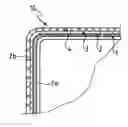
FIG. 1 is a sectional view of a first embodiment of the tank according to the present invention.
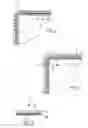
FIG. 2 is a sectional view of a second embodiment of a tank according to the present invention.
FIG. 3 is a sectional detailed view of part of the tank of FIG. 1, namely a liner.
DETAILED DESCRIPTION
FIG. 1 shows a mold 1 intended to produce a tank 10 according to the present invention.
In this first embodiment, the tank 10 is made as follows. A liner 2, having properties of sealing against the liquid, impermeability to the vapor of said fuel and dissipation of the electrostatic charges, is positioned on the outer wall 1b of the mold 1 having the shape of the tank to be manufactured. A reinforcing textile 4 is next assembled to the liner 2 using an intermediate layer 3, for example a coating layer of the textile reinforcement.
In the second embodiment illustrated by FIG. 2, a reinforcing textile 4 is positioned on the inner wall 1a of a mold 1 in the shape of the tank to be manufactured, then a liner 2 having properties of sealing against the liquid, impermeability to the vapor of said fuel, and dissipation of the electrostatic charges is assembled on the reinforcing textile 4 using an intermediate layer 3, for example a coating layer of the textile.
The assembly between the liner 2 and the intermediate layer may be of the hot or cold gluing, co-vulcanization or welding type.
The textile reinforcing layer 4 includes several thicknesses of textile reinforcements.
Once produced and stripped, the liner 2 of the tank 10 includes an inner face 2a intended to be in contact with the fuel.
The liner 2 has a total thickness smaller than 150 microns, which makes it possible to obtain a tank with a reduced mass.
It can be produced by film extrusion or extrusion blow molding or bi-extrusion or multi-extrusion, or by aqueous or solvent coating on an anti-adhesive substrate, or by a typical method for applying polymer paints through aqueous or solvent avenues, such as spraying, application by brush or by roller.
Advantageously, at its outer face 2b, the liner 2 has an impermeability with respect to the fuel vapors lower than 6 g/m2/24 h.
Likewise, the inner face 2a of the liner 2 has a surface resistivity lower than 108 ohm/square.
As shown in FIG. 3, the liner 2 can include two layers A and B, but it may also include only one layer or more than two layers, in particular an additional layer to provide the bond between layers A and B, or to provide the bond between layer A and the intermediate layer 3.
In the embodiment including two layers, the first outer layer A having properties of sealing against the liquid and impermeability to the fuel vapor has, as main component in its matrix, at least one polymer chosen from among polyamines such as Pa 6, Pa 6.6, Pa 11, Pa 12, Pa 6.12, Pa 4.6, co-polyamides, aromatic polyamides, polyimides, polyphenol sulfides, fluorinated polymers such as PVF, PVDF, ETFE or PFA, polyether ketones such as PEEK or PEKK, or EVOH, while the second inner layer B (the layer in contact with the fuel) having properties of dissipating electrostatic charges has, as main component in its matrix, at least one polymer chosen from among polyamines such as Pa 6, Pa 6.6, Pa 11, Pa 12, Pa 6.12, Pa 4.6, co-polyamides, aromatic polyamides, polyimides, polyphenol sulfides, fluorinated polymers such as PVF, PVDF, ETFE, FEP or PFA, polyether ketones such as PEEK or PEKK, EVOH, polyurethane, nitrile and its derivatives such as hydrogenated nitrile or nitrile/PVC, epichlorhydrin and its derivatives, fluoropolymer and its derivatives, polychloroprene or fluorosilicone.
In order to contribute the property of dissipating electrostatic charges, the liner 2 contains conducting fillers such as standard reinforcing carbon black, conducting carbon black, single-, double- or multi-walled carbon nanotubes, graphite, intrinsic conducting polymers or metal fillers, or a mixture of at least some of these fillers.
Advantageously, the quantity of conducting fillers in the liner 2 is sufficient to ensure the presence of an inner percolation network.
These conducting fillers are integrated within the matrix of the liner 2 by mixing in a single or twin screw extruder, by mixing through a liquid avenue, the matrix being dissolved in a solvent, or an aqueous avenue, or by mixing of the rubber type for elastomer matrices on a bi-cylinder mixer or in an internal mixer. The mixing method for these fillers within the matrix will affect their distribution (homogeneity of concentration, dispersion) and their orientation. It will therefore also influence the proportion of fillers to be introduced to obtain a percolation.
The liner 2 includes conducting fillers at rates of 0.5 to 100 parts per 100 parts polymer.
In the case where the conducting fillers are of the carbon nanotube type, the latter are present in a quantity lower than 10 parts per 100 parts polymer, preferably lower than 7 parts per 100 parts polymer, and more advantageously lower than 5 parts per 100 parts polymer.
Adding an excessive quantity of conducting fillers within the matrix may lead to a weakening of the barrier properties that is incompatible with the invention in the case of a single-layer liner.
The fillers of the intrinsic conductor polymer type (polyaniline, for example) allow little or no deterioration of the barrier properties.
Using lamellar conducting fillers of the graphite type, which may or may not be associated with the other types of fillers, may prove particularly useful to retain good barrier properties. The lamellar fillers create a more twisting conveyance circuit for the fuel within the matrix that may counterbalance the weakening of the barrier properties.
If the conducting fillers are of the carbon black type, their specific surface per BET according to standard ASTM D3037 is comprised between 12 and 2000 m2/g.
Of course, the detailed description of the subject matter of the Invention, provided solely as an illustration, in no way constitutes a limitation, technical equivalents also being comprised in the scope of the present invention.
Claims
What is claimed is:1. A flexible fuel tank (10) comprising, from the inside to the outside of said tank:
a single-layer or multilayer liner (2) having properties of sealing with respect to the liquid, impermeability to the vapor of said fuel, and dissipation of electrostatic charges, said liner (2) including an inner face (2a) intended to be in contact with the fuel and an outer face (2b);
an intermediate layer (3) in contact with the outer face (2b) of the liner (2);
a textile reinforcing layer (4) in contact with the intermediate layer (3).
2. The tank (10) of claim 1, wherein the liner (2) has at its outer face (2b) an impermeability with respect to the fuel vapors below 6 g/m2/24 h.
3. The tank (10) of claim 1, wherein the inner face (2a) of the liner (2) has a surface resistivity lower than 108 ohm/square.
4. The tank (10) of claim 1, wherein the liner (2) comprises at least:
a first outer layer (A) having said properties of sealing with respect to the liquid and impermeability to the fuel vapor and having, as main component in its matrix, at least one polymer chosen from among polyamides such as Pa 6, Pa 6.6, Pa 11, Pa 12, Pa 6.12, Pa 4.6, co-polyamides, aromatic polyamides, polyimides, polyphenol sulfites, fluorinated polymers such as PVF, PVDF, ETFE or PFA, polyether ketones such as PEEK or PEKK, or EVOH; and
a second inner layer (B) having the properties of dissipating electrostatic charges and having, as primary component in its matrix, at least one polymer chosen from among polyamides such as Pa 6, Pa 6.6, Pa 11, Pa 12, Pa 6.12, Pa 4.6, co-polyamides, aromatic polyamides, polyimides, polyphenol sulfides, fluorinated polymers such as PVF, PVDF, ETFE, FEP or PFA, polyether ketones such as PEEK or PEKK, EVOH, polyurethane, nitrile and its derivatives such as hydrogenated nitrile or nitrile/PVC, epichlorhydrin and its derivatives, fluoropolymer and its derivatives, polychloroprene or fluorosilicone.
5. The tank (10) of claim 4, wherein the liner (2) includes fillers of the carbon nanotube type in a quantity lower than 10 parts per 100 parts polymer.
6. The tank (10) of claim 1, wherein the liner (2) contains conducting fillers such as standard reinforcing carbon black, conducting carbon black, single-, double- or multi-walled carbon nanotubes, graphite, intrinsic conducting polymers or metal fillers, or a mixture of at least some of these fillers.
7. The tank (10) of claim 6, wherein the conducting fillers are integrated within the matrix of the liner (2) by mixing in a single or twin screw extruder, by mixing through a liquid avenue or by mixing of the rubber on two-cylinder mixer type or in an internal mixer.
8. The tank (10) of claim 6, wherein the liner (2) includes conducting fillers at rates from 0.5 to 100 parts per 100 parts polymer.
9. The tank (10) of claim 6, wherein the liner (2) includes fillers of the carbon black type, the specific surface of which per BET according to standard ASTM D3037 is comprised between 12 and 2000 m2/g.
10. The tank (10) of claim 6, wherein the quantity of conducting fillers in the liner (2) is sufficient to ensure the presence of an internal percolation network.
11. The tank (10) of claim 1, wherein the liner (2) has a total thickness smaller than 150 microns.
12. The tank (10) of claim 1, wherein the liner (2) is manufactured by a film extrusion or extrusion blow molding or bi-extrusion or multi-extrusion.
13. The tank (10) of claim 1, wherein the liner (2) is manufactured by aqueous coating or solvent on an anti-adhesive substrate.
14. The tank (10) of claim 1, wherein the liner (2) is manufactured using an application method for polymer paints in an aqueous or solvent route, selected from spraying, application by brush or roller.
15. The tank (10) of claim 1, wherein the reinforcing textile layer (4) includes several thicknesses of textile reinforcements.
16. The tank (10) of claim 1, wherein the liner (2) is bonded to the textile reinforcement (4) by hot gluing, cold gluing, co-vulcanization or welding.
17. A method for producing a flexible fuel tank (10) comprising:
positioning, on an outer wall of a mold in a shape of the tank to be manufactured, a liner (2) having properties of sealing against the liquid, impermeability to the vapor of said fuel, dissipation of electrostatic charges, said liner (2) including an inner face (2a) intended to be in contact with the fuel,
assembling a reinforcing textile (4) on the liner (2) using an intermediate layer (3).
18. A method for producing a flexible fuel tank (10) comprising:
positioning a reinforcing textile (4) on an inner wall of a mold in a shape of the tank to be manufactured,
assembling on the reinforcing textile (4), using an intermediate layer (3), a liner (2) having properties of sealing against the liquid, impermeability to the vapor of said fuel, dissipation of the electrostatic charges, said liner (2) including an inner face (2a) intended to be in contact with the fuel.
Images & Drawings included:
Sources:
- United States Patent and Trademark Office - verify current appl. status at the USPTO↗
Recent applications in this class:
- » 20250171158 2025-05-29
Collapsible Fuel Cells for Aircraft - » 20250128823 2025-04-24
IMPROVEMENTS RELATING TO FUEL STRINGER DUCT BULKHEADS - » 20250066033 2025-02-27
ASSEMBLY FOR A TANK - » 20240417098 2024-12-19
SYSTEM AND METHOD OF CONTROLLING THE DEFLECTIONS OF A PRESSURE TANK MOUNTED WITHIN A VACUUM TANK - » 20240417097 2024-12-19
Structurally integrated vacuum tank and method of using the same - » 20240359808 2024-10-31
TANK WITH AT LEAST ONE ANTI-SLOSHING WALL ARRANGEMENT, AND AIRCRAFT WITH SUCH TANK - » 20240336368 2024-10-10
Collapsible fuel cells for aircraft - » 20240262526 2024-08-08
SYSTEMS AND METHODS FOR A LIQUIFIED GAS FUEL TANK INCORPORATED INTO AN AIRCRAFT - » 20240246691 2024-07-25
AIRCRAFT COMPRISING A FUEL TANK - » 20240003298 2024-01-04
Adaptor for a fuel system of an aircraft engine