Vehicle system and method for activating hazard lights during battery disconnect events
US20170328959A1
2017-11-16
15/668,758
2017-08-04
✅ Patent granted
US 10,620,271 B2
2020-04-14
-
-
Behrang Badii
David B. Kelley | Carlson, Gaskey & Olds
2038-02-20
Abstract:
A vehicle system includes a high voltage battery and at least one control module configured to monitor the high voltage battery and command a visual warning in response to a disconnect event of the high voltage battery. The visual warning may be produced by a hazard light.
Inventors:
- Robert Bolduc 4 🇺🇸 Allen Park, MI, United States
- Ken Jon Cunningham 2 🇺🇸 Livonia, MI, United States
- Massahiro Kimoto 1 🇺🇸 Plymouth, MI, United States
Assignee:
- FORD GLOBAL TECHNOLOGIES, LLC 23,240 🇺🇸 Dearborn, MI, United States
Applicant:
Interested in similar patents?
Get notified when new applications in this technology area are published.
Classification:
G01R31/36 IPC
Arrangements for testing electric properties; Arrangements for locating electric faults; Arrangements for electrical testing characterised by what is being tested not provided for elsewhere Arrangements for testing, measuring or monitoring the electrical condition of accumulators or electric batteries, e.g. capacity or state of charge [SoC]
B60L2250/10 » CPC further
Driver interactions by alarm
B60L2250/16 » CPC further
Driver interactions by display
B60Q1/46 » CPC further
Arrangement of optical signalling or lighting devices, the mounting or supporting thereof or circuits therefor the devices being primarily intended to indicate the vehicle, or parts thereof, or to give signals, to other traffic for giving flashing caution signals during drive, other than signalling change of direction, e.g. flashing the headlights or hazard lights
G01R31/371 » CPC main
Arrangements for testing electric properties; Arrangements for locating electric faults; Arrangements for electrical testing characterised by what is being tested not provided for elsewhere; Arrangements for testing, measuring or monitoring the electrical condition of accumulators or electric batteries, e.g. capacity or state of charge [SoC] with remote indication, e.g. on external chargers
B60L3/0046 » CPC further
Electric devices on electrically-propelled vehicles for safety purposes; Monitoring operating variables, e.g. speed, deceleration or energy consumption; Detecting, eliminating, remedying or compensating for drive train abnormalities, e.g. failures within the drive train relating to electric energy storage systems, e.g. batteries or capacitors
B60L3/04 » CPC further
Electric devices on electrically-propelled vehicles for safety purposes; Monitoring operating variables, e.g. speed, deceleration or energy consumption Cutting off the power supply under fault conditions
B60L58/12 » CPC further
Methods or circuit arrangements for monitoring or controlling batteries or fuel cells, specially adapted for electric vehicles for monitoring or controlling batteries responding to state of charge [SoC]
B60Q1/50 » CPC further
Arrangement of optical signalling or lighting devices, the mounting or supporting thereof or circuits therefor the devices being primarily intended to indicate the vehicle, or parts thereof, or to give signals, to other traffic for indicating other intentions or conditions, e.g. request for waiting or overtaking
B60C23/02 » CPC further
Devices for measuring, signalling, controlling, or distributing tyre pressure or temperature, specially adapted for mounting on vehicles; Arrangement of tyre inflating devices on vehicles, e.g. of pumps or of tanks; Tyre cooling arrangements Signalling devices actuated by tyre pressure
B60C23/04 » CPC further
Devices for measuring, signalling, controlling, or distributing tyre pressure or temperature, specially adapted for mounting on vehicles; Arrangement of tyre inflating devices on vehicles, e.g. of pumps or of tanks; Tyre cooling arrangements; Signalling devices actuated by tyre pressure mounted on the wheel or tyre
B60C23/0416 » CPC further
Devices for measuring, signalling, controlling, or distributing tyre pressure or temperature, specially adapted for mounting on vehicles; Arrangement of tyre inflating devices on vehicles, e.g. of pumps or of tanks; Tyre cooling arrangements; Signalling devices actuated by tyre pressure mounted on the wheel or tyre transmitting the signals by non-mechanical means from the wheel or tyre to a vehicle body mounted receiver; Automatically identifying wheel mounted units, e.g. after replacement or exchange of wheels allocating a corresponding wheel position on vehicle, e.g. front/left or rear/right
B60K28/14 » CPC further
Safety devices for propulsion-unit control, specially adapted for, or arranged in, vehicles, e.g. preventing fuel supply or ignition in the event of potentially dangerous conditions responsive to conditions relating to the vehicle responsive to accident or emergency, e.g. deceleration, tilt of vehicle
B60L7/00 » CPC further
Electrodynamic brake systems for vehicles in general
B60L7/10 » CPC further
Electrodynamic brake systems for vehicles in general Dynamic electric regenerative braking
B60L7/26 » CPC further
Electrodynamic brake systems for vehicles in general with additional mechanical or electromagnetic braking Controlling the braking effect
B60L7/28 » CPC further
Electrodynamic brake systems for vehicles in general Eddy-current braking
B60L15/10 » CPC further
Methods, circuits, or devices for controlling the traction-motor speed of electrically-propelled vehicles for automatic control superimposed on human control to limit the acceleration of the vehicle, e.g. to prevent excessive motor current
B60L2240/12 » CPC further
Control parameters of input or output; Target parameters; Vehicle control parameters Speed
B60R16/00 » CPC further
Electric or fluid circuits specially adapted for vehicles and not otherwise provided for; Arrangement of elements of electric or fluid circuits specially adapted for vehicles and not otherwise provided for
B60R21/013 » CPC further
Arrangements or fittings on vehicles for protecting or preventing injuries to occupants or pedestrians in case of accidents or other traffic risks; Electrical circuits for triggering safety arrangements, in case of vehicle accidents or impending vehicle accidents including means for detecting collisions, impending collisions or roll-over
B60T1/005 » CPC further
Arrangements of braking elements, i.e. of those parts where braking effect occurs specially for vehicles by locking of wheel or transmission rotation
B60T7/12 » CPC further
Brake-action initiating means for automatic initiation; for initiation not subject to will of driver or passenger
B60T7/22 » CPC further
Brake-action initiating means for automatic initiation; for initiation not subject to will of driver or passenger initiated by contact of vehicle, e.g. bumper, with an external object, e.g. another vehicle, or by means of contactless obstacle detectors mounted on the vehicle
B60T8/17 » CPC further
Arrangements for adjusting wheel-braking force to meet varying vehicular or ground-surface conditions, e.g. limiting or varying distribution of braking force Using electrical or electronic regulation means to control braking
B60T8/885 » CPC further
Arrangements for adjusting wheel-braking force to meet varying vehicular or ground-surface conditions, e.g. limiting or varying distribution of braking force responsive to a speed condition, e.g. acceleration or deceleration with failure responsive means, i.e. means for detecting and indicating faulty operation of the speed responsive control means using electrical circuitry
B60W10/04 » CPC further
Conjoint control of vehicle sub-units of different type or different function including control of propulsion units
B60W10/108 » CPC further
Conjoint control of vehicle sub-units of different type or different function including control of change-speed gearings; Infinitely variable gearings Friction gearings
B60W2510/244 » CPC further
Input parameters relating to a particular sub-units; Energy storage means for electrical energy Charge state
F16H9/04 » CPC further
Gearings for conveying rotary motion with variable gear ratio, or for reversing rotary motion, by endless flexible members without members having orbital motion using belts, V-belts, or ropes
F16H61/66 » CPC further
Control functions within change-speed- or reversing-gearings for conveying rotary motion specially adapted for continuously variable gearings
G05D3/00 » CPC further
Control of position or direction
G06F17/00 » CPC further
Digital computing or data processing equipment or methods, specially adapted for specific functions
G06G7/78 » CPC further
Devices in which the computing operation is performed by varying electric or magnetic quantities; Analogue computers for specific processes, systems or devices, e.g. simulators for direction-finding, locating, distance or velocity measuring, or navigation systems
H01Q1/3233 » CPC further
Details of, or arrangements associated with, antennas; Adaptation for use in or on movable bodies; Adaptation for use in or on road or rail vehicles characterised by the application wherein the antenna is used particular used as part of a sensor or in a security system, e.g. for automotive radar, navigation systems
B60L3/00 IPC
Electric devices on electrically-propelled vehicles for safety purposes; Monitoring operating variables, e.g. speed, deceleration or energy consumption
B60T1/00 IPC
Arrangements of braking elements, i.e. of those parts where braking effect occurs specially for vehicles
B60T8/88 IPC
Arrangements for adjusting wheel-braking force to meet varying vehicular or ground-surface conditions, e.g. limiting or varying distribution of braking force responsive to a speed condition, e.g. acceleration or deceleration with failure responsive means, i.e. means for detecting and indicating faulty operation of the speed responsive control means
H01Q1/32 IPC
Details of, or arrangements associated with, antennas; Adaptation for use in or on movable bodies Adaptation for use in or on road or rail vehicles
Description
CROSS REFERENCE TO RELATED APPLICATIONS
This is a divisional of U.S. patent application Ser. No. 14/714,583, which was filed on May 18, 2015.
TECHNICAL FIELD
This disclosure relates to a vehicle system and method for an electrified vehicle. The vehicle system is configured to activate one or more hazard lights of the electrified vehicle in response to high voltage battery disconnect events.
BACKGROUND
The need to reduce fuel consumption and emissions in vehicles is well known. Therefore, vehicles are being developed that reduce or completely eliminate reliance on internal combustion engines. Electrified vehicles are one type of vehicle currently being developed for this purpose. In general, electrified vehicles differ from conventional motor vehicles because they are selectively driven by one or more battery powered electric machines. Conventional motor vehicles, by contrast, rely exclusively on an internal combustion engine to drive the vehicle.
Electrified vehicle powertrains are typically equipped with a high voltage battery having a plurality of battery cells that store electrical power for powering the electric machines and other electric loads. During certain vehicle fault conditions, the high voltage battery may be intentionally disconnected from the vehicle's high voltage electrical bus, thereby resulting in the loss of vehicle motive power.
SUMMARY
A method according to an exemplary aspect of the present disclosure includes, among other things, activating hazard lights of an electrified vehicle in response to a high voltage battery disconnect event.
In a further non-limiting embodiment of the foregoing method, the activating step is performed if a speed of the electrified vehicle exceeds a predefined speed threshold.
In a further non-limiting embodiment of either of the foregoing methods, the activating step is performed if a power request from an operator of the electrified vehicle exceeds a predefined power request threshold.
In a further non-limiting embodiment of any of the foregoing methods, the activating step is performed if a speed of the electrified vehicle exceeds a predefined speed threshold and a power request from an operator of the electrified vehicle exceeds a predefined power request threshold.
In a further non-limiting embodiment of any of the foregoing methods, the high voltage battery disconnect event indicates that the electrified vehicle has lost motive power.
In a further non-limiting embodiment of any of the foregoing methods, the activating step includes automatically flashing the hazard lights without a specific request from a vehicle operator.
In a further non-limiting embodiment of any of the foregoing methods, the method includes automatically flashing the hazard lights in a first flashing pattern in response to the high voltage battery disconnect event and flashing the hazard lights in a second, different flashing pattern in response to a specific request from a vehicle operator.
In a further non-limiting embodiment of any of the foregoing methods, the method includes, prior to the activating step, monitoring a high voltage battery of the electrified vehicle for fault conditions.
In a further non-limiting embodiment of any of the foregoing methods, the method includes disconnecting the high voltage battery from a high voltage bus to cause the high voltage battery disconnect event.
In a further non-limiting embodiment of any of the foregoing methods, the activating step includes flashing the hazard lights to provide a visual warning to a vehicle nearby the electrified vehicle if one or more additional vehicle conditions have been met in addition to the high voltage battery disconnect event.
A vehicle system according to another exemplary aspect of the present disclosure includes, among other things, a high voltage battery and at least one control module configured to monitor the high voltage battery and command a visual warning in response to a disconnect event of the high voltage battery.
In a further non-limiting embodiment of the foregoing vehicle system, the at least one control module includes a first control module and a second control module in communication with the first control module.
In a further non-limiting embodiment of either of the foregoing vehicle systems, the first control module is configured to monitor the high voltage battery and the second control module is configured to command the visual warning.
In a further non-limiting embodiment of any of the foregoing vehicle system, the first control module and the second control module communicate over a communication link.
In a further non-limiting embodiment of any of the foregoing vehicle systems, a hazard light is configured to provide the visual warning.
In a further non-limiting embodiment of any of the foregoing vehicle systems, a low voltage battery is configured to power the hazard light during the disconnect event.
In a further non-limiting embodiment of any of the foregoing vehicle systems, a switch is movable between an open position in which the low voltage battery is decoupled from the hazard light and a closed position in which the low voltage battery is coupled to the hazard light during the disconnect event.
In a further non-limiting embodiment of any of the foregoing vehicle systems, at least one contactor is configured to selectively disconnect the high voltage battery from a high voltage load to create the disconnect event.
The embodiments, examples and alternatives of the preceding paragraphs, the claims, or the following description and drawings, including any of their various aspects or respective individual features, may be taken independently or in any combination. Features described in connection with one embodiment are applicable to all embodiments, unless such features are incompatible.
The various features and advantages of this disclosure will become apparent to those skilled in the art from the following detailed description. The drawings that accompany the detailed description can be briefly described as follows.
BRIEF DESCRIPTION OF THE DRAWINGS
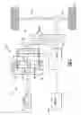
FIG. 1 schematically illustrates a powertrain of an electrified vehicle.
FIG. 2 schematically illustrates a vehicle system of an electrified vehicle.
FIG. 3 schematically illustrates a control strategy for providing a visual warning that an electrified vehicle has lost motive power.
DETAILED DESCRIPTION
This disclosure describes a vehicle system and method for controlling an electrified vehicle. In some embodiments, the hazard lights of the electrified vehicle are activated in response to a high voltage battery disconnect event. The high voltage battery disconnect event may indicate that the electrified vehicle has lost motive power. Flashing the hazard lights provides a visual warning to drivers of nearby vehicles of such a loss of motive power. In some embodiments, the hazard lights are activated in response to a high voltage battery disconnect event if certain additional vehicle conditions are met. These and other features are discussed in greater detail in the following paragraphs of this detailed description.
FIG. 1 schematically illustrates a powertrain 10 for an electrified vehicle 12. Although depicted as a hybrid electric vehicle (HEV), it should be understood that the concepts described herein are not limited to HEV's and could extend to other electrified vehicles, including, but not limited to, plug-in hybrid electric vehicles (PHEV's), battery electric vehicles (BEV's) and fuel cell vehicles.
In one embodiment, the powertrain 10 is a power-split powertrain system that employs a first drive system and a second drive system. The first drive system includes a combination of an engine 14 and a generator 18 (i.e., a first electric machine). The second drive system includes at least a motor 22 (i.e., a second electric machine), the generator 18, and a battery 24. In this example, the second drive system is considered an electric drive system of the powertrain 10. The first and second drive systems generate torque to drive one or more sets of vehicle drive wheels 28 of the electrified vehicle 12. Although a power-split configuration is shown, this disclosure extends to any hybrid or electric vehicle including full hybrids, parallel hybrids, series hybrids, mild hybrids or micro hybrids.
The engine 14, which in one embodiment is an internal combustion engine, and the generator 18 may be connected through a power transfer unit 30, such as a planetary gear set. Of course, other types of power transfer units, including other gear sets and transmissions, may be used to connect the engine 14 to the generator 18. In one non-limiting embodiment, the power transfer unit 30 is a planetary gear set that includes a ring gear 32, a sun gear 34, and a carrier assembly 36.
The generator 18 can be driven by the engine 14 through the power transfer unit 30 to convert kinetic energy to electrical energy. The generator 18 can alternatively function as a motor to convert electrical energy into kinetic energy, thereby outputting torque to a shaft 38 connected to the power transfer unit 30. Because the generator 18 is operatively connected to the engine 14, the speed of the engine 14 can be controlled by the generator 18.
The ring gear 32 of the power transfer unit 30 may be connected to a shaft 40, which is connected to vehicle drive wheels 28 through a second power transfer unit 44. The second power transfer unit 44 may include a gear set having a plurality of gears 46. Other power transfer units may also be suitable. The gears 46 transfer torque from the engine 14 to a differential 48 to ultimately provide traction to the vehicle drive wheels 28. The differential 48 may include a plurality of gears that enable the transfer of torque to the vehicle drive wheels 28. In one embodiment, the second power transfer unit 44 is mechanically coupled to an axle 50 through the differential 48 to distribute torque to the vehicle drive wheels 28.
The motor 22 can also be employed to drive the vehicle drive wheels 28 by outputting torque to a shaft 52 that is also connected to the second power transfer unit 44. In one embodiment, the motor 22 and the generator 18 cooperate as part of a regenerative braking system in which both the motor 22 and the generator 18 can be employed as motors to output torque. For example, the motor 22 and the generator 18 can each output electrical power to the battery 24.
The battery 24 is an exemplary electrified vehicle battery. The battery 24 may be configured as a high voltage traction battery pack that includes a plurality of battery cells capable of outputting electrical power to operate the motor 22 and the generator 18, among other components. Other types of energy storage devices and/or output devices can also be used to electrically power the electrified vehicle 12.
In one non-limiting embodiment, the electrified vehicle 12 has two basic operating modes. The electrified vehicle 12 may operate in an Electric Vehicle (EV) mode where the motor 22 is used (generally without assistance from the engine 14) for vehicle propulsion, thereby depleting the battery 24 state of charge up to its maximum allowable discharging rate under certain driving patterns/cycles. The EV mode is an example of a charge depleting mode of operation for the electrified vehicle 12. During EV mode, the state of charge of the battery 24 may increase in some circumstances, for example due to a period of regenerative braking. The engine 14 is generally OFF under a default EV mode but could be operated as necessary based on a vehicle system state or as permitted by the operator.
The electrified vehicle 12 may additionally operate in a Hybrid (HEV) mode in which the engine 14 and the motor 22 are both used for vehicle propulsion. The HEV mode is an example of a charge sustaining mode of operation for the electrified vehicle 12. During the HEV mode, the electrified vehicle 12 may reduce the motor 22 propulsion usage in order to maintain the state of charge of the battery 24 at a constant or approximately constant level by increasing the engine 14 propulsion. The electrified vehicle 12 may be operated in other operating modes in addition to the EV and HEV modes within the scope of this disclosure.
FIG. 2 is a highly schematic depiction of a vehicle system 56 that may be incorporated into a vehicle, such as the electrified vehicle 12 of FIG. 1. The vehicle system 56 is adapted to activate one or more hazard lights 58 of the electrified vehicle 12 when the electrified vehicle loses motive power. Stated another way, the vehicle system 56 is designed to automatically provide a visual warning to drivers of nearby vehicles, by flashing the hazard lights 58, in response to high voltage battery disconnect events that result in the electrified vehicle losing motive power.
In one non-limiting embodiment, the exemplary vehicle system 56 includes a high voltage battery 60, a high voltage load 62, a low voltage battery 64, hazard lights 58, a first control module 66 and a second control module 68. These and additional components of the vehicle system 56 are described below.
The high voltage battery 60 may include a plurality of battery cells, capacitors, or other energy storage devices that are interconnected relative to one another to form the high voltage battery 60. The energy storage devices of the high voltage battery 60 store electrical energy that may be supplied to power various loads residing onboard an electrified vehicle. In a non-limiting embodiment, the high voltage battery 60 is capable of producing at least 100 volts of electricity. The high voltage battery 60 may supply this electrical power to the high voltage load 62 for providing motive power to the electrified vehicle. In a non-limiting embodiment, the high voltage load 62 is an electric machine such as an electric motor, a generator, or a combined motor/generator.
One or more contactors 72 may be employed to selectively open and close a connection between the high voltage battery 60 and the high voltage load 62. In one embodiment, the contactors 72 act as high voltage relays for electronically switching a supply current to the high voltage load 62. For example, the contactors 72 may couple or decouple the high voltage power generated in the high voltage battery 60 to or from the high voltage load 62. When in closed positions (shown in phantom lines), the contractors 72 couple the high voltage battery 60 to the high voltage load 62 over a high voltage bus 74. Alternatively, when the contactors 72 are in open positions, the high voltage battery 60 is decoupled or disconnected from the high voltage load 62.
The low voltage battery 64 may supply electrical power to various low voltage electrical loads (e.g., lighting systems, logic circuitry, etc.) of the electrified vehicle. For example, the low voltage battery 64 may power the hazard lights 58. In a non-limiting embodiment, the low voltage battery 64 is a 12V battery. The low voltage battery 64 may be selectively connected to and disconnected from the hazard lights 58 using a switch 70.
The first control module 66 and the second control module 68 may be part of an overall vehicle control unit, such as a vehicle system controller (VSC) or could alternatively be stand-alone control units separate from the VSC. In one embodiment, the first control module 66 and the second control module 68 include executable instructions for interfacing with and commanding operation of various components of the vehicle system 56. The first control module 66 and the second control module 68 may both include multiple inputs and outputs for interfacing with the various components, and may include processing units and non-transitory memory for executing the various control strategies and modes of the vehicle system 56.
In a non-limiting embodiment, the first control module 66 controls operation of at least the high voltage battery 60 and the contactors 72 of the vehicle system 56. For example, the first control module 66 may monitor temperatures of the battery cells of the high voltage battery 60, may monitor and control the state of charge (SOC) of the high voltage battery 60, may control charging and discharging operations of the battery cells of the high voltage battery 60, and may control opening and closing of the contactors 72. These are but non-limiting examples of the many potential functions of the first control module 66 of the vehicle system 56.
In another embodiment, the second control module 68 controls operation of at least the low voltage battery 64 and the switch 70 for activating the hazard lights 58 of the vehicle system 56. For example, in a non-limiting embodiment, the second control module 68 may command the switch 70 closed (shown in phantom lines) to activate the hazard lights 58 using power from the low voltage battery 64. The second control module 68 may include many other functions in addition to these functions.
The first control module 66 and the second control module 68 may communicate with one another over a communication link 76. In one non-limiting embodiment, the communication link 76 is a controller area network designed to allow the first control module 66 and the second control module 68 to communicate with one another and with other control modules.
During certain fault conditions, such as battery cell overcharge and/or battery cell over-discharging conditions, the first control module 66 may command the contactors 72 open to disconnect the high voltage battery 60 from the high voltage bus 74, and thus, disconnect the high voltage battery 60 from the high voltage load 62. This is referred to as a “high voltage battery disconnect event” and results in the electrified vehicle losing motive power. The first control module 66 may communicate a signal over the communication link 76 to the second control module 68 in response to detecting a high voltage battery disconnect event. In response, the second control module 68 may command the switch 70 closed to activate the hazard lights 58. In this way, the vehicle system 56 provides a visual warning to other vehicle drivers that motive power has been lost.
FIG. 3, with continued reference to FIGS. 1-2, schematically illustrates an exemplary control strategy 100 for controlling the vehicle system 56. For example, the control strategy 100 can be performed to provide a visual warning to other vehicle drivers by flashing the hazard lights 58 in response to high voltage battery disconnect events. The first control module 66 and the second control module 68 can be programmed with one or more algorithms adapted to execute the control strategy 100, or any other control strategy. In one non-limiting embodiment, the control strategy 100 may be stored as executable instructions in non-transitory memory of the first control module 66 and the second control module 68.
As shown in FIG. 3, the control strategy 100 begins at block 102. At block 104, the control strategy 100 monitors the high voltage battery 60 for battery fault conditions. The battery fault conditions may include, among other conditions, battery cell overcharging and/or battery cell over-discharging conditions. The first control module 66 may continuously monitor the high voltage battery 60 for such faults.
Next, at block 106, the control strategy 100 determines whether a battery fault condition has been detected. If “NO,” the first control module 66 continues to monitor the high voltage battery 60. If “Yes,” however, the control strategy 100 proceeds to block 108.
At block 108, the high voltage battery 60 is disconnected from the high voltage load 62. In a non-limiting embodiment, the first control module 66 commands the contactors 72 open to disconnect the high voltage battery 60 from the high voltage load 62. Opening the contactors 72 renders a high voltage battery disconnect event which causes the electrified vehicle 12 to lose motive power.
The control strategy 100 next determines whether one or more additional vehicle conditions exist for deciding whether to provide a visual warning to other drivers that the electrified vehicle 12 has lost motive power. This is schematically shown at block 110 of the control strategy 100. In a first embodiment, the control strategy 100 determines if a speed of the electrified vehicle 12 exceeds a predefined speed threshold. The predefined speed threshold is a calibratable value that may be set at any vehicle speed. In a second embodiment, the control strategy 100 determines if a power request from the operator of the electrified vehicle 12 exceeds a predefined power request threshold. The predefined power request threshold is a calibratable value that may be derived from an accelerator pedal position. In yet another embodiment, the control strategy 100 determines whether the speed of the electrified vehicle 12 exceeds a predefined speed threshold and whether a power request exceeds a predefined power request threshold. Other vehicle conditions may also be monitored for determining whether to issue the visual warning.
If the analysis at block 110 results in an answer of “NO,” the control strategy ends at block 112 and no visual warning is activated. Alternatively, if the answer to block 110 is “YES,” the control strategy 100 proceeds to block 114 by activating the hazard lights 58 in order to provide the visual warning of loss of motive power to other vehicle operators. The first control module 66 may communicate a signal to the second control module 68 to activate the hazard lights 58. In response to receiving this signal, the second control module 68 may command the switch 70 closed to activate the hazard lights 58 by using power from the low voltage battery 64.
Once activated, the hazard lights 58 may flash in a predefined flashing pattern to provide the visual warning to vehicles that may be nearby the electrified vehicle 12. In a non-limiting embodiment, the predefined flashing pattern used to automatically indicate a loss of motive power is a different flashing pattern than is used if the vehicle operator of the electrified vehicle 12 has specifically requested operation of the hazard lights 58, such as by depressing a button within the vehicle cabin of the electrified vehicle 12. For example, the predefined flashing pattern used to automatically indicate loss of motive power may flash the hazard lights 58 more rapidly than other flashing patterns to draw quicker attention to the electrified vehicle 12.
Although the different non-limiting embodiments are illustrated as having specific components or steps, the embodiments of this disclosure are not limited to those particular combinations. It is possible to use some of the components or features from any of the non-limiting embodiments in combination with features or components from any of the other non-limiting embodiments.
It should be understood that like reference numerals identify corresponding or similar elements throughout the several drawings. It should be understood that although a particular component arrangement is disclosed and illustrated in these exemplary embodiments, other arrangements could also benefit from the teachings of this disclosure.
The foregoing description shall be interpreted as illustrative and not in any limiting sense. A worker of ordinary skill in the art would understand that certain modifications could come within the scope of this disclosure. For these reasons, the following claims should be studied to determine the true scope and content of this disclosure.
Claims
What is claimed is:1. A vehicle system, comprising:
a high voltage battery; and
at least one control module configured to monitor the high voltage battery and command a visual warning in response to a disconnect event of the high voltage battery.
2. The vehicle system as recited in claim 1, wherein the at least one control module includes a first control module and a second control module in communication with the first control module.
3. The vehicle system as recited in claim 2, wherein the first control module is configured to monitor the high voltage battery and the second control module is configured to command the visual warning.
4. The vehicle system as recited in claim 2, wherein the first control module and the second control module communicate over a communication link.
5. The vehicle system as recited in claim 1, comprising a hazard light configured to provide the visual warning.
6. The vehicle system as recited in claim 5, comprising a low voltage battery configured to power the hazard light during the disconnect event.
7. The vehicle system as recited in claim 6, comprising a switch that is movable between an open position in which the low voltage battery is decoupled from the hazard light and a closed position in which the low voltage battery is coupled to the hazard light during the disconnect event.
8. The vehicle system as recited in claim 1, comprising at least one contactor configured to selectively disconnect the high voltage battery from a high voltage load to create the disconnect event.
9. The vehicle system as recited in claim 8, wherein the high voltage load is an electric motor, a generator, or a combined motor/generator.
10. The vehicle system as recited in claim 1, wherein the visual warning is provided to alert vehicles nearby a vehicle equipped with the vehicle system of the disconnect event.
11. A vehicle system, comprising:
a hazard light configured to provide a visual warning;
a high voltage battery; and
a vehicle control unit configured to monitor the high voltage battery and command the hazard light to produce a flashing light in response to a disconnect event of the high voltage battery, wherein the disconnect even indicates a loss of motive power.
12. The vehicle system as recited in claim 11, comprising a low voltage battery configured to power the hazard light during the disconnect event.
13. The vehicle system as recited in claim 12, comprising a switch that is movable between an open position in which the low voltage battery is decoupled from the hazard light and a closed position in which the low voltage battery is coupled to the hazard light during the disconnect event.
14. The vehicle system as recited in claim 11, comprising an electric motor or generator powered by the high voltage battery.
15. The vehicle system as recited in claim 14, comprising a contactor configured to selectively disconnect the high voltage battery from the electric motor or generator to create the disconnect event.
16. The vehicle system as recited in claim 11, wherein the vehicle control unit includes a first control module configured to monitor the high voltage battery and a second control module configured to control the hazard light.
17. The vehicle system as recited in claim 11, wherein the flashing light provides a visual warning of the disconnect event to vehicles nearby a vehicle equipped with the vehicle system.
Images & Drawings included:


Sources:
- United States Patent and Trademark Office - verify current appl. status at the USPTO↗
Similar patent applications:
Recent applications in this class:
- » 20190257888 2019-08-22
MANAGING BATTERY CONSUMPTION OF A TELEMATICS CONTROL UNIT - » 20190128970 2019-05-02
Battery measurement device and battery monitoring system - » 20190056457 2019-02-21
Fault detection for battery management systems - » 20190033395 2019-01-31
Systems and methods for monitoring and presenting battery information - » 20190033394 2019-01-31
Battery with internal monitoring system - » 20190033393 2019-01-31
ENERGY STORAGE DEVICE, SYSTEMS AND METHODS FOR MONITORING AND PERFORMING DIAGNOSTICS ON BATTERIES - » 20180299512 2018-10-18
Compact apparatus and system for a battery tester - » 20180188332 2018-07-05
Reporting of vehicle battery state of health and charge - » 20180120386 2018-05-03
Reusable battery indicator with electrical lock and key - » 20180011148 2018-01-11
Battery test report system and method
Recent applications for this Assignee:
- » 20250293257 2025-09-18
LITHIUM-ION BATTERY COMPONENT WITH POLAR BINDER - » 20250289391 2025-09-18
MANIFOLD TO SELECTIVELY INFLATE SEAT AIRBAGS - » 20250289296 2025-09-18
SUN VISOR FOR A MOTOR VEHICLE - » 20250285043 2025-09-11
REFACTORING INPUT STRINGS - » 20250282426 2025-09-11
VEHICLE STRUCTURAL ASSEMBLY HAVING STRUT CAPS - » 20250282423 2025-09-11
STRUCTURAL ASSEMBLY HAVING POCKETS - » 20250282315 2025-09-11
RETRACTABLE BUMPER ASSEMBLY WITH LOCK - » 20250282220 2025-09-11
VEHICLE DISPLAY CONTROL - » 20250278084 2025-09-04
SYSTEMS AND METHODS FOR ENABLING VEHICLE MOVEMENT VIA FORCE APPLIED TO AN EXTERNAL INTERFACE - » 20250277401 2025-09-04
SYSTEMS AND METHODS FOR CONTROLLING VEHICLE COMPONENT OPERATION BASED ON USER DEVICE MOVEMENT PATTERN