Process for making a case for a mobile device
US20180042348A1
2018-02-15
15/792,269
2017-10-24
✅ Patent granted
US 10,925,366 B2
2021-02-23
-
-
William P Fletcher, III
Stephen J. Weyer, Esq. | Stites & Harbison, PLLC
2039-05-30
Abstract:
A case for a mobile device with a screen comprises a band arranged to surround the edge of the device. The band comprises a layer of flexible polymer and a layer of a damping material which is softer than the flexible polymer provided within the flexible polymer layer. The damping material has a plurality of integrally formed protrusions projecting inwardly protrusions projecting inwardly from a substantial portion of the inner periphery of the band to engage with the device. The protrusions are provided at least in the corner regions of the case and the protrusions are arranged such that, in normal use there is substantially no contact between the band and the device other than through the protrusions.
Inventors:
- Jason ROBERTS 18 🇬🇧 Twickenham, United Kingdom
- Wilhelm MARSCHALL 13 🇬🇧 London, United Kingdom
- Benjamin THORPE 9 🇬🇧 Uxbridge, United Kingdom
Assignee:
- TECH 21 LICENSING LIMITED 6 🇬🇧 Twickenham, United Kingdom
Applicant:
Interested in similar patents?
Get notified when new applications in this technology area are published.
Classification:
A45F5/00 » CPC further
Holders or carriers for hand articles; Holders or carriers for use while travelling or camping
H05K5/00 IPC
Casings, cabinets or drawers for electric apparatus
H05K5/00 IPC
Casings, cabinets or drawers for electric apparatus
H05K5/0086 » CPC further
Casings, cabinets or drawers for electric apparatus portable, e.g. battery operated apparatus
H05K5/0086 » CPC further
Casings, cabinets or drawers for electric apparatus portable, e.g. battery operated apparatus
A45C2011/002 » CPC further
Receptacles for purposes not provided for in groups - for portable handheld communication devices, e.g. mobile phone, pager, beeper, PDA, smart phone
A45C2011/003 » CPC further
Receptacles for purposes not provided for in groups - for portable computing devices, e.g. laptop, tablet, netbook, game boy, navigation system, calculator
Y10T428/1352 » CPC further
Stock material or miscellaneous articles; Hollow or container type article [e.g., tube, vase, etc.] Polymer or resin containing [i.e., natural or synthetic]
A45C11/00 » CPC main
Receptacles for purposes not provided for in groups -
H04B1/3888 » CPC further
Details of transmission systems, not covered by a single one of groups - ; Details of transmission systems not characterised by the medium used for transmission; Transceivers, i.e. devices in which transmitter and receiver form a structural unit and in which at least one part is used for functions of transmitting and receiving; Portable transceivers Arrangements for carrying or protecting transceivers
B29C45/14336 » CPC further
Injection moulding, i.e. forcing the required volume of moulding material through a nozzle into a closed mould; Apparatus therefor incorporating preformed parts or layers, e.g. injection moulding around inserts or for coating articles Coating a portion of the article, e.g. the edge of the article
B29C70/68 » CPC further
Shaping composites, i.e. plastics material comprising reinforcements, fillers or preformed parts, e.g. inserts by incorporating or moulding on preformed parts, e.g. inserts or layers, e.g. foam blocks
B29C45/14 IPC
Injection moulding, i.e. forcing the required volume of moulding material through a nozzle into a closed mould; Apparatus therefor incorporating preformed parts or layers, e.g. injection moulding around inserts or for coating articles
Description
CROSS-REFERENCE TO RELATED APPLICATION
This application is a divisional of U.S. patent application Ser. No. 14/812,602 filed on Jul. 29, 2015, which is a continuation of U.S. patent application Ser. No. 14/586,256 filed on Dec. 30, 2014, now U.S. Pat. No. 9,526,320, all herein incorporated by reference.
FIELD OF THE INVENTION
The present invention relates to a case for a mobile device with a screen such as a smart phone, tablet or E-reader.
BACKGROUND OF THE INVENTION
It is well known to make such cases of thermoplastic polyurethane (TPU) as this provides good durability for the case. It does not, however, provide good impact protection for the device as there is little dissipation of the impact and most of the energy of the impact is transferred to the device. Known impact resistant materials improve this to some extent.
The present invention aims to improve on this.
SUMMARY OF THE INVENTION
According to the present invention there is provided a case for a mobile device with a screen, the case comprising a band arranged to surround the edge of the device, the band comprising a layer of flexible polymer and a layer of a damping material which is softer than the flexible polymer provided within the flexible polymer layer, the damping material having a plurality of integrally formed protrusions projecting inwardly from a substantial portion of the inner periphery of the band to engage with the device, wherein the protrusions are arranged so that in normal use there is substantially no contact between the band and the device other than through the protrusions; wherein the protrusions are provided at least in the corner regions of the case.
Having protrusions in engagement with the majority of the periphery of the device reduces significantly the contact area between the device and the case to minimise energy transferred to the device. The flexible polymer outer layer absorbs impact energy and holds the shape of the case, while the softer material with the protrusions further absorbs and dissipates the remaining energy of the impact away from the device.
The contact with the protrusions is concentrated at vulnerable regions such as the corners of the device. Portions of the longer edges, or portions of edges where plugs sockets are present may have no protrusions. Alternatively, shorter protrusions may be provided along the longer edges of the case that will not contact the device in normal use but will provide some cushioning if the longer edges of the case are deflected inwardly.
The protrusions may have a number of configurations. They may, for example be circular or annular projections extending inwardly from the band. However, it has been found that the preferred configuration is one in which the protrusions are ribs extending generally across the depth of the band and have a curved cross-section when viewed in a section taken in the plane of the device. Preferably, the curved cross-section is substantially semi-circular. Experiments have shown that such a shape can absorb and dissipate high amounts of energy.
The case may consist only of the band. However, it may also have a rear wall engaging with the back of the device. It may further include a hinged cover to protect the screen.
The interface between the two materials may be planar.
However, preferably, the damping material is provided with a plurality of outwardly projecting protrusions which are imbedded in the flexible polymer.
The protrusions between the two materials improve the cushioning and greatly increase energy absorption. The protrusions may have the same configuration as the inwardly projecting ribs. However, preferably, they are ribs which are rectangular in cross-section when viewed in a section taken in the plane of the device.
In order to further enhance impact protection, a layer of material harder than the flexible polymer material (measured on the Shore A hardness scale) may be provided outside of the flexible polymer material. This provides a hard outer shell to further spread the impact.
The flexible polymer may be TPE or TPU. The softer material is preferably a viscoelastic material or an impact damping or absorbing polymer.
The protrusions are preferably relatively robust in the sense that when dropped from 7 meters onto a hard surface, the protrusions will prevent contact between the device and the material between adjacent protrusions.
This may be achieved by having relatively large ribs where, preferably, each protrusion protrudes for a depth at least 0.5 mm (more preferably 1 mm) from the band, has a width greater than the depth and a pitch between adjacent protrusions which is greater than twice the width.
BRIEF DESCRIPTION OF THE DRAWINGS
Examples of cases in accordance with the present invention will now be described by reference to the accompanying drawings, in which:
FIG. 1 is a cross-section of a portion of a first case included for background interest only in contact with the device;
FIG. 2 is a similar view of a second case;
FIG. 3 is a similar view of a third case; and
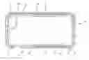
FIG. 4 is a cross-section in the plane of the device of a full case with the arrangement of FIG. 3.
DETAILED DESCRIPTION
FIG. 1 shows a small proportion of the case to illustrate the principle of the present invention. The whole case will run around the entire periphery of the device D.
The simplest design is typified in FIG. 1 which is a single material 1, in this case TPU (for example BASF Elastollan), which is provided with a number of inwardly extending ribs 2 which, as shown, have a semi-circular cross-section in the plane of the device and extend across the width of the band. The ribs in this example have a width of 2 mm, a depth of 1.5 mm and a spacing of 3 mm.
The same basic structure is observed in FIG. 2 which is in accordance with the invention, this time in a two part layer. The TPU forms the outer layer while an inner layer 3 formed in a dual injection process or as an insert mold is formed of a viscoelastic polymer which is softer than the TPU (for example, a TPE such as Kraiburg Thermolast K or a PU foam such as BASF Elastoflex). This time, the inwardly projecting ribs 2 are provided in the viscoelastic polymer layer 3. The viscoelastic polymer layer 3 also has a number of inwardly projecting ribs 4 which are embedded in the TPU layer 1.
The third case shown in FIG. 3 also in accordance with the invention adds to the second case of FIG. 2, a hard outer shell 5 which is a rigid polymer case (for example Bayer Makrolon). As shown in FIG. 3, this may only be present in certain regions where higher hardness is beneficial.
The manner in which the example shown in FIG. 3 is applied to a full case is shown with reference to FIG. 4. It will be appreciated that the examples of FIGS. 1 and 2 can be applied in the same manner, in The method of FIG. 2 omitting the outer shell 5, and in The method of FIG. 1 with all of the case being formed of a single layer of thermoplastic polymer 1.
In the full case shown in FIG. 4, the TPU material 1 forms the bulk of the casing including the majority of the rear face 6. This is lined with a layer of viscoelastic polymer 3 which extends across a portion of the rear face 6 and up the sides of the majority of the case. There are regions 7 and 8 in FIG. 4 where the viscoelastic polymer is absent and the only material is the TPU so as to allow access to the buttons in the side of the device in region 7 and the ports for the charger plug and headphone jack in region 8. The ribs 2 are present particularly at the corners of the device to provide maximum cushioning in these regions. Running along the majority of each side of the case are truncated ribs 2′ so that the case does not contact the device in these regions during normal use thereby further isolating the sides from impact on the screen.
The interface between the TPU 1 and viscoelastic polymer 5 has a plurality of rectangular ribs 9 protruding inwardly from the viscoelastic polymer 5. These ribs 9 have a rectangular profile in cross-section, the width of which is at least twice their depth.
The case is completed by the rigid polymer layer 5 which extends along the majority of each side of the case. There is also a ring of rigid polymer 10 surrounding an orifice 11 which provides a window for the rear facing camera, sensor and LED flash.
As can be seen from FIG. 4, the casing is designed to provide maximum cushioning in the corner regions. However, along the long side portions, the case is largely held away from the device and has enhanced rigidity afforded by the rigid polymer layer 5.
Claims
1. A method for manufacturing a case for a mobile device with a screen, the case comprising a band arranged to surround the edge of the device, the method comprising:
supplying a band having a layer of flexible polymer;
inserting the band of flexible polymer with the layer of flexible polymer in an insert mold method to form an insert mold;
applying discrete discontinuous and unconnected damping material on the layer of the flexible polymer of the insert mold via a dual injection process or using the layer of flexible polymer of the insert mold, the damping material being softer than the flexible polymer, the damping material having a plurality of integrally formed protrusions projecting inwardly from a substantial portion of the inner periphery of the band to engage with the device,
wherein the protrusions are arranged such that, in normal use there is substantially no contact between the band and the device other than through the protrusions;
wherein the protrusions are provided at least in the corner regions of the case, and
wherein there are regions around the band where the damping material is absent such that the damping material does not extend continuously around the band and the only material is the layer of flexible polymer.
2. The method of claim 1, wherein there are no protrusions, or shorter protrusions along portions of the longer edges of the case such that the case will not contact the device in these regions in normal use.
3. The method of claim 1, wherein the protrusions are ribs extending generally across the depth of the band and have a curved cross-section when viewed in a section taken in the plane of the device.
4. The method of claim 3, wherein the curved cross-section is substantially semi-circular.
5. The method of claim 1, wherein the damping material is provided with a plurality of outwardly projecting protrusions which are imbedded in the flexible polymer material.
6. The method of claim 5, wherein the outwardly projecting protrusions are ribs which are rectangular in cross-section when viewed in a section taken in the plane of the device.
7. The method of claim 1, wherein a layer of material harder than the flexible polymer material is provided outside of the flexible polymer material.
8. The method of claim 1, wherein the flexible polymer layer has a Shore A hardness range of 70 to 90.
9. The method of claim 1, wherein the layer of damping material has a Shore A hardness range of 0 to 70.
10. The method of claim 7, wherein the layer of material harder than the flexible polymer material has a hardness range of 75 Shore A to 85 Shore D.
11. The method of claim 1, wherein the protrusions are robust enough, so that, when dropped from 7 meters onto a hard surface, the protrusions will prevent contact between the device and the material between adjacent protrusions.
12. The method of claim 1, wherein each protrusion protrudes for a depth at least 0.5 mm from the band, has a width greater than the depth and a pitch between adjacent protrusions which is greater than twice the width.
13. The method of claim 12, wherein the depth of each protrusion is at least 1 mm.
14. The method of claim 8, wherein the protrusions are robust enough, so that, when dropped from 7 meters onto a hard surface, the protrusions will prevent contact between the device and the material between adjacent protrusions.
15. The method of claim 9, wherein the protrusions are robust enough, so that, when dropped from 7 meters onto a hard surface, the protrusions will prevent contact between the device and the material between adjacent protrusions.
16. The method of claim 1, further comprising a rear face defined by the band and wherein the damping material is confined to the band and is not present on the rear face.
17. The method of claim 1, wherein the discrete discontinuous and unconnected damping material is inseparable from the layer of flexible polymer.
18. The method of claim 1, wherein the damping material is bonded to the layer of flexible polymer.
19. The method of claim 17, wherein the band is a single piece formed from the layer of flexible polymer with the discrete discontinuous and unconnected damping material.
Images & Drawings included:


Sources:
- United States Patent and Trademark Office - verify current appl. status at the USPTO↗
Recent applications in this class:
- » 20250280935 2025-09-11
SECURITY BAG AND METHOD OF USE - » 20250255390 2025-08-14
PROTECTIVE ANTENNA PACKAGE AND TRANSPORT UNIT THEREFOR - » 20250234971 2025-07-24
CASE FOR A PERSONAL ELECTRONIC DEVICE - » 20250234970 2025-07-24
CASE FOR A PERSONAL ELECTRONIC DEVICE - » 20250213016 2025-07-03
PROTECTIVE CASE FOR MOBILE DEVICE AND MOBILE DEVICE WITH THE PROTECTIVE CASE - » 20250204660 2025-06-26
UNIVERSAL DEVICE HOLDER - » 20250204659 2025-06-26
ELECTRONIC DEVICE PROTECTIVE COVER - » 20250204658 2025-06-26
VR silicone integrated handle protective casing - » 20250143427 2025-05-08
DEPLOYABLE SUPPORT APPARATUS - » 20250134226 2025-05-01
ELECTRONIC DEVICE PROTECTIVE COVER
Recent applications for this Assignee:
- » 20180027938 2018-02-01
Case for a mobile device - » 20170303653 2017-10-26
Method of manufacturing a case of a mobile electronic device - » 20160359517 2016-12-08
Radio frequency properties of a case for a communications device - » 20160352875 2016-12-01
Radio frequency properties of a case for a communications device - » 14730711 2016-03-22
Radio frequency properties of a case for a communications device