ELECTRONIC SYSTEM FOR POWER CONSUMPTION MANAGEMENT OF APPLIANCES
US20180048152A1
2018-02-15
15/792,268
2017-10-24
Abstract:
An electronic system for power consumption management of one or more domestic appliances is routinely informed on actual energy tariff through a network control unit or through a predetermined time-table stored in the system. A user interface of the electronic system is provided where the user can set his preference concerning the switch-on time of each appliance and/or function thereof and read the related estimated energy consumption and/or energy cost of the appliance working program.
Inventors:
- MATTEO SANTINATO 7 🇮🇹 Albignasego, Italy
- ETTORE ARIONE 11 🇮🇹 LEGGIUNO, Italy
- GIORGIO BRAGHINI 4 🇮🇹 VARESE, Italy
Interested in similar patents?
Get notified when new applications in this technology area are published.
Classification:
H02J3/008 » CPC main
Circuit arrangements for ac mains or ac distribution networks involving trading of energy or energy transmission rights
Y04S50/10 » CPC further
Market activities related to the operation of systems integrating technologies related to power network operation or related to communication or information technologies Energy trading, including energy flowing from end-user application to grid
Y02B70/3225 » CPC further
Technologies for an efficient end-user side electric power management and consumption; Systems integrating technologies related to power network operation and communication or information technologies for improving the carbon footprint of the management of residential or tertiary loads, i.e. smart grids as climate change mitigation technology in the buildings sector, including also the last stages of power distribution and the control, monitoring or operating management systems at local level Demand response systems, e.g. load shedding, peak shaving
Y04S20/222 » CPC further
Management or operation of end-user stationary applications or the last stages of power distribution; Controlling, monitoring or operating thereof; End-user application control systems Demand response systems, e.g. load shedding, peak shaving
H02J3/00 IPC
Circuit arrangements for ac mains or ac distribution networks
H02J3/14 » CPC further
Circuit arrangements for ac mains or ac distribution networks for adjusting voltage in ac networks by changing a characteristic of the network load by switching loads on to, or off from, network, e.g. progressively balanced loading
Description
CROSS REFERENCE TO RELATED APPLICATIONS
The present application is a continuation of U.S. application Ser. No. 12/886,618, filed Sep. 21, 2010, which is continuation of U.S. application Ser. No. 10/447,359, filed May 29, 2003, which claims the benefit of European Patent Application No. 02011668.7, filed May 31, 2002, all of which are incorporated herein by reference in their entirety.
BACKGROUND OF THE INVENTION
Field of the Invention
The present invention relates to an electronic system for power/energy consumption management of one or more domestic appliances, which is routinely informed on actual energy tariff through a network control unit.
Description of the Related Art
JP-A-2000214186 discloses a power consumption management apparatus for enterprise with an electronic unit that measures total amount of power consumed by electrical equipment. EP-A-1136829 discloses a process for measuring the energy consumption of a plurality of appliances connected to a power network in which each switching-on or switching-off of each appliance is detected through a specific high frequency signal injected in the network. DE-A-3935102 discloses a process for varying the load on a power system by injecting signals into the system using an audio frequency signal generator.
Daily energy demand isn't flat; peaks of energy are generated during the day which creates variable demand and increases a utility company's charge to consumers. To avoid dangerous blackouts utility companies are searching for ways to smooth energy demand by offering advantages to customers who are able to control their power consumption.
Consequently, it would be advantageous to design a new generation of appliances that are able to manage power consumption with different tariffs on the base of signed power supply contract.
One of the aims of the present invention is to implement a power management system to help the consumer in saving energy and money. Another object of the present invention is to make the user aware of potential energy cost savings in selecting different delayed switch-on times for each appliance. A further object of the present invention is to provide a system which comprises a user interface through which the user may also input a predetermined energy cost saving target referred to a certain fixed time (week, month), the system being able to select the proper times for switching-on the appliances in order to get the energy-savings target.
SUMMARY OF THE INVENTION
The electronic system according to the invention is characterized by the features listed in the appended claims. Thanks to such features, the electronic system according to the invention may:
-
- allow a powerful and direct user interface designed for a simple and easy understanding in using energy profiles and priorities selected by the user;
- support customer energy—savings objectives (i.e. elaborate a new plan to save a certain amount in a week);
- avoid power shutoff due to energy demand peaks by setting dynamic priorities among products or product functions (i.e. delay defrost to reduce the power consumption); and
- manage the appliances in a coordinated way in order to execute the activities defined in a daily/weekly plan (i.e. start the washer to finish at 18:00 and start the dishwasher to finish before 7:00 by using the cheaper tariff)
The electronic system according to the present invention may also be able to interact with the utility company information center (thorough power line or TLC) to routinely collect information about contract terms and restrictions like daily/weekly/monthly/seasonally tariffs, peak limit and/or penalty.
In another embodiment, the electronic system may be able to negotiate with the utility company backend for a possible reduction of energy consumption in front of unplanned lack of power.
The electronic system according to the invention is preferably linked to so called “intelligent plugs” (i.e. plugs which can interrupt electrical supply to appliances on the basis of a specific signal on the power network) in agreement with priorities fixed by the user.
The electronic system may comprise the following hardware subsystems:
-
- display and keyboard: where the user can set his preferences, power priorities, fixed objectives/targets and read the estimated power consumption or warnings of the home appliances;
- microprocessor running a power management software;
- data transmission device (appl. modem) that permits the data connection with the appliances and intelligent plugs (wireless RF, bluetooth, 812.11b/a, wired and/or power line);
- power meter which can be an external device, integral with the network, in order to make possible its installation in a different place (for instance near the main power switch);
- optional serial/usb interface to exchange data with a personal computer or telecom modem.
BRIEF DESCRIPTION OF THE DRAWINGS
The present invention will be described in details with reference to the appended drawings in which:
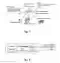
FIG. 1 is a schematic view which shows how the electronic system according to the invention interacts with the user, the appliance and other elements linked by a data transmission network;
FIG. 2 is a schematic view of a hardware subsystem of the electronic system according to the invention;
FIG. 3 is a schematic diagram showing a power management model according to the invention;
FIG. 4 is a schematic flow-chart showing the data flow of the power management system according to the invention; and
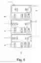
FIG. 5 is an example of user interface used with the electronic system according to the invention.
DETAILED DESCRIPTION
With reference to FIG. 1, the power management algorithm which drives the electronic system according to the invention can have two main functionalities identified by the user, an “on line” functionality and a “run time” functionality.
The “on line” functionality supports the customer through the display associated to the electronic system, in defining the initial settings of the system like:
-
- daily/weekly plan for appliances management. The power management algorithm analyses the requests and checks the feasibility taking into account the utility company contract limitations and the appliances energy consumption;
- objectives, appliances and function priorities inside appliance. Starting from the user's input the algorithm is able to elaborate and propose a new daily/weekly plan taking into account energy tariffs, utility company contract restrictions and number of appliances present in the network and their energy consumption. In front of any modification, requested by the user, of the proposed plan the algorithm elaborates the impact on the original objectives (for instance an increase of the energy cost);
- energy consumption and priority for appliances connected through intelligent plugs.
The “run time” functionality of the power management algorithm may perform at least the following activities:
-
- continuously process the customer settings and the utility tariffs to re-planning the daily activities at any time it detects a change;
- send commands to the appliances in order to complete the daily/weekly plan;
- continuously check the energy consumption by means of a meter device belonging to the electronic system to avoid critical situations due to energy consumption peaks that can generate dangerous shutoff. When information on energy consumption is not provided by the network, a device can be used which is formed by an instantaneous energy meter and by an appl. modem (FIG. 2). This latter allows an integration in the electronic system and a possible installation of the device nearby the main power switch. Two critical scenarios are considered:
1) Start of appliance. Each appliance before starting a program cycle asks for the authorization to the power management algorithm. The algorithm checks the actual energy consumption and verifies if the requested energy is available. When the requested energy is not available, the power management algorithm is able to negotiate with the appliance the possibility to run an energy cost saving function or to force the start of an alternative energy cost saving function. An alternative scenario can be that the power management algorithm stops (or pauses) low priority appliances in order to have enough energy to fulfil the request of higher priority device.
2) The energy consumption is higher than the security threshold. When the power management algorithm detects a high level of energy consumption, (over the security threshold), the algorithm may stop or pause the appliances or functions inside appliance with lower priority level. After a defined time and a complete disconnection of the appliances with priority 1, if the energy consumption is not yet below the security threshold the algorithm starts the procedure to start or pause the appliances with priority 2.
FIG. 3 shows the area of intervention and the methodology adopted by the power management algorithm to avoid shutoff. The security treshold 1, 2, . . . n are defined by the electronic control system on the basis of the input/targets selected by the user. The time threshold 2 is reached after a predetermined amount of time in which the energy consumption of home appliances is above the security threshold 1. This is due to a normal practice in shutting off if high power consumption level is maintained longer than a predetermined time. This is the reason why of the “L” shape of the zone of security threshold 2 and n.
As highlighted in FIG. 4 the interaction between the electronic system and the appliances is more or less sophisticated in relation of the “intelligence” of the appliance.
A “smart” appliance with power management (PM) features is able to provide the PM functionality also in a stand-alone mode. In fact in this case, the appliance is able to collect the actual energy consumption and manage the transaction to the status (i.e. normal function, energy cost saving function, pause and delayed start) as required by the energy availability. In addition, the smart appliances with PM features is able to coordinate its interventions with the global management led by the electronic system opening a negotiation cycle to maximize the appliances performances relatively to the available energy.
On the contrary, an “intelligent” appliance without PM features is able to provide the PM functionality only interacting with the electronic system hosted by a “smart” appliance or by a specific stand-alone device. The PM algorithm running in the electronic system is able to drive the appliances not only providing the start, stop and pause command but also running energy cost saving functions.
The electronic system can be used with traditional (or non-intelligent) appliances since these can be controlled by intelligent plugs and can participate actively to the PM process. Each intelligent plug is able to provide on/off functionality and if possible, to drive the energy consumption with continuous power regulation.
The electronic system can host a set of software algorithms that can run on different devices placed in house network or outside but “on line” connected. Examples of “in house” devices are:
-
- An ad hoc intelligent device connected in the home network.
- A smart appliance hosting the PM algorithms.
- A home gateway or a customer PC.
Alternatively, the PM algorithm can be also distributed on separated devices (for example the “on line” functionality can be on a PC to make easier the user interaction while the “run time” functionality can be hosted inside an appliance).
Warnings and alarms are foreseen every time that the PM algorithm detects a critical event, interacts with the appliances to avoid dangerous situation or finds problems to complete the forecasted daily/weekly energy-saving plan. These messages can be displayed in different ways on different devices for example:
-
- Graphic, alphanumerical and/or sound message for PC, appliance with high level display, gateway or stand alone display connected to the home network;
- Warning/alarm code and buzz for appliance equipped with more simple user interface.
When the electronic system is hosted in a “smart” appliance, the related software is essentially composed by:
-
- a NMT (Network Management Tool) program which is able to establish a reliable connection with other devices and find the sources of information that needs, and
- a “smart application” software that manages the power demand of the appliance by interpreting the energy tariffs and shows the available alternatives to customer on the user interface or by network/remote interrogations.
The NMT program starts at first time the user uses the appliance. This shell announces the appliance to the other smart appliances already working in the house (community) and integrates itself on the home network environment. The main goal of this software is to maintain the list of smart appliances that are working in the house, built the priority list and share the real time data to other software layers. The main goal of the “smart application” software shell is to avoid power shutdown reducing the instant power consumption before to reach the power peak limit or critical situations.
This application, before starting a working cycle of the appliance, checks if there is enough energy to avoid shutoff and eventually asks to other smart appliances, with lower priority, to reduce their power consumption.
The “smart application” software can support innovative services to increase the customer satisfaction likes:
-
- PxU (Pay for Use) functionality.
- Remote maintenance of the appliance.
In the preferred embodiment of the present invention (FIG. 5), the electronic system has a user interface preferably placed in an appliance. Such user interface has been designed to be extremely simple and easy to use. The idea is to add minimal modifications to standard user interface, since two keys are enough: the ‘selector’ key S and ‘remote’ key K.
Pressing the ‘selector’ key on the appliance, the display scrolls through a variety of opportunities showing the corresponding charges (Euro, $/cent or other currency). The user accepts a selection by pressing the usual ‘start’ key. The appliance will start its working based on the time (the input can be a delay time or the time on which the appliance has to start actually its program) and corresponding charge that was displayed.
The user interface may show the delay or the time when will start the service.
The optional ‘remote’ key is preferably added to permit the remote control feature and check the status of the appliance from cellular phone or browsing by Internet connection.
To explain more in detail the user interface, reference is made to its implementation in a washer (FIG. 5).
The customer sets the washing cycle by turning the program knob of the washer (not shown). Next, the selector key S is pressed and the user interface (UI) shows the charge C if the washing program is started immediately (delay=00—upper part of FIG. 5).
By pressing the selector key S again, the application program evaluates and shows the first alternative to save money.
Middle portion of FIG. 5 suggests to wait 2 hours and 20 min (display T) and to pay 60 eurocents (about $0.70) for the washing cycle. Now, the customer can accept the suggestion by pressing the ‘start’ key (not shown) or look for a new alternative by pressing the selector key S again.
The new alternative suggests to wait 8 hours and 20 min and to pay only 20 eurocents (about $0.23) for the washing cycle. Again, the customer can accept by pressing ‘start’ or select the first option by pressing the ‘Selector’ key again.
If the user presses more times the selector key the display scrolls between the alternatives.
The user accepts a selection by pressing the ‘start’ key. Then, the appliance will start running based on the time and corresponding charge that was displayed.
The introduction of the home electronic system for power consumption management provides benefits to both the utility company and customer.
The utility company takes advantages mainly from the possibility to interact “on line” with the house controlling actively the energy consumption in order to avoid the peaks and balance the energy demand during the day. This can be done by the utility company in two different interaction levels:
I. By sharing the home energy consumption value and the contract limits forcing the electronic system to maintain the energy demand under the upper limit.
II. By disconnecting more appliances in more houses. The electronic system represents the device to interface the home and negotiate switch off or energy cost saving functions for the connected appliances.
The main customer benefits are:
-
- Avoid shutoff or penalty due to peaks on home energy demand.
- Save money planning the use of appliances when energy tariffs are cheaper to exploit all opportunities of energy market deregulation.
The PM system is able to find the best planning taking into account the user needs and the energy cost tariffs imposed by the utility company.
Claims
We claim:1. An electronic system for power consumption management of a domestic appliance having at least one working cycle, the electronic system comprising:
a user interface comprising a display showing:
one of the at least one working cycles;
a first energy cost of executing the displayed working cycle at an immediate start time; and
an alternative start time for executing the displayed working cycle at a time that is different than the immediate start time, the alternative start time corresponding to a second energy cost of executing the displayed working cycle that is different than the first energy cost; and
a first input to select either the immediate start time or the alternative start time for the displayed working cycle;
wherein the displayed working cycle is executed by the domestic appliance at the selected start time and at the corresponding energy cost.
2. The electronic system of claim 1 wherein the display is configured to show the second energy cost.
3. The electronic system of claim 1 wherein the alternative start time comprises a delay of time or a time at which the displayed working cycle is to be executed.
4. The electronic system of claim 1 wherein the first input is part of the domestic appliance or remote from the domestic appliance.
5. The electronic system of claim 1 wherein the domestic appliance is connected with a data transmission network to receive energy cost information.
6. The electronic system of claim 1 wherein the domestic appliance comprises a clothes washing machine, a clothes dryer, a dishwasher, a refrigerator, a freezer, or an ice maker.
7. The electronic system of claim 1 comprising a second input to prompt the display to show additional alternative start times for executing the displayed working cycle.
8. An electronic system for power consumption management of a domestic appliance having at least one selectable working cycle, the electronic system comprising:
a display showing a first energy cost of executing a selected working cycle at a current time and a second energy cost of executing the selected working cycle at a future time;
a device connected with a data transmission network to receive energy cost information for the current time and the future time; and
a user interface having an input for selecting the current time or the future time to execute the selected working cycle based on the displayed energy costs;
wherein the cost of executing the selected working cycle is based on the received energy cost information.
9. The electronic system of claim 8 wherein the display is part of the domestic appliance or remote from the domestic appliance.
10. The electronic system of claim 8 wherein the future time comprises a delay of time or a time at which the selected working cycle is to be executed.
11. The electronic system of claim 8 wherein the input is part of the domestic appliance or remote from the domestic appliance.
12. The electronic system of claim 8 wherein the display is configured to scroll through energy costs for executing the selected working cycle at multiple different future times.
13. The electronic system of claim 8 wherein the domestic appliance comprises a clothes washing machine, a clothes dryer, a dishwasher, a refrigerator, a freezer, or an ice maker.
14. An electronic system for power consumption management of a domestic appliance having at least one working cycle, the system comprising:
a user interface displaying:
at least one working cycle;
an energy cost for executing one of the at least one displayed working cycles at a current switch-on time; and
a future switch-on time for executing the displayed working cycle, wherein an energy cost of executing the displayed working cycle at the future switch-on time is different than the energy cost of executing the displayed working cycle at the current switch-on time; and
an input for selecting the current switch-on time or the future switch-on time for executing the displayed working cycle;
wherein the current or the future switch-on time can be selected based on a user's cost preference for executing the displayed working cycle.
15. The electronic system of claim 14 wherein the user interface displays an energy cost of the future switch-on time.
16. The electronic system of claim 14 wherein the user interface is configured to allow a user to view a plurality of future start times having an energy cost of executing the displayed working cycle that is different than the current switch-on time.
17. The electronic system of claim 14 wherein the future switch-on time comprises a delay of time or a time at which the displayed working cycle is to be executed.
18. The electronic system of claim 14 wherein the input is part of the domestic appliance or remote from the domestic appliance.
19. The electronic system of claim 14 wherein the domestic appliance is connected with a data transmission network to receive energy cost information.
20. The electronic system of claim 14 wherein the domestic appliance comprises a clothes washing machine, a clothes dryer, a dishwasher, a refrigerator, a freezer, or an ice maker.
Images & Drawings included:


Sources:
- United States Patent and Trademark Office - verify current appl. status at the USPTO↗
Similar patent applications:
Recent applications in this class:
- » 20250174991 2025-05-29
METHOD AND APPARATUS TO FORM A VIRTUAL POWER GENERATION COLLECTIVE FROM A DISTRIBUTED NETWORK OF LOCAL GENERATION FACILITIES - » 20250149890 2025-05-08
MOVING AND STORING ENERGY BETWEEN UTILITY'S ENERGY DELIVERY NETWORKS - » 20250007284 2025-01-02
METHODS AND SYSTEMS FOR AN AUTOMATED UTILITY MARKETPLACE PLATFORM - » 20240170963 2024-05-23
BLOCKCHAIN-BASED ELECTRICITY TRADING METHOD AND SYSTEM IN VIRTUAL POWER PLANT ENVIRONMENT - » 20240097444 2024-03-21
HYBRID SYSTEM AND METHOD FOR DISTRIBUTED VIRTUAL POWER PLANTS INTEGRATED INTELLIGENT NET ZERO - » 20240030706 2024-01-25
Method and apparatus to form a virtual power generation collective from a distributed network of local generation facilities - » 20230352938 2023-11-02
METHODS, SYSTEMS, APPARATUSES, AND DEVICES FOR FACILITATING MANAGING INTERCONNECTION PROCESSES ON A POWER TRANSMISSION NETWORK - » 20230283074 2023-09-07
SYSTEMS AND METHODS FOR A WIRELESS SENSOR NETWORK - » 20230268735 2023-08-24
POWER TRADING SYSTEM AND MANAGEMENT APPARATUS - » 20230155381 2023-05-18
Blockchain-based electricity charge settlement method and system for energy storage station