Time delay toll system for charging piles and its method
US20180050596A1
2018-02-22
15/607,635
2017-05-29
✅ Patent granted
US 11,780,338 B2
2023-10-10
-
-
Eric D Lee
HOUTTEMAN LAW LLC
2037-07-10
Abstract:
The invention discloses a time delay toll system for charging piles, which can promote the electric automobile user to leave as early as possible or settle accounts as early as possible after the charging is end, improve the availability factor of the charging piles and parking stalls, and increase an efficiency of operation of the charging piles. The system includes: the charging state inspection module, which is configured to detect the magnitude of voltage of the communication cables of the charging piles, and send the magnitude of voltage to the microprocessor; the parking detection module, which is installed on the parking stall, and is configured to detect whether has an automobile on this parking stall; the microprocessor, which is configured to determine whether the charging is end according to the magnitude of voltage, if yes, then notify the timer to reckon by time, and send the module of deducting fees the time that the automobile stayed from the time beginning to the car's leaving; the module of deducting fees, which is configured to calculate the charge expense and time delay expense, and is configured to deduct the said charge expense and time delay expense from the user's fund. The method that adopts this time delay toll system for charging piles is also provided.
Assignee:
- Beijing X-Charge Co., Ltd. 1 🇨🇳 Beijing, China
Applicant:
Interested in similar patents?
Get notified when new applications in this technology area are published.
Classification:
G07B15/02 » CPC further
Arrangements or apparatus for collecting fares, tolls or entrance fees at one or more control points taking into account a variable factor such as distance or time, e.g. for passenger transport, parking systems or car rental systems
B60L53/11 » CPC main
Methods of charging batteries, specially adapted for electric vehicles; Charging stations or on-board charging equipment therefor; Exchange of energy storage elements in electric vehicles characterised by the energy transfer between the charging station and the vehicle DC charging controlled by the charging station, e.g. mode 4
H02J7/00032 » CPC further
Circuit arrangements for charging or depolarising batteries or for supplying loads from batteries characterised by data exchange
B60L2240/80 » CPC further
Control parameters of input or output; Target parameters Time limits
B60L2250/12 » CPC further
Driver interactions by confirmation, e.g. of the input
H02J2310/48 » CPC further
The network for supplying or distributing electric power characterised by its spatial reach or by the load; The network being an on-board power network, i.e. within a vehicle for electric vehicles [EV] or hybrid vehicles [HEV]
Y02T10/70 » CPC further
Road transport of goods or passengers; Other road transportation technologies with climate change mitigation effect Energy storage systems for electromobility, e.g. batteries
Y02T10/70 » CPC further
Road transport of goods or passengers; Other road transportation technologies with climate change mitigation effect Energy storage systems for electromobility, e.g. batteries
Y02T10/7072 » CPC further
Road transport of goods or passengers; Other road transportation technologies with climate change mitigation effect Electromobility specific charging systems or methods for batteries, ultracapacitors, supercapacitors or double-layer capacitors
Y02T10/7072 » CPC further
Road transport of goods or passengers; Other road transportation technologies with climate change mitigation effect Electromobility specific charging systems or methods for batteries, ultracapacitors, supercapacitors or double-layer capacitors
Y02T90/12 » CPC further
Enabling technologies or technologies with a potential or indirect contribution to GHG emissions mitigation; Technologies relating to charging of electric vehicles Electric charging stations
Y02T90/12 » CPC further
Enabling technologies or technologies with a potential or indirect contribution to GHG emissions mitigation; Technologies relating to charging of electric vehicles Electric charging stations
Y02T90/14 » CPC further
Enabling technologies or technologies with a potential or indirect contribution to GHG emissions mitigation; Technologies relating to charging of electric vehicles Plug-in electric vehicles
Y02T90/14 » CPC further
Enabling technologies or technologies with a potential or indirect contribution to GHG emissions mitigation; Technologies relating to charging of electric vehicles Plug-in electric vehicles
Y02T90/16 » CPC further
Enabling technologies or technologies with a potential or indirect contribution to GHG emissions mitigation; Technologies relating to charging of electric vehicles Information or communication technologies improving the operation of electric vehicles
Y02T90/16 » CPC further
Enabling technologies or technologies with a potential or indirect contribution to GHG emissions mitigation; Technologies relating to charging of electric vehicles Information or communication technologies improving the operation of electric vehicles
Y02T90/167 » CPC further
Enabling technologies or technologies with a potential or indirect contribution to GHG emissions mitigation; Technologies relating to charging of electric vehicles; Information or communication technologies improving the operation of electric vehicles Systems integrating technologies related to power network operation and communication or information technologies for supporting the interoperability of electric or hybrid vehicles, i.e. smartgrids as interface for battery charging of electric vehicles [EV] or hybrid vehicles [HEV]
Y04S30/14 » CPC further
Systems supporting specific end-user applications in the sector of transportation; Systems supporting the interoperability of electric or hybrid vehicles Details associated with the interoperability, e.g. vehicle recognition, authentication, identification or billing
B60L53/64 » CPC further
Methods of charging batteries, specially adapted for electric vehicles; Charging stations or on-board charging equipment therefor; Exchange of energy storage elements in electric vehicles; Monitoring or controlling charging stations Optimising energy costs, e.g. responding to electricity rates
G01R31/58 » CPC further
Arrangements for testing electric properties; Arrangements for locating electric faults; Arrangements for electrical testing characterised by what is being tested not provided for elsewhere; Testing of electric apparatus, lines, cables or components for short-circuits, continuity, leakage current or incorrect line connections Testing of lines, cables or conductors
H02J7/00 IPC
Circuit arrangements for charging or depolarising batteries or for supplying loads from batteries
B60L53/10 IPC
Methods of charging batteries, specially adapted for electric vehicles; Charging stations or on-board charging equipment therefor; Exchange of energy storage elements in electric vehicles characterised by the energy transfer between the charging station and the vehicle
Description
FIELD OF THE INVENTION
The present invention relates to a technical field of new energy vehicles, and particularly relates to a time delay toll system for charging piles, and a method that adopts this system.
BACKGROUND OF THE INVENTION
With the development of the technology and the science, due to the energy saving and environmental protection of the new energy vehicles, new energy vehicles are more and more popular in common people. Therefore, in the current parking lot, more and more charging piles are used.
However, the current charging piles are often faced with such a problem: the user is still occupied for a long time and do not leave after charging is end. This condition greatly hindered the use of the other customers, and resulted in a waste of charging parking spaces and charging piles.
SUMMARY OF THE INVENTION
For the above technical problem, the present invention provides a time delay toll system for charging piles, which can promote the electric automobile user to leave as early as possible or settle accounts as early as possible after his charging is end, and can improve the availability factor of charging piles and parking stalls, and can increase the efficiency of operation of charging piles.
The technical solution of the present invention is, the system includes:
the charging state inspection module, which is configured to detect the magnitude of voltage of the communication cables of charging piles, and send the magnitude of voltage to the microprocessor;
the parking detection module, which is installed on the parking stall, and is configured to detect whether has an automobile on this parking stall;
the microprocessor, which is configured to determine whether the charging is end according to the magnitude of voltage, if yes, then notify the timer to reckon by time, and send the module of deducting fees the time that the automobile stayed from the beginning to leaving:
the module of deducting fees, which is configured to calculate charge expense and time delay expense, and is configured to deduct the said charge expense and time delay expense from the user's fund.
The present invention also provides a method that adopts this time delay toll system for charging piles, wherein the said charging pile is AC charging pile, and including the following steps:
-
- (1) Starting charging, the said magnitude of voltage is 6V;
- (2) When charging is end, and when the said magnitude of voltage is 9V or 6V, perform the step (3), otherwise perform the step (5);
- (3) the timer begins to reckon by time, and gets the time that the automobile stayed from the time beginning to the car's leaving;
- (4) calculating charge expense and time delay expense;
- (5) the said magnitude of voltage is 12V;
- (6) deducting the said charge expense and time delay expense from the user's fund.
Or the present invention also provides a method that adopts this time delay toll system for charging piles, wherein the said charging pile is DC charging pile, including the following steps.
-
- (I) Starting charging, the said magnitude of voltage is 4V;
- (II) When charging is end, and when the said magnitude of voltage is 4V, perform the step (III), otherwise perform the step (V),
- (III) the timer begins to reckon by time, and gets the time that the automobile stayed from the time beginning to the car's leaving;
- (IV) calculating charge expense and time delay expense;
- (V) the said magnitude of voltage is 6V;
- (VI) deducting the said charge expense and time delay expense from the user's fund.
By the judgment for the connection status of hardware and flexible toll mechanism, through the economic lever means, the present invention can promote the electric vehicle users to leave as soon as possible after their charging is end, make the charging piles and the parking spaces to the next users, improve the efficiency of the use of parking and charging piles, and increase the operation efficiency of charging piles.
BRIEF DESCRIPTION OF THE DRAWINGS
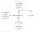
FIG. 1 is a schematic view of the time delay toll system for charging piles according to the present invention;
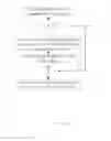
FIG. 2 is a flow chart, showing a method that adopts the time delay toll system for charging piles according to the present invention, wherein the said charging pile is AC charging pile.
DETAILED DESCRIPTION OF THE PREFERRED EMBODIMENTS
As shown as FIG. 1, this time delay toll system for charging piles, the system includes:
the charging state inspection module, which is configured to detect the magnitude of voltage of the communication cables of the charging piles, and send the magnitude of voltage to the microprocessor;
the parking detection module, which is installed on the parking stall, and is configured to detect whether has an automobile on this parking stall;
the microprocessor, which is configured to determine whether the charging is end according to the magnitude of voltage, if yes, then notify the tinier to reckon by time, and send the module of deducting fees the time that the automobile stayed from the beginning to leaving;
the module of deducting fees, which is configured to calculate charge expense and time delay expense, and is configured to deduct the said charge expense and time delay expense from the user's fund.
By the judgment for the connection status of hardware and flexible toll mechanism, through the economic lever means, the present invention can promote the electric vehicle users to leave as soon as possible after the charging is end, make charging piles and parking spaces to the next users, improve the efficiency of the use of parking and the charging piles, and increase the operation efficiency of charging piles.
Preferably, the system also includes the communication module, which is configured to connect to the microprocessor, when the timer begins to reckon by time, send the time delay expense to the user by the communication module.
Preferably, the said charging pile is AC charging pile, when the said magnitude of voltage is 12V, the microprocessor is confirmed not to connect with a vehicle; when the said magnitude of voltage is 9V or 6V, the microprocessor is confirmed to connect with a vehicle.
Preferably, the said charging pile is DC charging pile, when the said magnitude of voltage is 6V, the microprocessor is confirmed not to connect with a vehicle; when the said magnitude of voltage is 4V, the microprocessor is confirmed to connect with a vehicle.
As shown as FIG. 2, the present invention also provides a method that adopts this time delay toll system for charging piles, wherein the said charging pile is AC charging pile, including the following steps:
-
- (1) Starting charging, the said magnitude of voltage is 6V;
- (2) When the charging is end, and when the said magnitude of voltage is 9V or 6V, perform the step (3), otherwise perform the step (5);
- (3) the timer begins to reckon by time, and gets the time that the automobile stayed from the time beginning to the car's leaving;
- (4) calculating the charge expense and the time delay expense;
- (5) the said magnitude of voltage is 12V;
- (6) deducting the said charge expense and time delay expense from the user's fund.
Preferably, the said step (3) also includes a grace time, if a vehicle can leave the parking stall, the time delay expense is zero.
Or the present invention also provides a method that adopts this time delay toll system for charging piles, wherein the said charging pile is DC charging pile, including the following steps.
-
- (I) Starting charging, the said magnitude of voltage is 4V;
- (II) When the charging is end, and when the said magnitude of voltage is 4V, perform the step (III), other wise perform the step (V),
- (III) the timer begins to reckon by time, and gets the time that the automobile stayed from the time beginning to the car's leaving;
- (IV) calculating the charge expense and the time delay expense;
- (V) the said magnitude of voltage is 6V;
- (VI) deducting the said charge expense and time delay expense from the user's fund.
Preferably, the said step (III) also includes a grace time, if a vehicle can leave the parking stall, the time delay expense is zero.
A specific example is given below.
(1) Judge whether a vehicle is connected to a charging pile according to CC, CP.
According to the definition of the AC charging pile CP and DC charging pile CC in the national standard GB/T18487, GB/T20234: the voltage of the AC charging pile CC communication cable is DC 12V voltage at no-load, and the voltage is less than 12V (9V, 6V when inserting the socket) after the vehicle is connected.
the voltage of DC charging pile CP communication cable is DC 6V voltage at no-load, and the voltage is less than 6V (4V when inserting the socket, 6V when pressing the button of the head of charging device) after the vehicle is connected.
(2) As shown as Table 1, the charging pile provides the real-time feedback of the CC and CP voltage status to the internal program and the remote system to determine whether the vehicle is connected. At the same time, according to the following logic to determine whether need to charge the time delay expense.
| TABLE 1 | |||
| the voltage of | the voltage of | ||
| AC charging | DC charging | ||
| pile CC commu- | corresponding | pile CP commu- | corresponding |
| nication cable | state | nication cable | state |
| 12 V | don't connect | 6 V don't | don't connect |
| connect | to a vehicle | ||
| 9 V have | have connected | 9 V the button | have connected |
| connected | to a vehicle | is pressed | to the socket, |
| the switch is | |||
| pressed | |||
| 6 V have | have connected | 4 V have | have connected |
| connected | to a vehicle | connected | to a vehicle |
(3) When the charging pile hardware judged that the user has finished the charging (fill or manual stop), sends notifications to the user according to “grace time” preset by the software, and requires the user to draw charging device and moves the car in the grace time, at the same time starts the countdown.
(4) When the user cuts off connection (draw charging device) in delay time fee grace time, the system does not charge any delay cost.
(5) When the user stays beyond delay time fee grace time, the system will begin to a new timing or record, and charge according to the system set.
(6) Delay fee setting, can calculate in accordance with the time as a unit, or can single one-time billing.
It is main in the present invention to judge whether this user cuts off connection, that is, whether CP returns to 12V after charging. In other countries except China, it is generally Combo combination, that is, one interface for AC and DC. In DC it also can be determined whether inserting gun or drawing gun by CP definition in AC, as shown as Table 2.
| TABLE 2 | |||
| Standard number | SAE J1772 (Combo) | IEC 62916 (Combo) | GB/T (18487. 1-2015) |
| AC | connecting pin | CP | CP | CP |
| charging | check the | disconnect | 12 V ± 1 V | 12 V ± 1 V | 12 ± 0.8 V |
| pile | status of | (drawing gun) | |||
| voltage by | connect but not charge | 9 ± 1 V | 9 V ± 1 V | 9 ± 0.8 V | |
| pin | start charging (Charging | 6 ± 1 V | 6 V ± 1 V | 6 ± 0.8 V | |
| area ventilation not | |||||
| required) | |||||
| start charging (Charging | 3 ± 1 V | 3 V ± 1 V | / | ||
| area ventilation required) | |||||
| not drawing gun after | 6 ± 1 V 9 V ± 1 V | 6 ± 1 V 9 V ± 1 V | 6 V ± 0.8 V 9 ± 0.8 V | ||
| charging (Not disconnect | |||||
| connect, but Charging stop) | |||||
Also, charging piles can obtain the user's vehicle battery information by communication with the vehicle's communication cables (Can, PLC or CCS protocol), and when battery SoC value is arrived set value, notify the user.
According to CC, CP, or other cables that confirm to communicate with a vehicle (each country is different to define the interface, CC: connect confirm, CP: control portion confirm), the charging piles can determine the connection status of the vehicle and the charging piles.
The above stated is only preferable embodiments of the present invention, and it should be noted that the above preferable embodiments do not limit the present invention. The claimed scope of the present invention should be based on that defined by the claims. For a skilled person in this technical field, without departing from spirit and scope of the present invention, any improvement and amendment can be made, and these improvement and amendment should belong to the claimed scope of the present invention.
Claims
1. A time delay toll system for charging piles, characterized in that, the system includes:
the charging state inspection module, which is configured to detect the magnitude of voltage of the communication cables of the charging piles, and send the magnitude of the voltage to the microprocessor;
the parking detection module, which is installed on the parking stall, and is configured to detect whether has an automobile on this parking stall;
the microprocessor, which is configured to determine whether the charging is end according to the magnitude of voltage, if yes, then notify the timer to reckon by time, and send the module of deducting fees the time that the automobile stayed from the time beginning to the car's leaving;
the module of deducting fees, which is configured to calculate the charge expense and the time delay expense, and is configured to deduct the said charge expense and time delay expense from the user's fund.
2. The time delay toll system for charging piles according to the claim 1, characterized in that, the system also includes the communication module, which is configured to connect to the microprocessor, when the timer begins to reckon by time, send the time delay expense to the user by the communication module.
3. The time delay toll system for charging piles according to the claim 2, characterized in that, the said charging pile is AC charging pile, when the said magnitude of voltage is 12V, the microprocessor is confirmed not to connect with a vehicle; when the said magnitude of voltage is 9V or 6V, the microprocessor is confirmed to connect with a vehicle.
4. The time delay toll system for charging piles according to the claim 2, characterized in that, the said charging pile is DC charging pile, when the said magnitude of voltage is 6V, the microprocessor is confirmed not to connect with a vehicle; when the said magnitude of voltage is 4V, the microprocessor is confirmed to connect with a vehicle.
5. A method that adopts the time delay toll system for charging piles according to the claim 3, characterized in that, including the following steps:
(1) Starting charging, the said magnitude of voltage is 6V;
(2) When the charging is end, and when the said magnitude of voltage is 9V or 6V, perform the step (3), otherwise perform the step (5);
(3) the timer begins to reckon by time, and gets the time that the automobile stayed from the time beginning to the car's leaving;
(4) Calculating the charge expense and the time delay expense;
(5) the said magnitude of voltage is 12V;
(6) deducting the said charge expense and time delay expense from the user's fund.
6. The method according to the claim 5, characterized in that, the said step (3) also includes a grace time, if a vehicle can leave the parking stall, the time delay expense is zero.
7. A method that adopts the time delay toll system for charging piles according to the claim 4, characterized in that, including the following steps:
(I) Starting charging, the said magnitude of voltage is 4V;
(II) When the charging is end, and when the said magnitude of voltage is 4V, perform the step (III), otherwise perform the step (V);
(III) the timer begins to reckon by time, and gets the time that the automobile stayed from the time beginning to the car's leaving;
(IV) calculating the charge expense and time delay expense;
(V) the said magnitude of voltage is 6V;
(VI) deducting the said charge expense and time delay expense from the user's fund.
8. The method according to the claim 7, characterized in that, the said step (III) also includes a grace time, if a vehicle can leave the parking stall, the time delay expense is zero.
Images & Drawings included:

Sources:
- United States Patent and Trademark Office - verify current appl. status at the USPTO↗
Recent applications in this class:
- » 20200070665 2020-03-05
Adaptive Reservoir Charging Station - » 20200031234 2020-01-30
SELF-CHARGING ELECTRIC CAR SYSTEM - » 20190299790 2019-10-03
Methods and devices for thermal control during charging of electric vehicles - » 20190202299 2019-07-04
Battery charging method and apparatus - » 20190184836 2019-06-20
Ultra-fast charge profile for an electric vehicle - » 20190160954 2019-05-30
Method and system for providing a charging park having a plurality of charging points - » 20190160953 2019-05-30
Apparatus and method for flexible DC fast charging of an electrified vehicle - » 20190143821 2019-05-16
System and method for battery charging - » 20190143820 2019-05-16
Maximum current calculation and power prediction for a battery pack - » 20190126761 2019-05-02
Configurable battery pack for series and parallel charging using switching