SMART SCAN PERIPHERAL
US20180068145A1
2018-03-08
15/258,065
2016-09-07
Abstract:
A smart scan peripheral is capable of attaching to a mobile computing device (e.g., a smartphone) allowing the resulting combination to be used like a traditional gun scanner. The scan handle peripheral does not require a power source or any electrical connection to the mobile computing device but can operate to still relay trigger pull information to a running application on the mobile computing device. This scan handle peripheral makes use of a magnetometer found in the mobile computing device by moving a magnet into the vicinity of the electromagnetic field generated by the magnetometer. As the handle magnet enters the magnetic field around the magnetometer, a software application in the processor of the mobile computing device monitoring the magnetometer readings and when a disruption is detected, a trigger event is sent to the processor to trigger an operation such as a barcode scanning event. In an alternative embodiment, a passive near field communication (NFC) tag 600 is mounted on an actuator which slides into a readable position of an NFC reader on the mobile computing device to cause a trigger event.
Interested in similar patents?
Get notified when new applications in this technology area are published.
Classification:
G06K7/146 » CPC main
Methods or arrangements for sensing record carriers, e.g. for reading patterns by electromagnetic radiation, e.g. optical sensing; by corpuscular radiation using light without selection of wavelength, e.g. sensing reflected white light; Methods for optical code recognition the method including quality enhancement steps
H04W88/02 » CPC further
Devices specially adapted for wireless communication networks, e.g. terminals, base stations or access point devices Terminal devices
G06K19/06028 » CPC further
Record carriers for use with machines and with at least a part designed to carry digital markings characterised by the kind of the digital marking, e.g. shape, nature, code with optically detectable marking one-dimensional coding using bar codes
G06K7/10881 » CPC further
Methods or arrangements for sensing record carriers, e.g. for reading patterns by electromagnetic radiation, e.g. optical sensing; by corpuscular radiation by scanning of the records by radiation in the optical part of the electromagnetic spectrum further details of bar or optical code scanning devices constructional details of hand-held scanners
G06K7/14 IPC
Methods or arrangements for sensing record carriers, e.g. for reading patterns by electromagnetic radiation, e.g. optical sensing; by corpuscular radiation using light without selection of wavelength, e.g. sensing reflected white light
H04W4/00 IPC
Services specially adapted for wireless communication networks; Facilities therefor
G06K7/10 IPC
Methods or arrangements for sensing record carriers, e.g. for reading patterns by electromagnetic radiation, e.g. optical sensing; by corpuscular radiation
G06K19/06 IPC
Record carriers for use with machines and with at least a part designed to carry digital markings characterised by the kind of the digital marking, e.g. shape, nature, code
Description
FIELD OF THE INVENTION
The present invention relates to a scan handle peripheral for a mobile computing device to create a scanner assembly.
BACKGROUND
With advances in integrated circuit, microprocessor, networking, and communication technologies in recent years, increasing number of mobile devices have been developed and adopted by the consumers. Mobile devices are typically compact, and many are palm-sized, to increase the ease of their carriage, thereby allowing their users to keep the mobile devices with them, as they move from place to place. Increasingly, mobile devices are capable of storing vast quantity of information and performing a wide range of functions.
SUMMARY
Accordingly, in an exemplary embodiment, there is disclosed a peripheral housing capable of being attached to a mobile computing device comprising: a handle having a trigger; a platform coupled to the handle having attachments configured to receive the mobile computing device; and an actuator coupled to the trigger and capable of responding to the depression of the trigger by moving a magnet from a first position to a second position along the platform.
In another exemplary embodiment, there is disclosed a peripheral housing and mobile computing device system comprising: the peripheral housing having a handle with a trigger, a platform coupled to the handle having attachments configured to receive the mobile computing device, and an actuator coupled to the trigger and capable of responding to the depression of the trigger by moving a magnet from a first position to a second position along the platform; and the mobile computing device having at least one magnetometer creating a magnetic field near the second position, and a processor configured to detect interruption of the magnetic field to signal an event.
In another exemplary embodiment, there is disclosed a method of signaling an event to start a bar code scan from a mobile computing device: attaching the mobile computing device to a platform of a peripheral housing; depressing a trigger at least once on a handle of the peripheral housing to move a magnet from a first position on the peripheral housing to a second position in a vicinity of an electromagnetic field created by at least one sensor in the mobile computing device; detecting by the processor of the mobile computing device that an interruption of the electromagnetic field has occurred to signal that a bar code scan should take place.
In another exemplary embodiment, there is disclosed a peripheral housing capable of being attached to a mobile computing device comprising: a handle having a trigger; a platform coupled to the handle having attachments configured to receive the mobile computing device; and an actuator coupled to the trigger and capable of responding to the depression of the trigger by moving a near field communication (NFC) tag from a first position to a second position along the platform.
The foregoing illustrative summary, as well as other exemplary objectives and/or advantages of the invention, and the manner in which the same are accomplished, are further explained within the following detailed description and its accompanying drawings.
BRIEF DESCRIPTION OF THE DRAWINGS
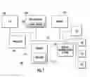
FIG. 1 schematically depicts an exemplary mobile computing device 100 in accordance with the present disclosure.
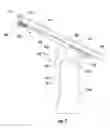
FIG. 2 illustrates a scan handle peripheral 200 configured to attach to a mobile computing device 100 allowing it to be used like a traditional gun scanner.
FIG. 3 illustrates that a magnetometer 124 is commonly found in the same area in most mobile computing devices which is in the upper left corner of the device 100 (when held in a portrait orientation).
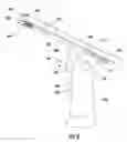
FIG. 4 illustrates that when the trigger 205 of the scan handle peripheral 200 is pulled, a handle magnet 206 slides in the direction of arrow 208 into the vicinity of a corresponding mobile computing device magnetometer 124 that is mounted on the scan handle peripheral 200.
FIG. 5 illustrates the internal workings of the scan handle peripheral 200 which include a fulcrum 212 and a spring mechanism 214 that are capable of sliding a handle magnet 206 into the vicinity of the magnetic field of the magnetometer 124 on a trigger 205 pull.
FIG. 6 illustrates an alternative embodiment wherein a passive near field communication (NFC) handle tag 600 slides into position with a near field communication (NFC) reader 130 on the device 100.
DETAILED DESCRIPTION
Disclosed herein is a smart scan handle peripheral which is capable of attaching to a mobile computing device (e.g., a smartphone) allowing the resulting combination to be used as a gun scanner. The scan handle peripheral does not require a power source or any electrical connection to the mobile computing device but can still operate to relay trigger pull information from the operator to a running application on the mobile computing device. The scan handle peripheral makes use of a magnetometer found in the mobile computing device by moving a magnet into the vicinity of the electromagnetic field generated by the magnetometer. As the handle magnet enters the magnetic field around the magnetometer, a software application running in the processor of the mobile computing device monitors the magnetometer readings and when a disruption is detected, a trigger event (or pattern of trigger events) is sent to the processor of the mobile computing device to trigger an operation such as a barcode scanning.
FIG. 1 schematically depicts an exemplary mobile computing device 100 in accordance with the present disclosure. The mobile computing device 100 may be a smartphone (e.g., Apple® iPhone, Android® phone), mobile tablet (e.g., Apple® iPad), or the like. The mobile computing device 100 includes a processor (or processors) 110 having a set of stored programs (“applications”), which when executed by the processor, provides users with Internet functionality, for instance, to access websites, to establish remote terminal sessions on another device, to send and receive text messages, make phone calls, to watch videos, etc. Processor(s) 110 is communicatively coupled with the user interface system 102 having touch screen/visual display 105, a memory 112 coupled to a database 114, a camera 116, a wireless communication system 118 and an input/output (I/O) module 120, and as well as other components 124, 126, 128 and 130 described below. Exemplary mobile computing devices 100 may include a system bus 122 and/or one or more interface circuits (not shown) for coupling the processor 110 and other components (e.g., user interface system 102, memory 112, camera system 116, wireless communication system 118 and I/O module) to the system bus 122 and to each other. Typically, the processor 110 is configured to execute instructions and to carry out operations associated with the mobile computing device 100. For example, using instructions retrieved from the memory 112 (e.g., a memory block), the processor 110 may control the reception and manipulation of input and output data between components of the mobile computing device 100. When the mobile computing device 100 is an imager or scanner, the processor 110 is configured to capture from the camera 116 an image depicting a code symbol; displaying the image on the visual display 105; and determining whether the code symbol in the image is readable by the processor 110. The processor 110 typically operates with an operating system to execute computer code and produce and use data. The operating system, other computer code, and data may reside within the memory 112 that is operatively coupled to the processor 110. The memory 112 generally provides a place to store computer code and data that are used by the mobile computing device 100. The memory 112 may include Read-Only Memory (ROM), Random-Access Memory (RAM), a hard disk drive, and/or other non-transitory storage media. The operating system, other computer code, and data may also reside on a removable non-transitory storage medium that is loaded or installed onto the mobile computing device 100 when needed. The wireless communication system 118 enables the mobile computing device 100 to communicate with a wireless network, such as a cellular network (e.g., a GSM network, a CDMA network, or an LTE network), a local area network (LAN), and/or an ad hoc network.
The addition of a scanning mobile plugin to the processor 100 and memory 112 allows the mobile computing device 100 to operate as an image scanner. For example, the plugin may be Honeywell's SwiftDecoder Mobile barcode decoding Application Programming Interface (API) created for smartphones. The SwiftDecoder API is a bar code decoding software which may be used to decode one-dimensional, two-dimensional, and postal bar codes.
The mobile computing device 100 further includes a magnetometer 124 (or a plurality of magnetometer sensors 124) which is a measurement instrument used for two general purposes: to measure the magnetization of a magnetic material like a ferromagnet, or to measure the strength and, in some cases, the direction of a magnetic field at a point in space. In mobile computing devices the magnetometer 124 is usually a three axis sensor. The magnetometer 124 in the mobile computing device 100 utilizes modern solid state technology to create a miniature Hall-effect sensor that detects the Earth's magnetic field along three perpendicular axes X, Y, and Z. The magnetometer 124 produces voltage which is proportional to the strength and polarity of the magnetic field along the axis each sensor is directed. The sensed voltage is converted to a digital signal representing the magnetic field intensity. Other technologies used for the magnetometer 124 may include giant magnetoresistance (GMR), magnetic tunneling junction (MTJ) sensing, anisotropic magnetoresistance (AMR), and Lorentz forces. The magnetometer 124 may be enclosed in a small electronic chip that helps to correct the raw magnetic measurements using tilt information from the sensor. In addition to general rotational information, the magnetometer is crucial for detecting the relative orientation of the mobile computing device 100 relative to the Earth's magnetic north. The mobile computing device 100 may include additional inertial sensors such as an accelerometer(s) and gyroscope(s). The inertial sensors 126 and 128 can keep track of the mobile computing device 100 location if, for example, the operator takes the mobile computing device 100 into a place where no wireless system works. The magnetometer 124 can determine direction, the accelerometer 126 can report how fast the mobile computing device is moving in that direction, and the gyroscope 128 can sense turning motions. Together, these sensors can determine the mobile computing device 100 location with no outside inputs for a certain period of time. Device 100 may further include a Near Field Communication (NFC) reader 130 capable of reading radio frequency identification tags when they come within range (e.g., less than 5 centimeters typically).
Mobile computing devices 100 such as smartphones are widely used to scan barcodes and many other types of indicia. These scanning use cases are not just limited to consumers, as it is becoming more common for an enterprise to utilize smartphones due to their superior aesthetics, increased durability, great developer ecosystems, and very capable camera systems 116. Although a smartphone can be a very effective tool for many barcode scanning operations, they are still not as ergonomic as traditional hand held scanning form factors, such as the gun form factor. This disclosure proposes a scan handle peripheral 200 as shown in FIG. 2 that can attach to a mobile computing device 100 allowing it to be used like a traditional gun scanner. The scan handle peripheral 200 does not require a power source or any electrical connection to the mobile computing device 100 (not shown in FIG. 2) but can operate to still relay trigger pull information to a running application on the mobile computing device 100. The scan handle peripheral 200 makes use of the magnetometer 124 found in all modern smartphones. As discussed above, the magnetometer 124 may be used to detect the Earth's magnetic field. The magnetometer creates a small, surrounding electromagnetic field 125. When the magnetometer 124 is used in conjunction with inertial sensors (126 and 128), the processor 110 can understand the orientation of the mobile computing device 100. This capability is used for navigation purposes as well as several other use cases such as indoor positioning, augmented reality, etc.
Referring again to FIG. 2, a detachable scan handle peripheral 200 with trigger may use an inexpensive mechanical system operating inside a gun shaped housing 202. The housing 202 has a handle 202a attached to a platform 202b. Scan handle peripheral 200 is configured to mount the mobile computing device 100 (not shown in FIG. 2) on the platform 202b using attachments 203 (e.g., straps, clips and the like) allowing the operator to hold it like a gun. The scan handle peripheral 200 can accommodate a variety of different size mobile computing device form factors by arranging the attachments 203 in a plurality of settings.
In operation, the angle of the platform 202b and thus the angle of scanning may be adjusted by turning a scan angle adjustor (e.g., a knob or dial) 204 on the side of the scan handled peripheral. The adjustor 204 may allow the platform 202b to be angled in relation to the handle 202a. The platform 202b may be adjusted to a plurality of positions to obtain the best angle for scanning by the camera system 116. FIG. 3 illustrates that a magnetometer 124 which is commonly found in the same area in most mobile computing devices. When held in a portrait orientation, the magnetometer is typically in the upper left hand corner of the device 100. As shown in FIG. 4, when the trigger 205 is pulled (or depressed) by the operator, a handle magnet 206 mounted on an actuator 207 slides from a first position in the direction of arrow 208 to a second position located in the vicinity of where a corresponding magnetometer 124 would be located on the mobile computing device 100 when it is in a mounted position on the platform 202b. As the handle magnet 206 moves into the second position it enters the magnetic field 125 around the magnetometer 124. A magnetometer monitoring software application in the processor 110 of the mobile computing device monitors the magnetometer 124 readings and when a disruption is detected, a trigger event is sent to the scanning software application (e.g., SwiftDecoder API) in the processor 110. The patterns of the field disruptions (e.g., frequency, duration, number of times, etc.) due to the handle magnet 206 are continually monitored by the monitoring magnetometer software application. Trigger pull events could be used for any operation but would most commonly be used to trigger a barcode scanning event.
The magnetometer 124 may also be located in other areas of the device 100. As the handle magnet 206 changes positions it will still affect the readings of the magnetometer 124 even if the magnetometer 124 is not in the upper left hand corner of the device 100 and these interruptions would then be observed by the magnetometer monitoring software application on the device 100.
A number of different mechanical techniques could be used to slide the handle magnet 206 from the first position into the second position on a trigger pull (as shown by arrows 210). One embodiment as shown in FIG. 5 illustrates a fulcrum 212 which is held in place by a spring mechanism 214. A pull of the trigger 205 by the operator slides the actuator 207 forward resulting in the handle magnet 206 moving from its first resting position to a second position behind the magnetometer 124.
The magnetometer monitoring software application running on processor 110 listens for a plurality of trigger 204 related events such as the following. The operator may pull and release the trigger 205 in different trigger pull patterns to fire different types of events in the scanning software application. The magnetometer monitoring software application could detect several types of events such as OnTriggerDown, OnTriggerUp, OnTriggerPull, OnTriggerLongPull, OnTriggerDoubleTap, and OnTriggerTrippleTap based on the interruptions in the magnetic field 125 of the magnetometer 124. The scanning software application is configured to respond to these events. For example, a trigger pull (i.e., OnTriggerDown) could start a barcode scanning event and letting the trigger up (i.e., OnTriggerUp) could stop the barcode scan event. The use of a double tap of the trigger 205 by the operator may toggle the flash for the scan. A triple tap and/or a long double tap of the trigger 205 may be used to indicate another event. The magnetometer monitoring software application monitors the magnetometer 124 readings and looks for changes to the ambient magnetic field 125 (typically significant changes due to the handle magnet 206 entering the magnetic field 125). When a change in the magnetic field 125 is detected, the magnetometer monitoring software application fires the appropriate events to any listeners such as the scanning software application. This scanning software application could be included within the SwiftDecoder Mobile API, which is a barcode scanning API for smart devices created by Honeywell.
FIG. 6 illustrates an alternative embodiment wherein a passive near field communication (NFC) (or radio frequency identification (RFID)) tag 600 (i.e., a handle tag instead of a handle magnet) mounted on an actuator 207 slides into a readable position of an NFC reader 130 (instead of a magnetometer) on the device 100. API software in the processor 110 may be configured to monitor the NFC reader 130 and interpret when and with what patterns (e.g., frequency, duration, number of times, etc.) tag 600 moves into range 602 of the reader 130.
Since this scan handle peripheral 200 does not need to be powered or electronically connected to the device 100 thus not require any electronic components within the housing, it could be produced very inexpensively.
To supplement the present disclosure, this application incorporates entirely by reference the following commonly assigned patents, patent application publications, and patent applications:
- U.S. Pat. No. 6,832,725; U.S. Pat. No. 7,128,266;
- U.S. Pat. No. 7,159,783; U.S. Pat. No. 7,413,127;
- U.S. Pat. No. 7,726,575; U.S. Pat. No. 8,294,969;
- U.S. Pat. No. 8,317,105; U.S. Pat. No. 8,322,622;
- U.S. Pat. No. 8,366,005; U.S. Pat. No. 8,371,507;
- U.S. Pat. No. 8,376,233; U.S. Pat. No. 8,381,979;
- U.S. Pat. No. 8,390,909; U.S. Pat. No. 8,408,464;
- U.S. Pat. No. 8,408,468; U.S. Pat. No. 8,408,469;
- U.S. Pat. No. 8,424,768; U.S. Pat. No. 8,448,863;
- U.S. Pat. No. 8,457,013; U.S. Pat. No. 8,459,557;
- U.S. Pat. No. 8,469,272; U.S. Pat. No. 8,474,712;
- U.S. Pat. No. 8,479,992; U.S. Pat. No. 8,490,877;
- U.S. Pat. No. 8,517,271; U.S. Pat. No. 8,523,076;
- U.S. Pat. No. 8,528,818; U.S. Pat. No. 8,544,737;
- U.S. Pat. No. 8,548,242; U.S. Pat. No. 8,548,420;
- U.S. Pat. No. 8,550,335; U.S. Pat. No. 8,550,354;
- U.S. Pat. No. 8,550,357; U.S. Pat. No. 8,556,174;
- U.S. Pat. No. 8,556,176; U.S. Pat. No. 8,556,177;
- U.S. Pat. No. 8,559,767; U.S. Pat. No. 8,599,957;
- U.S. Pat. No. 8,561,895; U.S. Pat. No. 8,561,903;
- U.S. Pat. No. 8,561,905; U.S. Pat. No. 8,565,107;
- U.S. Pat. No. 8,571,307; U.S. Pat. No. 8,579,200;
- U.S. Pat. No. 8,583,924; U.S. Pat. No. 8,584,945;
- U.S. Pat. No. 8,587,595; U.S. Pat. No. 8,587,697;
- U.S. Pat. No. 8,588,869; U.S. Pat. No. 8,590,789;
- U.S. Pat. No. 8,596,539; U.S. Pat. No. 8,596,542;
- U.S. Pat. No. 8,596,543; U.S. Pat. No. 8,599,271;
- U.S. Pat. No. 8,599,957; U.S. Pat. No. 8,600,158;
- U.S. Pat. No. 8,600,167; U.S. Pat. No. 8,602,309;
- U.S. Pat. No. 8,608,053; U.S. Pat. No. 8,608,071;
- U.S. Pat. No. 8,611,309; U.S. Pat. No. 8,615,487;
- U.S. Pat. No. 8,616,454; U.S. Pat. No. 8,621,123;
- U.S. Pat. No. 8,622,303; U.S. Pat. No. 8,628,013;
- U.S. Pat. No. 8,628,015; U.S. Pat. No. 8,628,016;
- U.S. Pat. No. 8,629,926; U.S. Pat. No. 8,630,491;
- U.S. Pat. No. 8,635,309; U.S. Pat. No. 8,636,200;
- U.S. Pat. No. 8,636,212; U.S. Pat. No. 8,636,215;
- U.S. Pat. No. 8,636,224; U.S. Pat. No. 8,638,806;
- U.S. Pat. No. 8,640,958; U.S. Pat. No. 8,640,960;
- U.S. Pat. No. 8,643,717; U.S. Pat. No. 8,646,692;
- U.S. Pat. No. 8,646,694; U.S. Pat. No. 8,657,200;
- U.S. Pat. No. 8,659,397; U.S. Pat. No. 8,668,149;
- U.S. Pat. No. 8,678,285; U.S. Pat. No. 8,678,286;
- U.S. Pat. No. 8,682,077; U.S. Pat. No. 8,687,282;
- U.S. Pat. No. 8,692,927; U.S. Pat. No. 8,695,880;
- U.S. Pat. No. 8,698,949; U.S. Pat. No. 8,717,494;
- U.S. Pat. No. 8,717,494; U.S. Pat. No. 8,720,783;
- U.S. Pat. No. 8,723,804; U.S. Pat. No. 8,723,904;
- U.S. Pat. No. 8,727,223; U.S. Pat. No. D702,237;
- U.S. Pat. No. 8,740,082; U.S. Pat. No. 8,740,085;
- U.S. Pat. No. 8,746,563; U.S. Pat. No. 8,750,445;
- U.S. Pat. No. 8,752,766; U.S. Pat. No. 8,756,059;
- U.S. Pat. No. 8,757,495; U.S. Pat. No. 8,760,563;
- U.S. Pat. No. 8,763,909; U.S. Pat. No. 8,777,108;
- U.S. Pat. No. 8,777,109; U.S. Pat. No. 8,779,898;
- U.S. Pat. No. 8,781,520; U.S. Pat. No. 8,783,573;
- U.S. Pat. No. 8,789,757; U.S. Pat. No. 8,789,758;
- U.S. Pat. No. 8,789,759; U.S. Pat. No. 8,794,520;
- U.S. Pat. No. 8,794,522; U.S. Pat. No. 8,794,525;
- U.S. Pat. No. 8,794,526; U.S. Pat. No. 8,798,367;
- U.S. Pat. No. 8,807,431; U.S. Pat. No. 8,807,432;
- U.S. Pat. No. 8,820,630; U.S. Pat. No. 8,822,848;
- U.S. Pat. No. 8,824,692; U.S. Pat. No. 8,824,696;
- U.S. Pat. No. 8,842,849; U.S. Pat. No. 8,844,822;
- U.S. Pat. No. 8,844,823; U.S. Pat. No. 8,849,019;
- U.S. Pat. No. 8,851,383; U.S. Pat. No. 8,854,633;
- U.S. Pat. No. 8,866,963; U.S. Pat. No. 8,868,421;
- U.S. Pat. No. 8,868,519; U.S. Pat. No. 8,868,802;
- U.S. Pat. No. 8,868,803; U.S. Pat. No. 8,870,074;
- U.S. Pat. No. 8,879,639; U.S. Pat. No. 8,880,426;
- U.S. Pat. No. 8,881,983; U.S. Pat. No. 8,881,987;
- U.S. Pat. No. 8,903,172; U.S. Pat. No. 8,908,995;
- U.S. Pat. No. 8,910,870; U.S. Pat. No. 8,910,875;
- U.S. Pat. No. 8,914,290; U.S. Pat. No. 8,914,788;
- U.S. Pat. No. 8,915,439; U.S. Pat. No. 8,915,444;
- U.S. Pat. No. 8,916,789; U.S. Pat. No. 8,918,250;
- U.S. Pat. No. 8,918,564; U.S. Pat. No. 8,925,818;
- U.S. Pat. No. 8,939,374; U.S. Pat. No. 8,942,480;
- U.S. Pat. No. 8,944,313; U.S. Pat. No. 8,944,327;
- U.S. Pat. No. 8,944,332; U.S. Pat. No. 8,950,678;
- U.S. Pat. No. 8,967,468; U.S. Pat. No. 8,971,346;
- U.S. Pat. No. 8,976,030; U.S. Pat. No. 8,976,368;
- U.S. Pat. No. 8,978,981; U.S. Pat. No. 8,978,983;
- U.S. Pat. No. 8,978,984; U.S. Pat. No. 8,985,456;
- U.S. Pat. No. 8,985,457; U.S. Pat. No. 8,985,459;
- U.S. Pat. No. 8,985,461; U.S. Pat. No. 8,988,578;
- U.S. Pat. No. 8,988,590; U.S. Pat. No. 8,991,704;
- U.S. Pat. No. 8,996,194; U.S. Pat. No. 8,996,384;
- U.S. Pat. No. 9,002,641; U.S. Pat. No. 9,007,368;
- U.S. Pat. No. 9,010,641; U.S. Pat. No. 9,015,513;
- U.S. Pat. No. 9,016,576; U.S. Pat. No. 9,022,288;
- U.S. Pat. No. 9,030,964; U.S. Pat. No. 9,033,240;
- U.S. Pat. No. 9,033,242; U.S. Pat. No. 9,036,054;
- U.S. Pat. No. 9,037,344; U.S. Pat. No. 9,038,911;
- U.S. Pat. No. 9,038,915; U.S. Pat. No. 9,047,098;
- U.S. Pat. No. 9,047,359; U.S. Pat. No. 9,047,420;
- U.S. Pat. No. 9,047,525; U.S. Pat. No. 9,047,531;
- U.S. Pat. No. 9,053,055; U.S. Pat. No. 9,053,378;
- U.S. Pat. No. 9,053,380; U.S. Pat. No. 9,058,526;
- U.S. Pat. No. 9,064,165; U.S. Pat. No. 9,064,167;
- U.S. Pat. No. 9,064,168; U.S. Pat. No. 9,064,254;
- U.S. Pat. No. 9,066,032; U.S. Pat. No. 9,070,032;
- U.S. Design Pat. No. D716,285;
- U.S. Design Pat. No. D723,560;
- U.S. Design Pat. No. D730,357;
- U.S. Design Pat. No. D730,901;
- U.S. Design Pat. No. D730,902;
- U.S. Design Pat. No. D733,112;
- U.S. Design Pat. No. D734,339;
- International Publication No. 2013/163789;
- International Publication No. 2013/173985;
- International Publication No. 2014/019130;
- International Publication No. 2014/110495;
- U.S. Patent Application Publication No. 2008/0185432;
- U.S. Patent Application Publication No. 2009/0134221;
- U.S. Patent Application Publication No. 2010/0177080;
- U.S. Patent Application Publication No. 2010/0177076;
- U.S. Patent Application Publication No. 2010/0177707;
- U.S. Patent Application Publication No. 2010/0177749;
- U.S. Patent Application Publication No. 2010/0265880;
- U.S. Patent Application Publication No. 2011/0202554;
- U.S. Patent Application Publication No. 2012/0111946;
- U.S. Patent Application Publication No. 2012/0168511;
- U.S. Patent Application Publication No. 2012/0168512;
- U.S. Patent Application Publication No. 2012/0193423;
- U.S. Patent Application Publication No. 2012/0203647;
- U.S. Patent Application Publication No. 2012/0223141;
- U.S. Patent Application Publication No. 2012/0228382;
- U.S. Patent Application Publication No. 2012/0248188;
- U.S. Patent Application Publication No. 2013/0043312;
- U.S. Patent Application Publication No. 2013/0082104;
- U.S. Patent Application Publication No. 2013/0175341;
- U.S. Patent Application Publication No. 2013/0175343;
- U.S. Patent Application Publication No. 2013/0257744;
- U.S. Patent Application Publication No. 2013/0257759;
- U.S. Patent Application Publication No. 2013/0270346;
- U.S. Patent Application Publication No. 2013/0287258;
- U.S. Patent Application Publication No. 2013/0292475;
- U.S. Patent Application Publication No. 2013/0292477;
- U.S. Patent Application Publication No. 2013/0293539;
- U.S. Patent Application Publication No. 2013/0293540;
- U.S. Patent Application Publication No. 2013/0306728;
- U.S. Patent Application Publication No. 2013/0306731;
- U.S. Patent Application Publication No. 2013/0307964;
- U.S. Patent Application Publication No. 2013/0308625;
- U.S. Patent Application Publication No. 2013/0313324;
- U.S. Patent Application Publication No. 2013/0313325;
- U.S. Patent Application Publication No. 2013/0342717;
- U.S. Patent Application Publication No. 2014/0001267;
- U.S. Patent Application Publication No. 2014/0008439;
- U.S. Patent Application Publication No. 2014/0025584;
- U.S. Patent Application Publication No. 2014/0034734;
- U.S. Patent Application Publication No. 2014/0036848;
- U.S. Patent Application Publication No. 2014/0039693;
- U.S. Patent Application Publication No. 2014/0042814;
- U.S. Patent Application Publication No. 2014/0049120;
- U.S. Patent Application Publication No. 2014/0049635;
- U.S. Patent Application Publication No. 2014/0061306;
- U.S. Patent Application Publication No. 2014/0063289;
- U.S. Patent Application Publication No. 2014/0066136;
- U.S. Patent Application Publication No. 2014/0067692;
- U.S. Patent Application Publication No. 2014/0070005;
- U.S. Patent Application Publication No. 2014/0071840;
- U.S. Patent Application Publication No. 2014/0074746;
- U.S. Patent Application Publication No. 2014/0076974;
- U.S. Patent Application Publication No. 2014/0078341;
- U.S. Patent Application Publication No. 2014/0078345;
- U.S. Patent Application Publication No. 2014/0097249;
- U.S. Patent Application Publication No. 2014/0098792;
- U.S. Patent Application Publication No. 2014/0100813;
- U.S. Patent Application Publication No. 2014/0103115;
- U.S. Patent Application Publication No. 2014/0104413;
- U.S. Patent Application Publication No. 2014/0104414;
- U.S. Patent Application Publication No. 2014/0104416;
- U.S. Patent Application Publication No. 2014/0104451;
- U.S. Patent Application Publication No. 2014/0106594;
- U.S. Patent Application Publication No. 2014/0106725;
- U.S. Patent Application Publication No. 2014/0108010;
- U.S. Patent Application Publication No. 2014/0108402;
- U.S. Patent Application Publication No. 2014/0110485;
- U.S. Patent Application Publication No. 2014/0114530;
- U.S. Patent Application Publication No. 2014/0124577;
- U.S. Patent Application Publication No. 2014/0124579;
- U.S. Patent Application Publication No. 2014/0125842;
- U.S. Patent Application Publication No. 2014/0125853;
- U.S. Patent Application Publication No. 2014/0125999;
- U.S. Patent Application Publication No. 2014/0129378;
- U.S. Patent Application Publication No. 2014/0131438;
- U.S. Patent Application Publication No. 2014/0131441;
- U.S. Patent Application Publication No. 2014/0131443;
- U.S. Patent Application Publication No. 2014/0131444;
- U.S. Patent Application Publication No. 2014/0131445;
- U.S. Patent Application Publication No. 2014/0131448;
- U.S. Patent Application Publication No. 2014/0133379;
- U.S. Patent Application Publication No. 2014/0136208;
- U.S. Patent Application Publication No. 2014/0140585;
- U.S. Patent Application Publication No. 2014/0151453;
- U.S. Patent Application Publication No. 2014/0152882;
- U.S. Patent Application Publication No. 2014/0158770;
- U.S. Patent Application Publication No. 2014/0159869;
- U.S. Patent Application Publication No. 2014/0166755;
- U.S. Patent Application Publication No. 2014/0166759;
- U.S. Patent Application Publication No. 2014/0168787;
- U.S. Patent Application Publication No. 2014/0175165;
- U.S. Patent Application Publication No. 2014/0175172;
- U.S. Patent Application Publication No. 2014/0191644;
- U.S. Patent Application Publication No. 2014/0191913;
- U.S. Patent Application Publication No. 2014/0197238;
- U.S. Patent Application Publication No. 2014/0197239;
- U.S. Patent Application Publication No. 2014/0197304;
- U.S. Patent Application Publication No. 2014/0214631;
- U.S. Patent Application Publication No. 2014/0217166;
- U.S. Patent Application Publication No. 2014/0217180;
- U.S. Patent Application Publication No. 2014/0231500;
- U.S. Patent Application Publication No. 2014/0232930;
- U.S. Patent Application Publication No. 2014/0247315;
- U.S. Patent Application Publication No. 2014/0263493;
- U.S. Patent Application Publication No. 2014/0263645;
- U.S. Patent Application Publication No. 2014/0267609;
- U.S. Patent Application Publication No. 2014/0270196;
- U.S. Patent Application Publication No. 2014/0270229;
- U.S. Patent Application Publication No. 2014/0278387;
- U.S. Patent Application Publication No. 2014/0278391;
- U.S. Patent Application Publication No. 2014/0282210;
- U.S. Patent Application Publication No. 2014/0284384;
- U.S. Patent Application Publication No. 2014/0288933;
- U.S. Patent Application Publication No. 2014/0297058;
- U.S. Patent Application Publication No. 2014/0299665;
- U.S. Patent Application Publication No. 2014/0312121;
- U.S. Patent Application Publication No. 2014/0319220;
- U.S. Patent Application Publication No. 2014/0319221;
- U.S. Patent Application Publication No. 2014/0326787;
- U.S. Patent Application Publication No. 2014/0332590;
- U.S. Patent Application Publication No. 2014/0344943;
- U.S. Patent Application Publication No. 2014/0346233;
- U.S. Patent Application Publication No. 2014/0351317;
- U.S. Patent Application Publication No. 2014/0353373;
- U.S. Patent Application Publication No. 2014/0361073;
- U.S. Patent Application Publication No. 2014/0361082;
- U.S. Patent Application Publication No. 2014/0362184;
- U.S. Patent Application Publication No. 2014/0363015;
- U.S. Patent Application Publication No. 2014/0369511;
- U.S. Patent Application Publication No. 2014/0374483;
- U.S. Patent Application Publication No. 2014/0374485;
- U.S. Patent Application Publication No. 2015/0001301;
- U.S. Patent Application Publication No. 2015/0001304;
- U.S. Patent Application Publication No. 2015/0003673;
- U.S. Patent Application Publication No. 2015/0009338;
- U.S. Patent Application Publication No. 2015/0009610;
- U.S. Patent Application Publication No. 2015/0014416;
- U.S. Patent Application Publication No. 2015/0021397;
- U.S. Patent Application Publication No. 2015/0028102;
- U.S. Patent Application Publication No. 2015/0028103;
- U.S. Patent Application Publication No. 2015/0028104;
- U.S. Patent Application Publication No. 2015/0029002;
- U.S. Patent Application Publication No. 2015/0032709;
- U.S. Patent Application Publication No. 2015/0039309;
- U.S. Patent Application Publication No. 2015/0039878;
- U.S. Patent Application Publication No. 2015/0040378;
- U.S. Patent Application Publication No. 2015/0048168;
- U.S. Patent Application Publication No. 2015/0049347;
- U.S. Patent Application Publication No. 2015/0051992;
- U.S. Patent Application Publication No. 2015/0053766;
- U.S. Patent Application Publication No. 2015/0053768;
- U.S. Patent Application Publication No. 2015/0053769;
- U.S. Patent Application Publication No. 2015/0060544;
- U.S. Patent Application Publication No. 2015/0062366;
- U.S. Patent Application Publication No. 2015/0063215;
- U.S. Patent Application Publication No. 2015/0063676;
- U.S. Patent Application Publication No. 2015/0069130;
- U.S. Patent Application Publication No. 2015/0071819;
- U.S. Patent Application Publication No. 2015/0083800;
- U.S. Patent Application Publication No. 2015/0086114;
- U.S. Patent Application Publication No. 2015/0088522;
- U.S. Patent Application Publication No. 2015/0096872;
- U.S. Patent Application Publication No. 2015/0099557;
- U.S. Patent Application Publication No. 2015/0100196;
- U.S. Patent Application Publication No. 2015/0102109;
- U.S. Patent Application Publication No. 2015/0115035;
- U.S. Patent Application Publication No. 2015/0127791;
- U.S. Patent Application Publication No. 2015/0128116;
- U.S. Patent Application Publication No. 2015/0129659;
- U.S. Patent Application Publication No. 2015/0133047;
- U.S. Patent Application Publication No. 2015/0134470;
- U.S. Patent Application Publication No. 2015/0136851;
- U.S. Patent Application Publication No. 2015/0136854;
- U.S. Patent Application Publication No. 2015/0142492;
- U.S. Patent Application Publication No. 2015/0144692;
- U.S. Patent Application Publication No. 2015/0144698;
- U.S. Patent Application Publication No. 2015/0144701;
- U.S. Patent Application Publication No. 2015/0149946;
- U.S. Patent Application Publication No. 2015/0161429;
- U.S. Patent Application Publication No. 2015/0169925;
- U.S. Patent Application Publication No. 2015/0169929;
- U.S. Patent Application Publication No. 2015/0178523;
- U.S. Patent Application Publication No. 2015/0178534;
- U.S. Patent Application Publication No. 2015/0178535;
- U.S. Patent Application Publication No. 2015/0178536;
- U.S. Patent Application Publication No. 2015/0178537;
- U.S. Patent Application Publication No. 2015/0181093;
- U.S. Patent Application Publication No. 2015/0181109;
- U.S. patent application Ser. No. 13/367,978 for a Laser Scanning Module Employing an Elastomeric U-Hinge Based Laser Scanning Assembly, filed Feb. 7, 2012 (Feng et al.);
- U.S. patent application Ser. No. 29/458,405 for an Electronic Device, filed Jun. 19, 2013 (Fitch et al.);
- U.S. patent application Ser. No. 29/459,620 for an Electronic Device Enclosure, filed Jul. 2, 2013 (London et al.);
- U.S. patent application Ser. No. 29/468,118 for an Electronic Device Case, filed Sep. 26, 2013 (Oberpriller et al.);
- U.S. patent application Ser. No. 14/150,393 for Indicia-reader Having Unitary Construction Scanner, filed Jan. 8, 2014 (Colavito et al.);
- U.S. patent application Ser. No. 14/200,405 for Indicia Reader for Size-Limited Applications filed Mar. 7, 2014 (Feng et al.);
- U.S. patent application Ser. No. 14/231,898 for Hand-Mounted Indicia-Reading Device with Finger Motion Triggering filed Apr. 1, 2014 (Van Horn et al.);
- U.S. patent application Ser. No. 29/486,759 for an Imaging Terminal, filed Apr. 2, 2014 (Oberpriller et al.);
- U.S. patent application Ser. No. 14/257,364 for Docking System and Method Using Near Field Communication filed Apr. 21, 2014 (Showering);
- U.S. patent application Ser. No. 14/264,173 for Autofocus Lens System for Indicia Readers filed Apr. 29, 2014 (Ackley et al.);
- U.S. patent application Ser. No. 14/277,337 for MULTIPURPOSE OPTICAL READER, filed May 14, 2014 (Jovanovski et al.);
- U.S. patent application Ser. No. 14/283,282 for TERMINAL HAVING ILLUMINATION AND FOCUS CONTROL filed May 21, 2014 (Liu et al.);
- U.S. patent application Ser. No. 14/327,827 for a MOBILE-PHONE ADAPTER FOR ELECTRONIC TRANSACTIONS, filed Jul. 10, 2014 (Hejl);
- U.S. patent application Ser. No. 14/334,934 for a SYSTEM AND METHOD FOR INDICIA VERIFICATION, filed Jul. 18, 2014 (Hejl);
- U.S. patent application Ser. No. 14/339,708 for LASER SCANNING CODE SYMBOL READING SYSTEM, filed Jul. 24, 2014 (Xian et al.);
- U.S. patent application Ser. No. 14/340,627 for an AXIALLY REINFORCED FLEXIBLE SCAN ELEMENT, filed Jul. 25, 2014 (Rueblinger et al.);
- U.S. patent application Ser. No. 14/446,391 for MULTIFUNCTION POINT OF SALE APPARATUS WITH OPTICAL SIGNATURE CAPTURE filed Jul. 30, 2014 (Good et al.);
- U.S. patent application Ser. No. 14/452,697 for INTERACTIVE INDICIA READER, filed Aug. 6, 2014 (Todeschini);
- U.S. patent application Ser. No. 14/453,019 for DIMENSIONING SYSTEM WITH GUIDED ALIGNMENT, filed Aug. 6, 2014 (Li et al.);
- U.S. patent application Ser. No. 14/462,801 for MOBILE COMPUTING DEVICE WITH DATA COGNITION SOFTWARE, filed on Aug. 19, 2014 (Todeschini et al.);
- U.S. patent application Ser. No. 14/483,056 for VARIABLE DEPTH OF FIELD BARCODE SCANNER filed Sep. 10, 2014 (McCloskey et al.);
- U.S. patent application Ser. No. 14/513,808 for IDENTIFYING INVENTORY ITEMS IN A STORAGE FACILITY filed Oct. 14, 2014 (Singel et al.);
- U.S. patent application Ser. No. 14/519,195 for HANDHELD DIMENSIONING SYSTEM WITH FEEDBACK filed Oct. 21, 2014 (Laffargue et al.);
- U.S. patent application Ser. No. 14/519,179 for DIMENSIONING SYSTEM WITH MULTIPATH INTERFERENCE MITIGATION filed Oct. 21, 2014 (Thuries et al.);
- U.S. patent application Ser. No. 14/519,211 for SYSTEM AND METHOD FOR DIMENSIONING filed Oct. 21, 2014 (Ackley et al.);
- U.S. patent application Ser. No. 14/519,233 for HANDHELD DIMENSIONER WITH DATA-QUALITY INDICATION filed Oct. 21, 2014 (Laffargue et al.);
- U.S. patent application Ser. No. 14/519,249 for HANDHELD DIMENSIONING SYSTEM WITH MEASUREMENT-CONFORMANCE FEEDBACK filed Oct. 21, 2014 (Ackley et al.);
- U.S. patent application Ser. No. 14/527,191 for METHOD AND SYSTEM FOR RECOGNIZING SPEECH USING WILDCARDS IN AN EXPECTED RESPONSE filed Oct. 29, 2014 (Braho et al.);
- U.S. patent application Ser. No. 14/529,563 for ADAPTABLE INTERFACE FOR A MOBILE COMPUTING DEVICE filed Oct. 31, 2014 (Schoon et al.);
- U.S. patent application Ser. No. 14/529,857 for BARCODE READER WITH SECURITY FEATURES filed Oct. 31, 2014 (Todeschini et al.);
- U.S. patent application Ser. No. 14/398,542 for PORTABLE ELECTRONIC DEVICES HAVING A SEPARATE LOCATION TRIGGER UNIT FOR USE IN CONTROLLING AN APPLICATION UNIT filed Nov. 3, 2014 (Bian et al.);
- U.S. patent application Ser. No. 14/531,154 for DIRECTING AN INSPECTOR THROUGH AN INSPECTION filed Nov. 3, 2014 (Miller et al.);
- U.S. patent application Ser. No. 14/533,319 for BARCODE SCANNING SYSTEM USING WEARABLE DEVICE WITH EMBEDDED CAMERA filed Nov. 5, 2014 (Todeschini);
- U.S. patent application Ser. No. 14/535,764 for CONCATENATED EXPECTED RESPONSES FOR SPEECH RECOGNITION filed Nov. 7, 2014 (Braho et al.);
- U.S. patent application Ser. No. 14/568,305 for AUTO-CONTRAST VIEWFINDER FOR AN INDICIA READER filed Dec. 12, 2014 (Todeschini);
- U.S. patent application Ser. No. 14/573,022 for DYNAMIC DIAGNOSTIC INDICATOR GENERATION filed Dec. 17, 2014 (Goldsmith);
- U.S. patent application Ser. No. 14/578,627 for SAFETY SYSTEM AND METHOD filed Dec. 22, 2014 (Ackley et al.);
- U.S. patent application Ser. No. 14/580,262 for MEDIA GATE FOR THERMAL TRANSFER PRINTERS filed Dec. 23, 2014 (Bowles);
- U.S. patent application Ser. No. 14/590,024 for SHELVING AND PACKAGE LOCATING SYSTEMS FOR DELIVERY VEHICLES filed Jan. 6, 2015 (Payne);
- U.S. patent application Ser. No. 14/596,757 for SYSTEM AND METHOD FOR DETECTING BARCODE PRINTING ERRORS filed Jan. 14, 2015 (Ackley);
- U.S. patent application Ser. No. 14/416,147 for OPTICAL READING APPARATUS HAVING VARIABLE SETTINGS filed Jan. 21, 2015 (Chen et al.);
- U.S. patent application Ser. No. 14/614,706 for DEVICE FOR SUPPORTING AN ELECTRONIC TOOL ON A USER'S HAND filed Feb. 5, 2015 (Oberpriller et al.);
- U.S. patent application Ser. No. 14/614,796 for CARGO APPORTIONMENT TECHNIQUES filed Feb. 5, 2015 (Morton et al.);
- U.S. patent application Ser. No. 29/516,892 for TABLE COMPUTER filed Feb. 6, 2015 (Bidwell et al.);
- U.S. patent application Ser. No. 14/619,093 for METHODS FOR TRAINING A SPEECH RECOGNITION SYSTEM filed Feb. 11, 2015 (Pecorari);
- U.S. patent application Ser. No. 14/628,708 for DEVICE, SYSTEM, AND METHOD FOR DETERMINING THE STATUS OF CHECKOUT LANES filed Feb. 23, 2015 (Todeschini);
- U.S. patent application Ser. No. 14/630,841 for TERMINAL INCLUDING IMAGING ASSEMBLY filed Feb. 25, 2015 (Gomez et al.);
- U.S. patent application Ser. No. 14/635,346 for SYSTEM AND METHOD FOR RELIABLE STORE-AND-FORWARD DATA HANDLING BY ENCODED INFORMATION READING TERMINALS filed Mar. 2, 2015 (Sevier);
- U.S. patent application Ser. No. 29/519,017 for SCANNER filed Mar. 2, 2015 (Zhou et al.);
- U.S. patent application Ser. No. 14/405,278 for DESIGN PATTERN FOR SECURE STORE filed Mar. 9, 2015 (Zhu et al.);
- U.S. patent application Ser. No. 14/660,970 for DECODABLE INDICIA READING TERMINAL WITH COMBINED ILLUMINATION filed Mar. 18, 2015 (Kearney et al.);
- U.S. patent application Ser. No. 14/661,013 for REPROGRAMMING SYSTEM AND METHOD FOR DEVICES INCLUDING PROGRAMMING SYMBOL filed Mar. 18, 2015 (Soule et al.);
- U.S. patent application Ser. No. 14/662,922 for MULTIFUNCTION POINT OF SALE SYSTEM filed Mar. 19, 2015 (Van Horn et al.);
- U.S. patent application Ser. No. 14/663,638 for VEHICLE MOUNT COMPUTER WITH CONFIGURABLE IGNITION SWITCH BEHAVIOR filed Mar. 20, 2015 (Davis et al.);
- U.S. patent application Ser. No. 14/664,063 for METHOD AND APPLICATION FOR SCANNING A BARCODE WITH A SMART DEVICE WHILE CONTINUOUSLY RUNNING AND DISPLAYING AN APPLICATION ON THE SMART DEVICE DISPLAY filed Mar. 20, 2015 (Todeschini);
- U.S. patent application Ser. No. 14/669,280 for TRANSFORMING COMPONENTS OF A WEB PAGE TO VOICE PROMPTS filed Mar. 26, 2015 (Funyak et al.);
- U.S. patent application Ser. No. 14/674,329 for AIMER FOR BARCODE SCANNING filed Mar. 31, 2015 (Bidwell);
- U.S. patent application Ser. No. 14/676,109 for INDICIA READER filed Apr. 1, 2015 (Huck);
- U.S. patent application Ser. No. 14/676,327 for DEVICE MANAGEMENT PROXY FOR SECURE DEVICES filed Apr. 1, 2015 (Yeakley et al.);
- U.S. patent application Ser. No. 14/676,898 for NAVIGATION SYSTEM CONFIGURED TO INTEGRATE MOTION SENSING DEVICE INPUTS filed Apr. 2, 2015 (Showering);
- U.S. patent application Ser. No. 14/679,275 for DIMENSIONING SYSTEM CALIBRATION SYSTEMS AND METHODS filed Apr. 6, 2015 (Laffargue et al.);
- U.S. patent application Ser. No. 29/523,098 for HANDLE FOR A TABLET COMPUTER filed Apr. 7, 2015 (Bidwell et al.);
- U.S. patent application Ser. No. 14/682,615 for SYSTEM AND METHOD FOR POWER MANAGEMENT OF MOBILE DEVICES filed Apr. 9, 2015 (Murawski et al.);
- U.S. patent application Ser. No. 14/686,822 for MULTIPLE PLATFORM SUPPORT SYSTEM AND METHOD filed Apr. 15, 2015 (Qu et al.);
- U.S. patent application Ser. No. 14/687,289 for SYSTEM FOR COMMUNICATION VIA A PERIPHERAL HUB filed Apr. 15, 2015 (Kohtz et al.);
- U.S. patent application Ser. No. 29/524,186 for SCANNER filed Apr. 17, 2015 (Zhou et al.);
- U.S. patent application Ser. No. 14/695,364 for MEDICATION MANAGEMENT SYSTEM filed Apr. 24, 2015 (Sewell et al.);
- U.S. patent application Ser. No. 14/695,923 for SECURE UNATTENDED NETWORK AUTHENTICATION filed Apr. 24, 2015 (Kubler et al.);
- U.S. patent application Ser. No. 29/525,068 for TABLET COMPUTER WITH REMOVABLE SCANNING DEVICE filed Apr. 27, 2015 (Schulte et al.);
- U.S. patent application Ser. No. 14/699,436 for SYMBOL READING SYSTEM HAVING PREDICTIVE DIAGNOSTICS filed Apr. 29, 2015 (Nahill et al.);
- U.S. patent application Ser. No. 14/702,110 for SYSTEM AND METHOD FOR REGULATING BARCODE DATA INJECTION INTO A RUNNING APPLICATION ON A SMART DEVICE filed May 1, 2015 (Todeschini et al.);
- U.S. patent application Ser. No. 14/702,979 for TRACKING BATTERY CONDITIONS filed May 4, 2015 (Young et al.);
- U.S. patent application Ser. No. 14/704,050 for INTERMEDIATE LINEAR POSITIONING filed May 5, 2015 (Charpentier et al.);
- U.S. patent application Ser. No. 14/705,012 for HANDS-FREE HUMAN MACHINE INTERFACE RESPONSIVE TO A DRIVER OF A VEHICLE filed May 6, 2015 (Fitch et al.);
- U.S. patent application Ser. No. 14/705,407 for METHOD AND SYSTEM TO PROTECT SOFTWARE-BASED NETWORK-CONNECTED DEVICES FROM ADVANCED PERSISTENT THREAT filed May 6, 2015 (Hussey et al.);
- U.S. patent application Ser. No. 14/707,037 for SYSTEM AND METHOD FOR DISPLAY OF INFORMATION USING A VEHICLE-MOUNT COMPUTER filed May 8, 2015 (Chamberlin);
- U.S. patent application Ser. No. 14/707,123 for APPLICATION INDEPENDENT DEX/UCS INTERFACE filed May 8, 2015 (Pape);
- U.S. patent application Ser. No. 14/707,492 for METHOD AND APPARATUS FOR READING OPTICAL INDICIA USING A PLURALITY OF DATA SOURCES filed May 8, 2015 (Smith et al.);
- U.S. patent application Ser. No. 14/710,666 for PRE-PAID USAGE SYSTEM FOR ENCODED INFORMATION READING TERMINALS filed May 13, 2015 (Smith);
- U.S. patent application Ser. No. 29/526,918 for CHARGING BASE filed May 14, 2015 (Fitch et al.);
- U.S. patent application Ser. No. 14/715,672 for AUGUMENTED REALITY ENABLED HAZARD DISPLAY filed May 19, 2015 (Venkatesha et al.);
- U.S. patent application Ser. No. 14/715,916 for EVALUATING IMAGE VALUES filed May 19, 2015 (Ackley);
- U.S. patent application Ser. No. 14/722,608 for INTERACTIVE USER INTERFACE FOR CAPTURING A DOCUMENT IN AN IMAGE SIGNAL filed May 27, 2015 (Showering et al.);
- U.S. patent application Ser. No. 29/528,165 for IN-COUNTER BARCODE SCANNER filed May 27, 2015 (Oberpriller et al.);
- U.S. patent application Ser. No. 14/724,134 for ELECTRONIC DEVICE WITH WIRELESS PATH SELECTION CAPABILITY filed May 28, 2015 (Wang et al.);
- U.S. patent application Ser. No. 14/724,849 for METHOD OF PROGRAMMING THE DEFAULT CABLE INTERFACE SOFTWARE IN AN INDICIA READING DEVICE filed May 29, 2015 (Barten);
- U.S. patent application Ser. No. 14/724,908 for IMAGING APPARATUS HAVING IMAGING ASSEMBLY filed May 29, 2015 (Barber et al.);
- U.S. patent application Ser. No. 14/725,352 for APPARATUS AND METHODS FOR MONITORING ONE OR MORE PORTABLE DATA TERMINALS (Caballero et al.);
- U.S. patent application Ser. No. 29/528,590 for ELECTRONIC DEVICE filed May 29, 2015 (Fitch et al.);
- U.S. patent application Ser. No. 29/528,890 for MOBILE COMPUTER HOUSING filed Jun. 2, 2015 (Fitch et al.);
- U.S. patent application Ser. No. 14/728,397 for DEVICE MANAGEMENT USING VIRTUAL INTERFACES CROSS-REFERENCE TO RELATED APPLICATIONS filed Jun. 2, 2015 (Caballero);
- U.S. patent application Ser. No. 14/732,870 for DATA COLLECTION MODULE AND SYSTEM filed Jun. 8, 2015 (Powilleit);
- U.S. patent application Ser. No. 29/529,441 for INDICIA READING DEVICE filed Jun. 8, 2015 (Zhou et al.);
- U.S. patent application Ser. No. 14/735,717 for INDICIA-READING SYSTEMS HAVING AN INTERFACE WITH A USER'S NERVOUS SYSTEM filed Jun. 10, 2015 (Todeschini);
- U.S. patent application Ser. No. 14/738,038 for METHOD OF AND SYSTEM FOR DETECTING OBJECT WEIGHING INTERFERENCES filed Jun. 12, 2015 (Amundsen et al.);
- U.S. patent application Ser. No. 14/740,320 for TACTILE SWITCH FOR A MOBILE ELECTRONIC DEVICE filed Jun. 16, 2015 (Bandringa);
- U.S. patent application Ser. No. 14/740,373 for CALIBRATING A VOLUME DIMENSIONER filed Jun. 16, 2015 (Ackley et al.);
- U.S. patent application Ser. No. 14/742,818 for INDICIA READING SYSTEM EMPLOYING DIGITAL GAIN CONTROL filed Jun. 18, 2015 (Xian et al.);
- U.S. patent application Ser. No. 14/743,257 for WIRELESS MESH POINT PORTABLE DATA TERMINAL filed Jun. 18, 2015 (Wang et al.);
- U.S. patent application Ser. No. 29/530,600 for CYCLONE filed Jun. 18, 2015 (Vargo et al);
- U.S. patent application Ser. No. 14/744,633 for IMAGING APPARATUS COMPRISING IMAGE SENSOR ARRAY HAVING SHARED GLOBAL SHUTTER CIRCUITRY filed Jun. 19, 2015 (Wang);
- U.S. patent application Ser. No. 14/744,836 for CLOUD-BASED SYSTEM FOR READING OF DECODABLE INDICIA filed Jun. 19, 2015 (Todeschini et al.);
- U.S. patent application Ser. No. 14/745,006 for SELECTIVE OUTPUT OF DECODED MESSAGE DATA filed Jun. 19, 2015 (Todeschini et al.);
- U.S. patent application Ser. No. 14/747,197 for OPTICAL PATTERN PROJECTOR filed Jun. 23, 2015 (Thuries et al.);
- U.S. patent application Ser. No. 14/747,490 for DUAL-PROJECTOR THREE-DIMENSIONAL SCANNER filed Jun. 23, 2015 (Jovanovski et al.); and
- U.S. patent application Ser. No. 14/748,446 for CORDLESS INDICIA READER WITH A MULTIFUNCTION COIL FOR WIRELESS CHARGING AND EAS DEACTIVATION, filed Jun. 24, 2015 (Xie et al.).
In the specification and/or figures, typical embodiments of the invention have been disclosed. The present invention is not limited to such exemplary embodiments. The use of the term “and/or” includes any and all combinations of one or more of the associated listed items. The figures are schematic representations and so are not necessarily drawn to scale. Unless otherwise noted, specific terms have been used in a generic and descriptive sense and not for purposes of limitation.
Devices that are described as in “communication” with each other or “coupled” to each other need not be in continuous communication with each other or in direct physical contact, unless expressly specified otherwise. On the contrary, such devices need only transmit to each other as necessary or desirable, and may actually refrain from exchanging data most of the time. For example, a machine in communication with or coupled with another machine via the Internet may not transmit data to the other machine for long period of time (e.g. weeks at a time). In addition, devices that are in communication with or coupled with each other may communicate directly or indirectly through one or more intermediaries.
Although process (or method) steps may be described or claimed in a particular sequential order, such processes may be configured to work in different orders. In other words, any sequence or order of steps that may be explicitly described or claimed does not necessarily indicate a requirement that the steps be performed in that order unless specifically indicated. Further, some steps may be performed simultaneously despite being described or implied as occurring non-simultaneously (e.g., because one step is described after the other step) unless specifically indicated. Where a process is described in an embodiment the process may operate without any user intervention.
Claims
1. A peripheral housing shaped to hold a mobile computing device comprising a smartphone or mobile tablet for triggering a magnetometer in the mobile computing device, the peripheral housing comprising:
a trigger attachment shaped to facilitate holding the peripheral housing;
a platform coupled to the trigger attachment, the platform having platform attachments configured to receive the mobile computing device comprising the magnetometer; and
a trigger coupled to the trigger attachment and an actuator, wherein the actuator moves a magnet from a first position to a second position along the platform when the trigger is depressed to alter the electromagnetic field of the magnetometer to signal a plurality of different types of events.
2. The housing of claim 1, wherein the magnet moves from a first position to the second position by sliding along the platform.
3. The housing of claim 1, wherein the second position corresponds to the location of the magnetometer in the mobile computing device when it is mounted on the platform.
4. The housing of claim 1, wherein the actuator is coupled to a fulcrum which is attached to the trigger and a spring, wherein the spring holds the magnet in the first position and the depression of the trigger is configured to move the fulcrum and the actuator to move the magnet to the second position.
5. The housing of claim 1, wherein the angle of the platform may be changed to a plurality of settings by an adjustor located on the handle.
6. The housing of claim 1, wherein the platform is configured to mount a plurality of mobile computing device form factor sizes.
7. The housing of claim 1, wherein one of the plurality of different types of events is starting a bar code scan when the mobile computing device is attached to the platform.
8. A system, comprising:
a peripheral housing having a handle with a trigger, a platform coupled to the handle and having attachments configured to receive a mobile computing device comprising a smartphone or mobile tablet, and an actuator coupled to the trigger and capable of responding to the depression of the trigger by moving a magnet from a first position to a second position along the platform; and
the mobile computing device having at least one magnetometer creating a magnetic field near the second position, and a processor configured to detect interruption of the magnetic field to signal a plurality of different types of events in response to the detected interruption of the electromagnetic field.
9. The system of claim 8, wherein one of the plurality of different types of events is starting a bar code scan.
10. The system of claim 8, wherein the magnet moves from a first position to the second position by sliding along the platform.
11. The system of claim 8, wherein the second position corresponds to the location of a magnetometer in the mobile computing device when it is mounted on the platform.
12. The system of claim 8, wherein the actuator is coupled to a fulcrum which is attached to the trigger and a spring, wherein the spring holds the magnet in the first position and the depression of the trigger is configured to move the fulcrum and the actuator to move the magnet to the second position.
13. The system of claim 8, wherein the angle of the platform may be changed to a plurality of settings by an adjustor located on the handle.
14. The housing of claim 8, wherein the platform is configured to mount a plurality of mobile computing device form factor sizes.
15.-19. (canceled)
20. A method, comprising:
attaching a mobile computing device comprising a smartphone or mobile tablet including a magnetometer to a platform of a peripheral housing;
depressing a trigger on a handle of the peripheral housing at least once to move a magnet from a first position on the peripheral housing to a second position in a vicinity of an electromagnetic field created the magnetometer;
detecting by a processor of the mobile computing device an interruption of the electromagnetic field; and
signaling an event by the processor based upon the detected interruption;
wherein the processor is configured to signal a plurality of different types of events based upon the detected interruption of the electromagnetic field.
21. The method of claim 20, comprising adjusting the angle of the platform via an adjustor.
22. The method of claim 20, comprising detaching the mobile computing device from the platform of the peripheral housing device; and
attaching a second mobile computing device comprising a magnetometer to the platform of the peripheral housing, wherein the second mobile computing device has a different form factor size than the detached mobile computing device.
23. (canceled)
Images & Drawings included:


Sources:
- United States Patent and Trademark Office - verify current appl. status at the USPTO↗
Recent applications in this class:
- » 20250111183 2025-04-03
Image modulation methods and devices using image filters, image parameters, quality scores, and grayscale clusters - » 20250077817 2025-03-06
CODE SCANNING METHOD AND ELECTRONIC DEVICE - » 20250013843 2025-01-09
Methods And Systems For Processing An Image - » 20240086661 2024-03-14
METHOD AND APPARATUS FOR PROCESSING GRAPHIC SYMBOL AND COMPUTER-READABLE STORAGE MEDIUM - » 20240070419 2024-02-29
Scanning device utilizing separate light pattern sequences based on target distance - » 20230394262 2023-12-07
Methods and systems for processing an image - » 20230385581 2023-11-30
PAYMENT PROCESSING SYSTEM, DISPLAY APPARATUS, AND DISPLAY METHOD - » 20210374371 2021-12-02
Architecture for faster decoding in a barcode reading system that includes a slow interface between the camera and decoder - » 20210174041 2021-06-10
BARCODE READER - » 20210150164 2021-05-20
Systems and Methods of Processing Image Data Using Color Image Sensors