Seal Installation Tool
US20180085902A1
2018-03-29
15/276,264
2016-09-26
Abstract:
A seal installation tool for installing seals in vehicles includes a tube that has a first end and a second end. The first end is closed and the second end is open. The second end is sized such that the second end is configured for reversibly coupling to a seal, such as seals for transmissions and rear ends of a vehicle. The tube is configured to position the seal at an installation site. The first end is configured for impacting with an impactor to apply pressure evenly through the second end to the seal, such that the seal is sealably coupled to the vehicle.
Interested in similar patents?
Get notified when new applications in this technology area are published.
Classification:
B25B27/0028 » CPC main
Hand tools, specially adapted for fitting together or separating parts or objects whether or not involving some deformation, not otherwise provided for Tools for removing or installing seals
B25B27/00 IPC
Hand tools, specially adapted for fitting together or separating parts or objects whether or not involving some deformation, not otherwise provided for
B25B27/14 » CPC further
Hand tools, specially adapted for fitting together or separating parts or objects whether or not involving some deformation, not otherwise provided for for assembling objects other than by press fit or detaching same
Description
CROSS-REFERENCE TO RELATED APPLICATIONS
Not Applicable
STATEMENT REGARDING FEDERALLY SPONSORED RESEARCH OR DEVELOPMENT
Not Applicable
THE NAMES OF THE PARTIES TO A JOINT RESEARCH AGREEMENT
Not Applicable
INCORPORATION-BY-REFERENCE OF MATERIAL SUBMITTED ON A COMPACT DISC OR AS A TEXT FILE VIE THE OFFICE ELECTRONIC FILING SYSTEM
Not Applicable
STATEMENT REGARDING PRIOR DISCLOSURES BY THE INVENTOR OR JOINT INVENTOR
Not Applicable
BACKGROUND OF THE INVENTION
(1) Field of the Invention
(2) Description of Related Art Including Information Disclosed Under 37 CFR 1.97 and 1.98
The disclosure and prior art relates to seal installation tools and more particularly pertains to a new seal installation tool for installing seals in vehicles.
BRIEF SUMMARY OF THE INVENTION
An embodiment of the disclosure meets the needs presented above by generally comprising a tube that has a first end and a second end. The first end is closed and the second end is open. The second end is sized such that the second end is configured for reversibly coupling to a seal, such as seals for transmissions and rear ends of a vehicle. The tube is configured to position the seal at an installation site. The first end is configured for impacting with an impactor to apply pressure evenly through the second end to the seal, such that the seal is sealably coupled to the vehicle.
There has thus been outlined, rather broadly, the more important features of the disclosure in order that the detailed description thereof that follows may be better understood, and in order that the present contribution to the art may be better appreciated. There are additional features of the disclosure that will be described hereinafter and which will form the subject matter of the claims appended hereto.
The objects of the disclosure, along with the various features of novelty which characterize the disclosure, are pointed out with particularity in the claims annexed to and forming a part of this disclosure.
BRIEF DESCRIPTION OF SEVERAL VIEWS OF THE DRAWING(S)
The disclosure will be better understood and objects other than those set forth above will become apparent when consideration is given to the following detailed description thereof. Such description makes reference to the annexed drawings wherein:
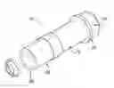
FIG. 1 is an isometric perspective view of a seal installation tool according to an embodiment of the disclosure.
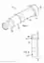
FIG. 2 is a side view of an embodiment of the disclosure.
FIG. 3 is a cross-sectional view of an embodiment of the disclosure.
FIG. 4 is a side view of an embodiment of the disclosure.
FIG. 5 is an in-use view of an embodiment of the disclosure.
DETAILED DESCRIPTION OF THE INVENTION
With reference now to the drawings, and in particular to FIGS. 1 through 5 thereof, a new seal installation tool embodying the principles and concepts of an embodiment of the disclosure and generally designated by the reference numeral 10 will be described.
As best illustrated in FIGS. 1 through 5, the seal installation tool 10 generally comprises a tube 12 that has a first end 14 and a second end 16. In one embodiment, the first end 14 is closed and the second end 16 is open. In another embodiment, the tube 12 comprises metal.
In yet another embodiment, the first end 14 is open and externally threaded. In this embodiment, the tool 10 comprises a cap 18 that is complementary to the first end 14 of the tube 12. The cap 18 comprises metal. The cap 18 is threadedly couplable to the first end 14 of the tube 12 such that the cap 18 is configured for impacting with an impactor. In still yet another embodiment, a lip 20 is coupled to a perimeter of the cap 18.
In one embodiment, each of a plurality of adaptors 22 has a first terminus 24 and a second terminus 26. The first termini 24 are configured to couple to the second end 16 of the tube 12. Each second terminus 26 has a circumference 28 that is complementary to a seal. The second terminus 26 is configured to reversibly couple to the seal. In another embodiment, the adaptors 22 comprise plastic. In yet another embodiment, the adaptors 22 comprise polyvinylchloride.
In one embodiment, a first coupler 30 is coupled to the tube 12 proximate to the second end 16. Each of a plurality of second couplers 32 is complementary to the first coupler 30. Each second coupler 32 is coupled proximate to the first terminus 24 of a respective adaptor 22. The first coupler 30 is positioned to selectively couple to a respective second coupler 32, such that a respective adaptor 22 is coupled to the tube 12. In another embodiment, the first coupler 30 comprises male threads 34.
In use, the first coupler 30 is positioned to selectively couple to a respective second coupler 32, such that a respective adaptor 22 is coupled to the tube 12. The second termini 26 are configured to reversibly couple to a seal, such as seals for transmissions and rear ends of a vehicle. The tube 12 is configured to position the seal at an installation site. The first end 14 is configured for impacting with an impactor to apply pressure evenly through the second end 16 to the seal. The seal is sealably coupled to the vehicle.
With respect to the above description then, it is to be realized that the optimum dimensional relationships for the parts of an embodiment enabled by the disclosure, to include variations in size, materials, shape, form, function and manner of operation, assembly and use, are deemed readily apparent and obvious to one skilled in the art, and all equivalent relationships to those illustrated in the drawings and described in the specification are intended to be encompassed by an embodiment of the disclosure.
Therefore, the foregoing is considered as illustrative only of the principles of the disclosure. Further, since numerous modifications and changes will readily occur to those skilled in the art, it is not desired to limit the disclosure to the exact construction and operation shown and described, and accordingly, all suitable modifications and equivalents may be resorted to, falling within the scope of the disclosure. In this patent document, the word “comprising” is used in its non-limiting sense to mean that items following the word are included, but items not specifically mentioned are not excluded. A reference to an element by the indefinite article “a” does not exclude the possibility that more than one of the element is present, unless the context clearly requires that there be only one of the elements.
Claims
I claim:1. A seal installation tool comprising:
a tube having a first end and a second end, said first end being closed, said second end being open; and
wherein said second end is sized such that said second end is configured for reversibly coupling to a seal, such as seals for transmissions and rear ends of a vehicle, such that said tube is configured for positioning the seal at an installation site, wherein said first end is configured for impacting with an impactor to apply pressure evenly through said second end to the seal, such that the seal is sealably coupled to the vehicle.
2. The tool of claim 1, further including said tube comprising metal.
3. The tool of claim 1, further comprising:
said first end being open, said first end being externally threaded;
a cap, said cap being complementary to said first end of said tube, said cap comprising metal; and
wherein said cap is threadedly couplable to said first end of said tube such that said cap is configured for impacting with an impactor.
4. The tool of claim 3, further including a lip, said lip being coupled to a perimeter of said cap.
5. The tool of claim 1, further including a plurality of adaptors, each said adaptor having a first terminus and a second terminus, said first terminus being configured for coupling to said second end of said tube, said second terminus having a circumference, said circumference being complementary to a seal, such that said second terminus is configured to reversibly couple to the seal.
6. The tool of claim 5, further including said adaptors comprising plastic.
7. The tool of claim 6, further including said adaptors comprising polyvinylchloride.
8. The tool of claim 5, further including comprising:
a first coupler coupled to said tube proximate to said second end;
a plurality of second couplers, said second couplers being complementary to said first coupler, each said second coupler being coupled proximate to said first terminus of a respective said adaptor; and
wherein said first coupler is positioned on said tube such that said first coupler is positioned for selective coupling to a respective said second coupler, such that a respective said adaptor is coupled to said tube.
9. The tool of claim 8, further including said first coupler comprising male threads.
10. A seal installation tool comprising:
a tube having a first end and a second end, said first end being closed, said second end being open, said tube comprising metal;
a plurality of adaptors, each said adaptor having a first terminus and a second terminus, said first terminus being configured for coupling to said second end of said tube, said second terminus having a circumference, said circumference being complementary to a seal, such that said second terminus is configured to reversibly couple to the seal, said adaptors comprising plastic, said adaptors comprising polyvinylchloride;
a first coupler coupled to said tube proximate to said second end, said first coupler comprising male threads;
a plurality of second couplers, said second couplers being complementary to said first coupler, each said second coupler being coupled proximate to said first terminus of a respective said adaptor, wherein said first coupler is positioned on said tube such that said first coupler is positioned for selective coupling to a respective said second coupler, such that a respective said adaptor is coupled to said tube; and
wherein said first coupler is positioned on said tube such that said first coupler is positioned for selective coupling to a respective said second coupler, such that a respective said adaptor is coupled to said tube; such that said second terminus is configured for reversibly coupling to a seal, such as seals for transmissions and rear ends of a vehicle, such that said tube is configured for positioning the seal at an installation site, wherein said first end is configured for impacting with an impactor to apply pressure evenly through said second end to the seal, such that the seal is sealably coupled to the vehicle.
11. The tool of claim 10, further comprising:
said first end being open, said first end being externally threaded;
a cap, said cap being complementary to said first end of said tube, said cap comprising metal;
a lip, said lip being coupled to a perimeter of said cap; and
wherein said cap is threadedly couplable to said first end of said tube such that said cap is configured for impacting with an impactor.
Images & Drawings included:


Sources:
- United States Patent and Trademark Office - verify current appl. status at the USPTO↗
Similar patent applications:
- » 20200406437
Seal installation tool - » 20210060745
SEAL INSTALLATION TOOL - » 20050125982
Seal installation tool and method - » 20140290020
RING SEAL INSTALLATION TOOL - » 20090229100
Seal installation tool - » 20070157764
Combined rear and front vehicle axle seal installation tool - » 20070186399
Seal installation tool - » 20130067710
Magnetic Pinion Shaft Seal Installation Tool - » 20080230999
Seal installation tool and method of using same - » 20210207490
Seal installation tool
Recent applications in this class:
- » 20250100116 2025-03-27
SEAL REMOVAL TOOL - » 20250010442 2025-01-09
Tool for Windshield Removal - » 20240399548 2024-12-05
APPARATUS FOR EXTRACTING PACKING - » 20240326206 2024-10-03
TOOL AND METHOD FOR REMOVING PACKING FROM THE FLUID END OF A PLUNGER PUMP - » 20240261947 2024-08-08
CALIBRATING TOOL - » 20240238951 2024-07-18
TOOL FOR REMOVING A SEAL RING FROM A SPARK PLUG - » 20230356374 2023-11-09
MOUNTING TOOL FOR POSITIONING A SHAFT SEALING RING ON A SHAFT AND METHOD FOR PRODUCING A SHAFT SEAL - » 20230321802 2023-10-12
Method and device for installing/removing a seal - » 20230117970 2023-04-20
INSERTION TOOL - » 20230066412 2023-03-02
Installation tool