Method and a system for determining a flow resistance across a particulate filter
US20180087431A1
2018-03-29
15/542,731
2016-01-18
✅ Patent granted
US 10,724,418 B2
2020-07-28
WO; PCT/SE2016/050026; 20160118
WO; WO2016/133443; 20160825
David A Rogers
Moore & Van Allen PLLC | W. Kevin Ransom
2036-05-27
Abstract:
A method of determining a flow resistance across a particulate filter located downstream of an internal combustion engine in an exhaust system. The method comprises measuring a first differential pressure across the particulate filter, measuring a second differential pressure downstream of the particulate filter, determining a pressure ratio of the first differential pressure and the second differential pressure, and from said pressure ratio, determining a flow resistance across the particulate filter. The second differential pressure is measured across a selective catalytic reduction system.
Inventors:
- Niklas KARPE 1 🇸🇪 Täby, Sweden
- Krister PETTERSON 1 🇸🇪 Katrineholm, Sweden
- Robert SVENSSON 1 🇸🇪 Gnesta, Sweden
- Krister Pettersson 1 🇸🇪 Katrineholm, Sweden
Assignee:
- SCANIA CV AB 382 🇸🇪 Södertälje, Sweden
Applicant:
Interested in similar patents?
Get notified when new applications in this technology area are published.
Classification:
F01N9/002 » CPC further
Electrical control of exhaust gas treating apparatus of filter regeneration, e.g. detection of clogging
F01N9/007 » CPC further
Electrical control of exhaust gas treating apparatus Storing data relevant to operation of exhaust systems for later retrieval and analysis, e.g. to research exhaust system malfunctions
F01N9/00 IPC
Electrical control of exhaust gas treating apparatus
F01N13/009 » CPC further
Exhaust or silencing apparatus characterised by constructional features ; Exhaust or silencing apparatus, or parts thereof, having pertinent characteristics not provided for in, or of interest apart from, groups - , , having two or more separate purifying devices arranged in series
F01N2560/07 » CPC further
Exhaust systems with means for detecting or measuring exhaust gas components or characteristics the means being an exhaust gas flow rate or velocity meter or sensor, intake flow meters only when exclusively used to determine exhaust gas parameters
F01N2560/08 » CPC further
Exhaust systems with means for detecting or measuring exhaust gas components or characteristics the means being a pressure sensor
F01N2900/0416 » CPC further
Details of electrical control or of the monitoring of the exhaust gas treating apparatus; Methods of control or diagnosing using the state of a sensor, e.g. of an exhaust gas sensor
F01N2900/1606 » CPC further
Details of electrical control or of the monitoring of the exhaust gas treating apparatus; Parameters used for exhaust control or diagnosing said parameters being related to the exhaust apparatus, e.g. particulate filter or catalyst Particle filter loading or soot amount
F01N3/20 IPC
Exhaust or silencing apparatus having means for purifying, rendering innocuous, or otherwise treating exhaust for rendering innocuous by thermal or catalytic conversion of noxious components of exhaust characterised by methods of operation; Control specially adapted for catalytic conversion ; Methods of operation or control of catalytic converters
F01N13/00 IPC
Exhaust or silencing apparatus characterised by constructional features ; Exhaust or silencing apparatus, or parts thereof, having pertinent characteristics not provided for in, or of interest apart from, groups - , ,
F01N11/002 » CPC main
Monitoring or diagnostic devices for exhaust-gas treatment apparatus, e.g. for catalytic activity the diagnostic devices measuring or estimating temperature or pressure in, or downstream of the exhaust apparatus
G01F1/34 » CPC further
Measuring the volume flow or mass flow of fluid or fluent solid material wherein the fluid passes through a meter in a continuous flow by using mechanical effects by measuring pressure or differential pressure
G01N15/0826 » CPC further
Investigating characteristics of particles; Investigating permeability, pore-volume, or surface-area of porous materials; Investigating permeability, pore-volume, or surface area of porous materials; Investigating permeability by forcing a fluid through a sample and measuring fluid flow rate, i.e. permeation rate or pressure change
G01N2015/084 » CPC further
Investigating characteristics of particles; Investigating permeability, pore-volume, or surface-area of porous materials; Investigating permeability, pore-volume, or surface area of porous materials Testing filters
G01N15/08 IPC
Investigating characteristics of particles; Investigating permeability, pore-volume, or surface-area of porous materials Investigating permeability, pore-volume, or surface area of porous materials
F01N3/035 » CPC further
Exhaust or silencing apparatus having means for purifying, rendering innocuous, or otherwise treating exhaust for cooling, or for removing solid constituents of, exhaust by means of filters in combination with other devices with catalytic reactors, e.g. catalysed diesel particulate filters
F01N3/2066 » CPC further
Exhaust or silencing apparatus having means for purifying, rendering innocuous, or otherwise treating exhaust for rendering innocuous by thermal or catalytic conversion of noxious components of exhaust characterised by methods of operation; Control specially adapted for catalytic conversion ; Methods of operation or control of catalytic converters Selective catalytic reduction [SCR]
F01N11/00 IPC
Monitoring or diagnostic devices for exhaust-gas treatment apparatus, e.g. for catalytic activity
F01N3/021 » CPC further
Exhaust or silencing apparatus having means for purifying, rendering innocuous, or otherwise treating exhaust for cooling, or for removing solid constituents of, exhaust by means of filters
Description
TECHNICAL FIELD
The invention relates to a method of determining a flow resistance across a particulate filter in an exhaust system according to the preamble of claim 1 and to a system for such determination according to the independent system claim. The invention also relates to a computer program, a computer program product, an electronic control unit and a motor vehicle.
BACKGROUND AND PRIOR ART
Internal combustion engines, and particularly diesel engines, produce a variety of different particles during combustion. The reason for this is mainly incomplete combustion of the fuel/air mixture and the type of particles produced vary depending on the fuel used and the type of engine. Since soot and other particles from internal combustion engines are generally harmful and contribute to the particulate matter pollution in the air, many jurisdictions apply increasingly strict emission regulations in order to minimize the emissions of particulate matter from internal combustion engines. One way of reducing the emissions is to fit a particulate filter in an exhaust system of the internal combustion engine. Such a filter may efficiently remove particulate matter from the exhaust gas of the engine. However, the filter becomes clogged with soot over time, such that the flow resistance across the filter increases. It is therefore common to regenerate the filter from time to time by increasing the temperature so that clogging soot particles are burnt off.
The necessity to regenerate the particulate filter may for example be determined by studying the flow resistance across the filter. The flow resistance is commonly given by combining the results of a pressure measurement across the filter and an estimation of the volume flow of exhaust gases through the filter. However, the volume flow of exhaust gases across the filter is difficult to estimate accurately due to leakage, temperature variations, evaporation, etc., and large flow variations over time due to e.g. varying throttle actuation and turbulent flows.
DE 4226055 discloses a method of determining a flow resistance across a particulate filter in an exhaust system, in which a first pressure sensing device is used to measure a first differential pressure across the particulate filter, and a second pressure sensing device is used to measure a second differential pressure across a cross-sectional reduction of the exhaust system downstream of the particulate filter. The first and the second differential pressures are used to determine a pressure ratio, which is compared to a threshold value. A filter regeneration is initiated if the difference between the threshold value and the pressure ratio is smaller than a predetermined setpoint.
However, a problem with the method as disclosed in DE 4226055 is that it requires a cross sectional reduction in the exhaust system across which the second differential pressure can be measured. Such a cross sectional reduction increases the flow resistance in the entire exhaust system and is therefore not desirable, since generally a low flow resistance of the system is needed to e.g. determine the flow resistance across the filter. Furthermore, a high flow resistance in the exhaust system may lead to increased fuel consumption.
SUMMARY OF THE INVENTION
It is an object of the present invention to overcome the above mentioned problem and provide a method and a system by means of which the flow resistance across a particulate filter may be determined without special arrangements, such as cross sectional reductions, in the exhaust system.
This object is, according to a first aspect of the present invention, achieved by the method as initially defined. The method is characterized in that the second differential pressure ΔP2 is measured across a selective catalytic reduction (SCR) system. An SCR system is used to reduce nitrogen oxide (NOx) emissions and is needed to comply with emission regulations in many jurisdictions. The inventive method is based on the realization that the pressure drop, or differential pressure, across the SCR system is of the same order as the pressure drop across the particulate filter. It is therefore possible to use the SCR system as a reference for determining the flow resistance of the particulate filter. The first differential pressure across the particulate filter gives an instant measure of the filter status, and the second differential pressure gives an instant estimate of the volume flow of exhaust gas through the exhaust system, since the flow resistance of the SCR system is reasonably constant over time.
According to one embodiment of the present invention, the first differential pressure and the second differential pressure are measured simultaneously. This enables an accurate determination of the flow resistance across the particulate filter. The simultaneous measurement of the first and the second differential pressure is also useful to find favorable circumstances with high volume flows through the exhaust system for determining the flow resistance across the particulate filter.
According to another embodiment of the present invention, the first differential pressure and the second differential pressure are measured using a single pressure sensing device. By using a single pressure sensing device, potential distortions affecting the pressure sensing device influence the measurement of the first differential pressure as well as the second differential pressure. Errors in the estimated volume flow in the exhaust system can thereby easily be compensated for.
According to another embodiment of the present invention, the method further includes the step:
-
- determining if a flow of exhaust gas through the exhaust system exceeds a predetermined threshold value,
wherein the step of determining a flow resistance is performed only when said threshold value is exceeded. The flow resistance can in this way be determined very accurately, since it is only determined under favorable circumstances.
- determining if a flow of exhaust gas through the exhaust system exceeds a predetermined threshold value,
According to another embodiment of the present invention, the second differential pressure is used in the step of determining if the flow of exhaust gas through the exhaust system exceeds a predetermined threshold value. This enables fast and accurate estimation of the volume flow of exhaust gas through the exhaust system.
According to another embodiment of the present invention, the determined flow resistance is tested against an error criterion, and, given that the error criterion is fulfilled, an error code is generated. The error criterion can e.g. be set so that error codes are generated if the flow resistance is such that it indicates either clogging of the particulate filter or cracks in the particulate filter. The error code can in this way be used to determine whether the filter needs to be regenerated, or if it necessary to change filters.
According to another embodiment of the present invention, the error criterion is fulfilled if the determined flow resistance exceeds a predetermined upper threshold value or falls below a predetermined lower threshold value. Using a threshold value is a simple and direct way of setting an error criterion.
According to another aspect of the present invention, the above mentioned object is fulfilled by a system as initially defined, which is characterized in that the pressure sensing means for determining a second differential pressure is configured to measure the second differential pressure across a selective catalytic reduction system. The advantages of such a system as well as preferred embodiments thereof are apparent from the above discussion relating to the proposed method.
According to one embodiment of this second aspect of the invention, the pressure sensing means comprises a single pressure sensing device configured to measure the first differential pressure and the second differential pressure.
In other aspects, the invention also relates to a computer program having the features of claim 10, a computer program product having the features of claim 11, an electronic control unit having the features of claim 12 and a motor vehicle according to claims 13 and 14.
Other advantageous features as well as advantages of the present invention will appear from the following description.
BRIEF DESCRIPTION OF THE DRAWINGS
The invention will in the following be further described by means of example with reference to the appended drawings, wherein
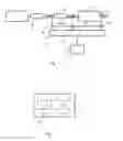
FIG. 1 shows a schematic drawing of an exhaust system including a system according to an embodiment of the invention,
FIG. 2 shows a flow chart of a method according to an embodiment of the invention, and
FIG. 3 shows a schematic drawing of a control unit for implementing a method according to the invention.
DETAILED DESCRIPTION OF EMBODIMENTS OF THE INVENTION
An exhaust system of an internal combustion engine 1 in a motor vehicle is schematically shown in FIG. 1. The exhaust system comprises a diesel oxidation catalyst unit 2, a particulate filter 3 located downstream of the oxidation catalyst unit 2, and further a selective catalytic reduction (SCR) system 4 downstream of the particulate filter 3. The exhaust system further comprises pressure sensing means in the form of a differential pressure sensor 5. The differential pressure sensor 5 is configured to simultaneously measure a first differential pressure ΔP1 across the particulate filter 3 and a second differential pressure ΔP2 across the SCR system 4. For this purpose, the pressure sensor 5 has pressure inlet ports 8, 9, 10 located upstream the particulate filter 3, between the particulate filter 3 and the SCR system 4, and downstream the SCR system 4, respectively. Processing means in the form of a processing unit 6 is connected to the differential pressure sensor 5. The processing unit 6 is configured to calculate a pressure ratio ΔP1/ΔP2 and, based on said pressure ratio, a flow resistance R across the particulate filter 3, which is related to the pressure ratio as R=k·ΔP1/ΔP2, wherein k is a constant. During operation of the internal combustion engine 1, exhaust gases are generated and follow the direction of the arrows through exhaust system before being emitted through an exhaust pipe 7.
The flow chart in FIG. 2 illustrates a method according to an embodiment of the invention. Using the differential pressure sensor 5, the first differential pressure ΔP1 across the particulate filter 3 and the second differential pressure Δ P2 across the SCR system 4 are measured simultaneously in a step S1. In a step S2, it is checked whether the volume flow φ of exhaust gas through the exhaust system exceeds a predetermined threshold value φT. This determination is performed using the second differential pressure ΔP2 across the SCR system 4, which is proportional to the flow φ. If it is determined that the flow φ exceeds the predetermined threshold value φT, the pressure ratio ΔP1/ΔP2 is determined in a step S3 using the processing unit. From the pressure ratio ΔP1/ΔP2, the flow resistance R across the particulate filter 3 is calculated in a step S4.
If the flow φ of exhaust gas is lower than the predetermined threshold value φT, no determination of the pressure ratio ΔP1/ΔP2 is carried out until the flow exceeds the threshold value.
Once the flow resistance R across the particulate filter 3 has been calculated, it may be tested against a preset error criterion in a step S5. Given that the error criterion is fulfilled, an error code is generated in a step S6. The error criterion may be set such that it is fulfilled if the determined flow resistance R exceeds a predetermined upper threshold value RU, indicating that the particulate filter 3 is clogged, or falls below a predetermined lower threshold value RL, indicating that there are e.g. cracks in the particulate filter 3. Different error codes are generated depending on the outcome of the testing against the error criterion. The error code may in case of a clogged particular filter 3 e.g. trigger a regeneration process, or in the case of a cracked filter trigger generation of an alarm signal, alerting a driver of a vehicle in which the exhaust system is located that the particulate filter 3 needs to be changed. Data relating to the flow resistance may also be saved in a database for later reference.
The system according to the invention may also comprise separate pressure sensing devices for sensing the differential pressures ΔP1 and ΔP2, respectively. The pressure sensing means may comprise any kind of known pressure sensing device suitable for measuring differential pressures under the conditions applicable in exhaust systems. It is preferable, but not necessary, that the measurements of the differential pressures ΔP1 and ΔP2 are performed simultaneously, since this ensures that the conditions under which the flow resistance R is determined are equivalent to those under which the volume flow φ of exhaust gas is determined. The pressure sensing device used to determine the second differential ΔP2 in the shown embodiment has pressure inlet ports 9, 10 located upstream and downstream the SCR system 4. However, the pressure inlet port located downstream the SCR system 4 may be substituted for an atmospheric pressure inlet port.
FIG. 3 illustrates very schematically an electronic control unit 11 comprising an execution means 12, such as a central processor unit (CPU), for executing a computer program. The execution means 12 communicates with a memory 13, for example of the type RAM, through a data bus 14. The control unit 11 also comprises a non-transitory data storing medium 15, for example in the form of a Flash memory or a memory of the type ROM, PROM, EPROM or EEPROM. The execution means 12 communicates with the data storing medium 15 through the data bus 14. A computer program comprising computer program code for implementing a method according to the invention is stored on the data storing medium 15.
The invention is of course not in any way restricted to the embodiments described above. On the contrary, many possibilities to modifications thereof will be apparent to a person with ordinary skill in the art without departing from the basic idea of the invention such as defined in the appended claims.
Claims
1. A method of determining a flow resistance across a particulate filter in an exhaust system, which particulate filter is located downstream of an internal combustion engine, the method comprising:
measuring a first differential pressure across the particulate filter;
measuring a second differential pressure downstream of the particulate filter across a selective catalytic reduction system;
determining a pressure ratio of the first differential pressure and the second differential pressure;
determining if a flow of exhaust gas through the exhaust system exceeds a predetermined threshold value; and
when said threshold value is exceeded, determining from said pressure ratio, a flow resistance across the particulate filter.
2. The method according to claim 1, wherein the first differential pressure and the second differential pressure are measured simultaneously.
3. The method according to claim 2, wherein the first differential pressure and the second differential pressure are measured using a single pressure sensing device.
4. (canceled)
5. The method according to claim 4, wherein the second differential pressure is used in the step of determining if the flow of exhaust gas through the exhaust system exceeds a predetermined threshold value.
6. The method according to claim 1, wherein the determined flow resistance is tested against an error criterion, and, given that the error criterion is fulfilled, an error code is generated.
7. The method according to claim 6, wherein the error criterion is fulfilled if the determined flow resistance exceeds a predetermined upper threshold value or falls below a predetermined lower threshold value.
8. A system for determining a flow resistance across a particulate filter in an exhaust system, which particulate filter is located downstream of an internal combustion engine, the system comprising:
pressure sensing means for determining a first differential pressure across the particulate filter and a second differential pressure downstream of the particulate filter across a selective catalytic reduction system;
processing means configured to determine a pressure ratio of the first differential pressure and the second differential pressure;
processing means configured to determine if a flow of exhaust gas through the exhaust system exceeds a predetermined threshold value; and
processing means configured to determine a flow resistance only when said predetermined threshold value is exceeded.
9. The system according to claim 8, wherein the pressure sensing means comprises a single pressure sensing device configured to measure the first differential pressure and the second differential pressure.
10. A computer program product comprising computer program code stored in a non-transitory computer-readable medium readable by a computer, said computer program product used for determining a flow resistance across a particulate filter in an exhaust system, which particulate filter is located downstream of an internal combustion engine, wherein said computer program code comprising computer instructions to cause one or more computer processors to perform the following operations:
measuring a first differential pressure across the particulate filter;
measuring a second differential pressure downstream of the particulate filter across a selective catalytic reduction system;
determining a pressure ratio of the first differential pressure and the second differential pressure;
determining if a flow of exhaust gas through the exhaust system exceeds a predetermined threshold value; and
when said threshold value is exceeded, determining from said pressure ratio, a flow resistance across the particulate filter.
11. (canceled)
12. An electronic control unit of a motor vehicle comprising:
an execution means;
a memory connected to the execution means;
a data storage medium which is connected to the execution means; and
computer program product comprising computer program code stored in a non-transitory computer-readable medium readable by a computer, said computer program product used for determining a flow resistance across a particulate filter in an exhaust system, which particulate filter is located downstream of an internal combustion engine, wherein said computer program code comprising computer instructions to cause one or more computer processors to perform the following operations:
measuring a first differential pressure across the particulate filter;
measuring a second differential pressure downstream of the particulate filter across a selective catalytic reduction system;
determining a pressure ratio of the first differential pressure and the second differential pressure;
determining if a flow of exhaust gas through the exhaust system exceeds a predetermined threshold value; and
when said threshold value is exceeded, determining from said pressure ratio, a flow resistance across the particulate filter.
13. A motor vehicle comprising an electronic control unit, wherein said electronic control unit comprises:
an execution means;
a memory connected to the execution means;
a data storage medium which is connected to the execution means; and
computer program product comprising computer program code stored in a non-transitory computer-readable medium readable by a computer, said computer program product used for determining a flow resistance across a particulate filter in an exhaust system, which particulate filter is located downstream of an internal combustion engine, wherein said computer program code comprising computer instructions to cause one or more computer processors to perform the following operations:
measuring a first differential pressure across the particulate filter;
measuring a second differential pressure downstream of the particulate filter across a selective catalytic reduction system;
determining a pressure ratio of the first differential pressure and the second differential pressure;
determining if a flow of exhaust gas through the exhaust system exceeds a predetermined threshold value; and
when said threshold value is exceeded, determining from said pressure ratio, a flow resistance across the particulate filter.
14. A motor vehicle according to claim 13, wherein the motor vehicle is a truck or a bus.
Images & Drawings included:


Sources:
- United States Patent and Trademark Office - verify current appl. status at the USPTO↗
Recent applications in this class:
- » 20250264049 2025-08-21
METHOD FOR DETECTING EXHAUST BACKFLOW IN AN INTERNAL COMBUSTION ENGINE - » 20250092813 2025-03-20
METHOD FOR ASCERTAINING AN OPERATING STATE OF A BURNER - » 20250043711 2025-02-06
DIESEL ENGINE AFTERTREATMENT SYSTEM - » 20240392716 2024-11-28
COMPUTER-IMPLEMENTED METHOD FOR DETECTING A FAULT IN A SELECTIVE CATALYTIC REDUCER ASSEMBLY - » 20240318585 2024-09-26
SYSTEMS AND METHODS FOR DIAGNOSING COMPONENT FAILURE - » 20240295185 2024-09-05
SYSTEMS AND METHODS FOR EXHAUST AFTERTREATMENT SENSOR OFFSET DETECTION AND DIAGNOSIS - » 20240254909 2024-08-01
VEHICLE EMISSIONS MANAGEMENT - » 20240191646 2024-06-13
METHOD AND DEVICE FOR DIAGNOSING AN AIR SUPPLY OF AN INTERNAL COMBUSTION ENGINE - » 20240183303 2024-06-06
System and method for monitoring an oxidation catalyst - » 20240093625 2024-03-21
Method for operating a particle filter taking the ash quantity into consideration
Recent applications for this Assignee:
- » 20250289437 2025-09-18
METHOD AND SENSOR ARRANGEMENT FOR DETERMINING AN ADVERSE CONDITION OF A POWERTRAIN - » 20250276701 2025-09-04
CONTROL DEVICE AND METHOD FOR ESTIMATING DRIVING RANGE FOR A VEHICLE - » 20250269735 2025-08-28
METHOD OF CONTROLLING RETARDATION OF A VEHICLE, COMPUTER PROGRAM, COMPUTER-READABLE MEDIUM, CONTROL ARRANGEMENT, AND VEHICLE - » 20250264080 2025-08-21
FUEL INJECTOR INTERNAL COMBUSTION ENGINE AND VEHICLE - » 20250257797 2025-08-14
CONTROL ARRANGEMENT AND METHOD FOR CONTROLLING A POWERTRAIN OF A VEHICLE - » 20250229785 2025-07-17
METHOD OF CONTROLLING OPERATION OF A VEHICLE, COMPUTER PROGRAM, COMPUTER-READABLE MEDIUM, CONTROL ARRANGEMENT, AND VEHICLE - » 20250222929 2025-07-10
METHOD OF CONTROLLING OPERATION OF A VEHICLE, COMPUTER PROGRAM, COMPUTER-READABLE MEDIUM, CONTROL ARRANGEMENT, AND VEHICLE - » 20250210776 2025-06-26
BATTERY PACK AND A VEHICLE COMPRISING A BATTERY PACK - » 20250206173 2025-06-26
CONTROL DEVICE AND METHOD FOR CONTROLLING CHARGING OF AN ENERGY STORAGE DEVICE - » 20250191868 2025-06-12
BUS BAR CURRENT INTERRUPTION DEVICE AND ENERGY STORAGE DEVICE