Phase alignment device
US20180104791A1
2018-04-19
15/017,643
2016-02-07
✅ Patent granted
US 9,943,944 B1
2018-04-17
-
-
R. A. Smith
2036-02-07
Abstract:
The phase alignment device to be used with a phase alignment tool may include a body section; and a driving head section connected to the body section. The body section and the driving head section may include an aperture which extends through the body section and the driving head section.
Applicant:
Interested in similar patents?
Get notified when new applications in this technology area are published.
Classification:
G01B5/25 » CPC further
Measuring arrangements characterised by the use of mechanical means for measuring angles or tapers; for testing the alignment of axes for testing the alignment of axes
B25B27/16 » CPC further
Hand tools, specially adapted for fitting together or separating parts or objects whether or not involving some deformation, not otherwise provided for for assembling objects other than by press fit or detaching same abutted flanges
F16D1/12 » CPC further
Couplings for rigidly connecting two coaxial shafts or other movable machine elements allowing adjustment of the parts about the axis
F01D5/026 » CPC further
Blades; Blade-carrying members ; Heating, heat-insulating, cooling or antivibration means on the blades or the members; Blade-carrying members, e.g. rotors Shaft to shaft connections
F01D5/02 IPC
Blades; Blade-carrying members ; Heating, heat-insulating, cooling or antivibration means on the blades or the members Blade-carrying members, e.g. rotors
G01B11/26 » CPC further
Measuring arrangements characterised by the use of optical means for measuring angles or tapers; for testing the alignment of axes
F16D1/033 » CPC further
Couplings for rigidly connecting two coaxial shafts or other movable machine elements for connecting two abutting shafts or the like by clamping together two faces perpendicular to the axis of rotation, e.g. with bolted flanges
B24B47/04 » CPC main
Drives or gearings; Equipment therefor for performing a reciprocating movement of carriages or work- tables by mechanical gearing only
Description
FIELD OF THE INVENTION
The present invention relates to a phase alignment device which may be used with a phase alignment tool.
BACKGROUND
Summary
The phase alignment device to be used with a phase alignment tool may include a body section; and a driving head section connected to the body section. The body section and the driving head section may include an aperture which extends through the body section and the driving head section.
The phase alignment device to be used with a phase alignment may include the body section being cylinder shaped.
The phase alignment device to be used with a phase alignment may include the driving head section being hexagon shaped.
The phase alignment device to be used with a phase alignment may include the body section being thread free.
BRIEF DESCRIPTION OF THE DRAWINGS
The invention may be understood by reference to the following description taken in conjunction with the accompanying drawings, in which, like reference numerals identify like elements, and in which:
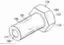
FIG. 1 illustrates a back perspective view of the phase alignment device of the present invention;
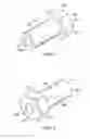
FIG. 2 illustrates a front perspective view of the phase alignment device of the present invention;
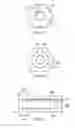
FIG. 3 illustrates a front view of the phase alignment device of the present invention;
FIG. 4 illustrates a back view of the phase alignment device of the present invention;
FIG. 5 illustrates a cross-sectional side view of the phase alignment device of the present invention;
DETAILED DESCRIPTION
FIG. 1 illustrates a back perspective view of the phase alignment device 100 of the present invention and illustrates a body section 101 and a driving head section 103 which may be integrally connected to the body section 101. The body section 101 and the driving head section 103 may be formed from the same material which may be metal including steel, wood, plastic or other appropriate material. The body section 101 may include an outer peripheral surface 105 and an opposing inner peripheral surface 107 which may define a central aperture 109 which may extend through the phase alignment device 100 to cooperate with a shaft (not shown).
The body section 101 may include a bottom surface 111 which may connect the outer peripheral surface 105 with the inner peripheral surface 107.
The driving head section 103 may be a hexagon shaped and may include a plurality of driving surfaces 113 which may extend around the periphery of the driving head section 103 and may include a top surface 115 which may connect the driving surfaces 113 and the central aperture 109 may extend through the top surface 115.
FIG. 2 illustrates a front perspective view of the phase alignment device 100 of the present invention and illustrates a body section 101 and a driving head section 103 which may be integrally connected to the body section 101. The body section 101 and the driving head section 103 may be formed from the same material which may be metal including steel, wood, plastic or other appropriate material. The body section 101 may include an outer peripheral surface 105 and an opposing inner peripheral surface 107 which may define a central aperture 109 which may extend through the phase alignment device 100 to cooperate with a shaft (not shown).
The body section 101 may include a bottom surface 111 which may connect the outer peripheral surface 105 with the inner peripheral surface 107.
The driving head section 103 may be a hexagon shaped and may include a plurality of driving surfaces 113 which may extend around the periphery of the driving head section 103 and may include a top surface 115 which may connect the driving surfaces 113 and the central aperture 109 may extend through the top surface 115.
FIG. 5 illustrates a cross-sectional the view of the phase alignment device 100 of the present invention and illustrates a body section 101 and a driving head section 103 which may be integrally connected to the body section 101. The body section 101 and the driving head section 103 may be formed from the same material which may be metal including steel, wood, plastic or other appropriate material. The body section 101 may include an outer peripheral surface 105 and an opposing inner peripheral surface 107 which may define a central aperture 109 which may extend through the phase alignment device 100 to cooperate with a shaft (not shown).
The body section 101 may include a bottom surface 111 which may connect the outer peripheral surface 105 with the inner peripheral surface 107.
The driving head section 103 may be a hexagon shaped and may include a plurality of driving surfaces 113 which may extend around the periphery of the driving head section 103 and may include a top surface 115 which may connect the driving surfaces 113 and the central aperture 109 may extend through the top surface 115.
FIG. 4 illustrates a bottom view of the body section 101 and illustrates the bottom surface 111, the central aperture 109, the outer peripheral surface 105 and the inner peripheral surface 107.
FIG. 3 illustrates a top view of the driving head section 103 and illustrates the top surface 115, the driving surface 113 and the central aperture 109.
While the invention is susceptible to various modifications and alternative forms, specific embodiments thereof have been shown by way of example in the drawings and are herein described in detail. It should be understood, however, that the description herein of specific embodiments is not intended to limit the invention to the particular forms disclosed.
Claims
1) The phase alignment device to be used with a phase alignment tool, comprising;
a body section;
a driving head section connected to the body section; and wherein the body section and the driving head section includes an aperture which extends through the body section and the driving head section.
2) The phase alignment device to be used with a phase alignment tool as in claim 1, wherein the body section is cylinder shaped.
3) The phase alignment device to be used with a phase alignment tool as in claim 1, wherein the driving head section is hexagon shaped.
4) The phase alignment device to be used with a phase alignment tool as in claim 1, wherein the body section is thread free.
Images & Drawings included:
Sources:
- United States Patent and Trademark Office - verify current appl. status at the USPTO↗
Similar patent applications:
- » 20060154790
Forming phase alignment device in formed sheet manufacturing apparatus - » 20240214177
MULTI-DEVICE SYSTEM AND METHOD FOR PHASE ALIGNMENT OF DEVICES IN THE MULTI-DEVICE SYSTEM - » 20230001734
Micro-optic security device with phase aligned image layers - » 20240253385
MICRO-OPTIC SECURITY DEVICE WITH PHASE ALIGNED IMAGE LAYERS - » 20170250695
Method and device to align phases of clock signals - » 20190123454
Polymer dispersed/shear aligned phase modulator device - » 20150280115
Double self-aligned phase change memory device structure - » 20240205850
ELECTRONIC DEVICE AND METHOD FOR PHASE ALIGNMENT - » 20150322346
Polymer composition having photoalignable group, liquid crystal alignment film formed of the polymer composition, and optical device having phase difference plate formed of the liquid crystal alignment film - » 20130331482
POLYMER COMPOSITION HAVING PHOTOALIGNABLE GROUP, LIQUID CRYSTAL ALIGNMENT FILM FORMED OF THE POLYMER COMPOSITION, AND OPTICAL DEVICE HAVING PHASE DIFFERENCE PLATE FORMED OF THE LIQUID CRYSTAL ALIGNMENT FILM
Recent applications in this class:
- » 20110070812 2011-03-24
CIRCULAR PATH GENERATING DEVICE