Fin and micro-channel heat exchanger
US20180106549A1
2018-04-19
15/782,813
2017-10-12
✅ Patent granted
US 10,415,887 B2
2019-09-17
-
-
Raheena R Malik
2037-10-12
Abstract:
The present invention discloses a fin and a micro-channel heat exchanger. A retractable fin in a bending region of the micro-channel heat exchanger comprises a plurality of fin unit sections which are sequentially connected to form a corrugated structure, each fin unit section comprises a first straight section and an arc top section, and a retractable section which is deformed due to stretching/squeezing in a bending process of the micro-channel heat exchanger is provided between the first straight section and the arc top section. The retractable sections of the retractable fin are gradually straightened in the bending process of the micro-channel heat exchanger, included angles between the retractable sections and adjacent straight sections gradually become small, and this thereby ensures that the retractable fin in the bending region is not stretch-broken.
Inventors:
- Feng Wang 15 🇨🇳 Hangzhou, China
- Huazhao Liu 9 🇨🇳 Hangzhou, China
- Feng Wang 10 🇨🇳 Zhejiang, China
- Huazhao Liu 2 🇨🇳 Zhejiang, China
Assignee:
- DUNAN ENVIRONMENT TECHNOLOGY CO., LTD 2 🇨🇳 Hangzhou, China
Applicant:
Interested in similar patents?
Get notified when new applications in this technology area are published.
Classification:
F28D1/05366 » CPC main
Heat-exchange apparatus having stationary conduit assemblies for one heat-exchange medium only, the media being in contact with different sides of the conduit wall, in which the other heat-exchange medium is a large body of fluid, e.g. domestic or motor car radiators with heat-exchange conduits immersed in the body of fluid with tubular conduits the conduits being straight the conduits having a non-circular cross-section Assemblies of conduits connected to common headers, e.g. core type radiators
F28F9/0212 » CPC further
Casings; Header boxes; Auxiliary supports for elements; Auxiliary members within casings; Header boxes; End plates; Header boxes having their inner space divided by partitions for elongated header box, e.g. with transversal and longitudinal partitions having only transversal partitions the partitions being separate elements attached to header boxes
F28F17/005 » CPC further
Removing ice or water from heat-exchange apparatus Means for draining condensates from heat exchangers, e.g. from evaporators
F28D1/053 IPC
Heat-exchange apparatus having stationary conduit assemblies for one heat-exchange medium only, the media being in contact with different sides of the conduit wall, in which the other heat-exchange medium is a large body of fluid, e.g. domestic or motor car radiators with heat-exchange conduits immersed in the body of fluid with tubular conduits the conduits being straight
F28F9/02 IPC
Casings; Header boxes; Auxiliary supports for elements; Auxiliary members within casings Header boxes; End plates
F28F1/126 » CPC further
Tubular elements; Assemblies of tubular elements; Tubular elements and assemblies thereof with means for increasing heat-transfer area, e.g. with fins, with projections, with recesses the means being only outside the tubular element consisting of zig-zag shaped fins
F28D2021/007 » CPC further
Heat-exchange apparatus not covered by any of the groups - ; Other heat exchangers for particular applications; Heat exchange systems not otherwise provided for for refrigerant cycles Condensers
F28D2021/0071 » CPC further
Heat-exchange apparatus not covered by any of the groups - ; Other heat exchangers for particular applications; Heat exchange systems not otherwise provided for for refrigerant cycles Evaporators
F28F2009/0292 » CPC further
Casings; Header boxes; Auxiliary supports for elements; Auxiliary members within casings; Header boxes; End plates; Other particular headers or end plates with fins
F28F1/12 IPC
Tubular elements; Assemblies of tubular elements; Tubular elements and assemblies thereof with means for increasing heat-transfer area, e.g. with fins, with projections, with recesses the means being only outside the tubular element
F28D21/00 IPC
Heat-exchange apparatus not covered by any of the groups -
F28F17/00 IPC
Removing ice or water from heat-exchange apparatus
F28D1/02 IPC
Heat-exchange apparatus having stationary conduit assemblies for one heat-exchange medium only, the media being in contact with different sides of the conduit wall, in which the other heat-exchange medium is a large body of fluid, e.g. domestic or motor car radiators with heat-exchange conduits immersed in the body of fluid
F28D2001/0273 » CPC further
Heat-exchange apparatus having stationary conduit assemblies for one heat-exchange medium only, the media being in contact with different sides of the conduit wall, in which the other heat-exchange medium is a large body of fluid, e.g. domestic or motor car radiators with heat-exchange conduits immersed in the body of fluid; Particular components; Cores having special shape, e.g. curved, annular
Description
CROSS REFERENCE TO RELATED APPLICATIONS
The present application claims the benefit of Chinese Patent Application No. 201610905058.X filed on Oct. 17, 2016. All the above are hereby incorporated by reference.
FIELD OF THE INVENTION
The present invention relates to an air conditioning technique, in particular to a heat exchanger.
FIELD OF THE INVENTION
A micro-channel heat exchanger consists of header pipes, micro-channel flat pipes and fins, and has the advantages such as light weight, compact structure, high heat exchange efficiency, all-aluminum structure and convenience in recovery, and the like; and at the same time, an internal volume of the micro-channel heat exchanger is small, the filling amount of refrigerant is greatly reduced, the industrial trend of energy saving and environmental protection is satisfied and thus the micro-channel heat exchanger is widely applied to commercial/domestic air conditioner fields.
In order to obtain corresponding heat exchange amount and energy-efficiency ratio in a limited unit space, an evaporator and a condenser in an air conditioner often need to be bent to a certain angle to increase a heat exchange area, so as to satisfy the performance requirement during air conditioner design. Commonly seen bent shapes generally include an L-shape, a C-shape, a U-shape and the like. Air conditioning units in the current market are mostly heat-pump air conditioners which consider refrigeration and heating at the same time. In order to satisfy the demands of air conditioning units for drainage performance during operation in winter, the micro-channel heat exchange is generally designed in such a way that the header pipes are horizontally disposed, and the flat pipes and the fins are vertically disposed. Therefore, the micro-channel heat exchanger needs to be bent along a length direction of the header pipes to form a structure having a designated angle. In a bending process of a traditional micro-channel heat exchanger, fins on an inner side of a bend are squeezed, deformation such as inverted fins and distortion and the like occurs and the circulation of air is thereby obstructed; and fins on an outer side of the bend are stretched, situations such as stretching deformation and even tearing and the like occur, the appearance of the heat exchanger is seriously influenced, and at the same time, since the fins are torn, the heat exchange performance of the heat exchange is decreased.
Therefore, how to decrease the influence of bending on the performance of the micro-channel heat exchanger when the micro-channel heat exchange is bent along a direction towards the header pipes is an important problem which needs to be solved in this field.
SUMMARY OF THE INVENTION
The technical problem to be solved by the present invention is to provide a fin and a micro-channel heat exchanger, so as to decrease the influence of bending on the performance of the micro-channel heat exchanger when the micro-channel heat exchanger is bent along a direction towards header pipes.
In order to solve the above-mentioned technical problem, the present invention adopts the following technical solution: a fin comprises a plurality of fin unit sections which are sequentially connected to form a corrugated structure, each fin unit section comprises a first straight section and an arc top section, and a retractable section which is deformed due to stretching/squeezing in a bending process of the micro-channel heat exchanger is provided between the first straight section and the arc top section.
Preferably, the retractable section is of an arc concave structure.
Preferably, a second straight section between the arc top section and the retractable section is further provided.
Preferably, along an extension direction of the fin, a minimum spacing between adjacent first straight sections is L, a maximum spacing between adjacent second straight sections is L1, and L is greater than L1.
Preferably, the fin unit section on an outer side of a bend consists of three parts, i.e., an arc top section, a straight section and a retractable section, and the fin unit section on an inner side of the bend consists of an arc top section and a straight section.
Preferably, a length and an angle of the retractable section on the inner side of the bend are smaller than a length and an angle of the retractable section on the outer side of the bend.
Preferably, a width of the fin is greater than or equal to a width of a flat pipe.
Preferably, the first straight section is provided with a louver structure used for enhancing heat exchange.
The present invention further provides a micro-channel heat exchanger, comprising flat plate regions and a bending region which is bent between two adjacent flat plate regions, wherein the bending region is provided with the above-mentioned fin.
Further, a fin provided in the flat plate region comprises straight sections and arc top sections which are connected with the straight sections, and the straight sections are provided with louver structures used for enhancing heat exchange.
In the technical solution adopted by the present invention, a retractable fin is provided in a corresponding bending region in the bending process of the micro-channel heat exchanger, retractable sections of the retractable fin are gradually straightened in the bending process of the micro-channel heat exchanger, included angles between the retractable sections and adjacent straight sections gradually become small, and this thereby ensures that the retractable fin in the bending region is not stretch-broken.
Therefore, the present invention well solves the problem of fin deformation caused when the heat exchanger is bent along the length direction of the header pipes, and can guarantee the performance and appearance of the heat exchanger as good as possible.
DESCRIPTION OF THE DRAWINGS
The present invention will be further described below in combination with the drawings and the embodiments.
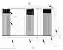
FIG. 1 is an overall structural view of a micro-channel heat exchanger;
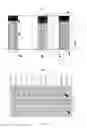
FIG. 2 is a schematic view of fins in a flat plate region and arrangement;
FIG. 3 is a partial view of fins and flat pipes in a flat plate region;
FIG. 4 is a structural schematic view of a common fin;
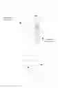
FIG. 5 is a schematic view of fins in a bending region and arrangement;
FIG. 6 illustrates a partial view of fins and flat pipes in a bending region;
FIG. 7 is a structural schematic view of a retractable fin;
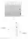
FIG. 8 is a comparison view of a retractable fin before and after bending;
FIG. 9 is a structural view of a retractable fin in Embodiment 1; and
FIG. 10 is a structural view of a retractable fin in Embodiment 2.
DESCRIPTION OF THE EMBODIMENTS
Embodiment 1
as illustrated in FIG. 1, a micro-channel heat exchanger comprises header pipes 2, flat pipes 21 and fins, the flat pipes 21 are connected to the header pipes 2, the fins are installed between adjacent flat pipes, and end portions of the header pipes are connected with connecting pipes 22. The micro-channel heat exchanger is divided into a bending region 10 and flat plate regions 11 along a length direction of the header pipes 2, the bending region 10 is a region of the micro-channel heat exchanger for bending in a bending process, and the flat plate regions adopt common fins 110.
In view of the fact that fins on an inner side of a bend are squeezed in a bending process of a traditional micro-channel heat exchanger, deformation such as inverted fins and distortion and the like occurs and the circulation of air is thereby obstructed; and that fins on an outer side of the bend are stretched and situations such as stretching deformation and even tearing and the like occur, the bending region 10 adopts specially designed retractable fins 100.
Herein, the common fins 110 and the retractable fins 100 are all corrugated fins. Each of the common fins 110 and the retractable fins 100 comprises a plurality of fin unit sections which are sequentially connected to form a corrugated structure.
As illustrated in FIG. 2 to FIG. 4, each common fin 110 provided in the flat plate region 11 comprises straight sections 111 and arc top sections 112 which are connected with the straight sections 111, and the straight sections 111 are provided with louver structures used for enhancing heat exchange.
As illustrated in FIG. 5 to FIG. 7, in the retractable fins 100 provided in the bending region 10, the fin unit section comprises a first straight section 101 and an arc top section 104, and a retractable section 102 which is deformed due to stretching/squeezing in a bending process of the micro-channel heat exchanger is provided between the first straight section 101 and the arc top section 104. Further, a second straight section 103 between the arc top section and the retractable section is further provided.
As illustrated in FIG. 8, in the structure of the retractable fin 100, a minimum spacing between adjacent first straight sections 101 is L, a maximum spacing between adjacent second straight sections 103 is L1, and as compared with an equal spacing of the common fin 110, the spacing L of the retractable fin 100 is far greater than the spacing L1. By comparing the retractable fin in the bending region before and after bending, when the micro-channel heat exchanger is bent, the bending region is stressed and bent from a flat plate state to a curved surface having a certain radian, at this moment an arc length of an outer side of the bending region is greater than an arc length of an inner side of the bending region, at this moment the outer side of the bending region is stressed and stretched, and the inner side of the bending region is squeezed. Consequently, the retractable fin at a position close to an outer side of the bend in the bending region is stretched and deformed, and the retractable fin at a position close to an inner side in the bending region is squeezed and deformed. Since transition between the first straight section 101 and the second straight section 103 of the retractable fin is realized through the retractable section 102, in the bending process of the micro-channel heat exchanger, the retractable sections of the retractable fin are gradually straightened, included angles between the retractable sections and the straight sections gradually become small, at this moment a difference between L1 and L continuously decreases, an arc top of the retractable fin close to the outer side of the bend is elongated a distance L2 after the bending of the micro-channel heat exchanger is completed, and this thereby ensures that the retractable fin in the bending region is not stretch-broken.
Of course, as illustrated in FIG. 9, the structure of the second straight sections may not be provided, and only the retractable sections 102 are provided between the first straight sections 101 and the arc top sections 104.
In addition, it needs to be noted that the length and angle of the retractable sections of the retractable fin 100 on the inner side of the bend and the outer side of the bend may be respectively different. The width of the retractable fin and the width of the flat pipe may be different. Preferably, the length and angle of the retractable section on the inner side of the bend are smaller than the length and angle of the retractable section on the outer side of the bend, because the retractable fin 100 on the outer side of the bend is a major deforming position. Besides, the width of the retractable fin 100 is greater than or equal to the width of the flat pipe 21.
Embodiment 2
as illustrated in FIG. 10, an overall structure of a retractable fin 100 is divided into two parts, one part is an outer side of a bending region and the other part is an inner side of the bending region, wherein a fin unit section on the outer side of the bending region consists of three parts, i.e., an arc top section 104, a straight section 101 and a retractable section 102 between the arc top section 104 and the straight section 101, a fin unit section on the inner side of the bending region consists of two parts, i.e., the arc top section 104 and the straight section 101, and the straight section is provided with a louver structure used for enhancing heat exchange. The retractable section 102 is provided because the retractable fin 100 on the outer side of the bending region is a major deforming position.
Moreover, a partition seam may be provided between the outer side of the bending region and the inner side of the bending region of the retractable fin 100, and seamless connection may also be adopted on the whole.
Claims
1. A fin, wherein the fin comprises a plurality of fin unit sections which are sequentially connected to form a corrugated structure, each fin unit section comprises a first straight section and an arc top section, and a retractable section which is deformed due to stretching/squeezing in a bending process of a micro-channel heat exchanger is provided between the first straight section and the arc top section.
2. The fin according to claim 1, wherein the retractable section is of an arc concave structure.
3. The fin according to claim 1, wherein a second straight section between the arc top section and the retractable section is further provided.
4. The fin according to claim 3, wherein along an extension direction of the fin, a minimum spacing between adjacent first straight sections is L, a maximum spacing between adjacent second straight sections is L1, and L is greater than L1.
5. The fin according to claim 1, wherein the fin unit section on an outer side of a bend consists of three parts, i.e., an arc top section, a straight section and a retractable section, and the fin unit section on an inner side of the bend consists of an arc top section and a straight section.
6. The fin according to claim 1, wherein a length and an angle of the retractable section on the inner side of the bend are smaller than a length and an angle of the retractable section on the outer side of the bend.
7. The fin according to claim 2, wherein a length and an angle of the retractable section on the inner side of the bend are smaller than a length and an angle of the retractable section on the outer side of the bend.
8. The fin according to claim 3, wherein a length and an angle of the retractable section on the inner side of the bend are smaller than a length and an angle of the retractable section on the outer side of the bend.
9. The fin according to claim 4, wherein a length and an angle of the retractable section on the inner side of the bend are smaller than a length and an angle of the retractable section on the outer side of the bend.
10. The fin according to claim 5, wherein a length and an angle of the retractable section on the inner side of the bend are smaller than a length and an angle of the retractable section on the outer side of the bend.
11. The fin according to claim 6, wherein a width of the fin is greater than or equal to a width of a flat pipe.
12. The fin according to claim 6, wherein the first straight section is provided with a louver structure used for enhancing heat exchange.
13. A micro-channel heat exchanger, comprising flat plate regions and a bending region which is bent between two adjacent flat plate regions, wherein the bending region is provided with the fin according to claim 1.
14. The micro-channel heat exchanger according to claim 13, wherein a fin provided in the flat plate region comprises straight sections and arc top sections which are connected with the straight sections, and the straight sections are provided with louver structures used for enhancing heat exchange.
Images & Drawings included:


Sources:
- United States Patent and Trademark Office - verify current appl. status at the USPTO↗
Recent applications in this class:
- » 20250283667 2025-09-11
HEAT EXCHANGER - » 20250237439 2025-07-24
HEAT EXCHANGER AND REFRIGERATION CYCLE APPARATUS - » 20250102230 2025-03-27
MANIFOLD FLUID MODULE - » 20240159468 2024-05-16
HEAT EXCHANGER - » 20240093943 2024-03-21
Annular arrangement of heat exchangers - » 20230366631 2023-11-16
HEAT EXCHANGER ASSEMBLY FOR A MOTOR VEHICLE - » 20230366630 2023-11-16
HEAT EXCHANGER HAVING MEANS FOR REDUCING THERMAL STRESS - » 20230332835 2023-10-19
Collecting Tube and Heat Exchanger - » 20230168038 2023-06-01
HEAT EXCHANGER AND AIR CONDITIONING SYSTEM HAVING THE SAME - » 20230133342 2023-05-04
Heat exchanger
Recent applications for this Assignee:
- » 20180112923 2018-04-26
Micro-channel heat exchanger