Two-stage oil-injected screw air compressor
US20180119601A1
2018-05-03
15/630,965
2017-06-23
✅ Patent granted
US 10,626,785 B2
2020-04-21
-
-
Philip E Stimpert
CKC & Partners Co., LLC
2038-02-02
Abstract:
A two-stage oil-injected screw air compressor includes an integrated compression casing, and the integrated compression casing further includes a first stage compression chamber, an intermediate cooling channel, and a second stage compression chamber parallel stacked in the integrated compression casing. A straightforward oil injector aims at the intermediate cooling channel to spray lubricating oil into the intermediate cooling channel.
Inventors:
- Viktor WEBER 3 🇩🇪 Kenzingen, Germany
- Sheng-Kun CHEN 3 🇨🇳 Shanghai, China
- Yin-Ching LIN 1 🇹🇼 New Taipei City, Taiwan
- Yu-Feng WU 3 🇹🇼 Taipei City, Taiwan
- Yu-Feng Wu 3 🇹🇼 Taipei, Taiwan
- Yin-Ching Lin 1 🇹🇼 New Taipei, Taiwan
Assignee:
- FUSHENG INDUSTRIAL (SHANGHAI) CO., LTD. 6 🇨🇳 Shanghai, China
- ALMIG KOMPRESSOREN GMBH 3 🇩🇪 Köngen, Germany
Applicant:
Interested in similar patents?
Get notified when new applications in this technology area are published.
Classification:
F01M3/02 » CPC further
Lubrication specially adapted for engines with crankcase compression of fuel-air mixture or for other engines in which lubricant is contained in fuel, combustion air, or fuel-air mixture with variable proportion of lubricant to fuel, lubricant to air, or lubricant to fuel-air-mixture
F04C18/16 » CPC further
Rotary-piston pumps specially adapted for elastic fluids of intermeshing-engagement type, i.e. with engagement of co-operating members similar to that of toothed gearing of other than internal-axis type with toothed rotary pistons with helical teeth, e.g. chevron-shaped, screw type
F04C23/001 » CPC further
Combinations of two or more pumps, each being of rotary-piston or oscillating-piston type, specially adapted for elastic fluids; Pumping installations specially adapted for elastic fluids; Multi-stage pumps specially adapted for elastic fluids of similar working principle
F04C28/265 » CPC further
Control of, monitoring of, or safety arrangements for, pumps or pumping installations specially adapted for elastic fluids characterised by using valves controlling pressure or flow rate, e.g. discharge valves or unloading valves using bypass channels being obtained by displacing a lateral sealing face
F04C29/005 » CPC further
Component parts, details or accessories of pumps or pumping installations, not provided for in groups - ; Driving elements, brakes, couplings, transmissions specially adapted for pumps Means for transmitting movement from the prime mover to driven parts of the pump, e.g. clutches, couplings, transmissions
F04C29/042 » CPC further
Component parts, details or accessories of pumps or pumping installations, not provided for in groups - ; Heating; Cooling ; Heat insulation by injecting a fluid
F02B13/08 » CPC further
Engines characterised by the introduction of liquid fuel into cylinders by use of auxiliary fluid; Engines having secondary air mixed with fuel in pump, compressed therein without ignition, and fuel-air mixture being injected into air in cylinder Arrangements or adaptations of pumps
F04C29/0014 » CPC further
Component parts, details or accessories of pumps or pumping installations, not provided for in groups - ; Injection of a fluid in the working chamber for sealing, cooling and lubricating with control systems for the injection of the fluid
F04C2210/1005 » CPC further
Fluid working Air
F04C2240/30 » CPC further
Components Casings or housings
F04C23/00 IPC
Combinations of two or more pumps, each being of rotary-piston or oscillating-piston type, specially adapted for elastic fluids; Pumping installations specially adapted for elastic fluids; Multi-stage pumps specially adapted for elastic fluids
F04C29/00 IPC
Component parts, details or accessories of pumps or pumping installations, not provided for in groups -
F04C29/04 IPC
Component parts, details or accessories of pumps or pumping installations, not provided for in groups - Heating; Cooling ; Heat insulation
F04C28/26 IPC
Control of, monitoring of, or safety arrangements for, pumps or pumping installations specially adapted for elastic fluids characterised by using valves controlling pressure or flow rate, e.g. discharge valves or unloading valves using bypass channels
F02B23/04 » CPC main
Other engines characterised by special shape or construction of combustion chambers to improve operation with compression ignition the combustion space being subdivided into two or more chambers
Description
RELATED APPLICATIONS
This application claims priority to European Patent Application No. 16196261.8, filed Oct. 28, 2016, which is herein incorporated by reference.
TECHNICAL FIELD
The present disclosure generally relates to a screw air compressor. More particularly, the present disclosure relates to a two-stage oil-injected screw air compressor.
BACKGROUND
Screw air compressors have been widely used to provide compressed air in industry. The screw air compressor includes two rotors mounted in a working room. Each rotor is provided with helically extending lobes and grooves which are intermeshed to establish compression cavities. In these cavities, a gaseous fluid is displaced and compressed from an inlet channel to an outlet channel by way of the screw compressor.
Each compression cavity during a filling phase communicates with the inlet, during a compression phase undergoes a continued reduction in volume, and during a discharge phase communicates with an outlet. Screw air compressors are often provided with valves for regulating the built-in volume ratio for the capacity of the compressor.
Two-stage oil-injected screw air compressor can provide high pressure for the heavy-duty equipment. However, the efficiency of the screw air compressors plays an important role in the energy consumed at the entire factory. For the effective use of the screw air compressors to reduce the energy consumption, there is a need to provide a more efficient, safe, and reliable two-stage oil-injected screw air compressor.
SUMMARY
One objective of the embodiments of the present invention is to provide a two-stage oil-injected screw air compressor having a straightforward oil injector to spray the lubricating oil into the intermediate cooling channel so as to increase the cooling efficiency of the two-stage oil-injected screw air compressor.
To achieve these and other advantages and in accordance with the objective of the embodiments of the present invention, as the embodiment broadly describes herein, the embodiments of the present invention provides a two-stage oil-injected screw air compressor having an integrated compression casing, and the integrated compression casing further includes a first stage compression chamber, an intermediate cooling channel, and a second stage compression chamber parallel stacked in the integrated compression casing. In addition, a straightforward oil injector aims at the intermediate cooling channel to spray lubricating oil into the intermediate cooling channel and parallel with the intermediate cooling channel.
The first stage compression chamber further includes first stage screw rotors disposed therein, and the second stage compression chamber further includes second stage screw rotors disposed therein.
In one embodiment, the integrated compression casing further includes an intermediate baffle disposed between the first stage compression chamber and the intermediate cooling channel, and a rotor end portion of the first stage screw rotors aligns a baffle end portion of the intermediate baffle.
In one embodiment, the first stage compression chamber further includes a mixed flow air outlet, and the second stage compression chamber further includes a mixed flow air inlet.
In one embodiment, the two-stage oil-injected screw air compressor further includes an oil injecting module having an oil injecting chamber, and the oil injecting chamber guides the first stage compressed air entering into the intermediate cooling channel.
In one embodiment, the two-stage oil-injected screw air compressor further includes a front bearing seat fixed at one end of the first stage compression chamber and the second stage compression chamber, and a first stage rear bearing seat fixed at another end of the first stage compression chamber and a second stage rear bearing seat fixed at another end of the second stage compression chamber.
In one embodiment, the two-stage oil-injected screw air compressor further includes a gear box on the front bearing seat, and the gear box includes a speed change gear set and a drive shaft coupled to the speed change gear set.
The two-stage oil-injected screw air compressor according to one embodiment of the present invention utilizes the straightforward oil injector to directly inject the lubricating oil into the intermediate cooling channel and parallel to the first stage compressed air flowing in the intermediate cooling channel so that the cooling efficiency of the lubricating oil and the two-stage oil-injected screw air compressor is effectively increased.
Furthermore, the baffle end portion is extended to the end edge of the first stage screw rotors to effectively increase the compression efficiency of the first stage compression chamber to further increased the whole efficiency of the two-stage oil-injected screw air compressor.
BRIEF DESCRIPTION OF THE DRAWINGS
The foregoing aspects and many of the attendant advantages of this invention will be more readily appreciated as the same becomes better understood by reference to the following detailed description, when taken in conjunction with the accompanying drawings, wherein:
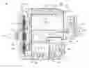
FIG. 1 illustrates a schismatic diagram showing a two-stage oil-injected screw air compressor according to one embodiment of the present invention.
DETAILED DESCRIPTION OF THE PREFERRED EMBODIMENT
The following description is of the best presently contemplated mode of carrying out the present disclosure. This description is not to be taken in a limiting sense but is made merely for the purpose of describing the general principles of the invention. The scope of the invention should be determined by referencing the appended claims.
Referring to FIG. 1, a schismatic diagram showing a two-stage oil-injected screw air compressor according to one embodiment of the present invention is illustrated. The two-stage oil-injected screw air compressor 100 includes an integrated compression casing 200, a front bearing seat 110 fixed at one end of the integrated compression casing 200, a first stage rear bearing seat 130 and a second stage rear bearing seat 140 fixed at another end of the integrated compression casing 200.
The integrated compression casing 200 further includes a first stage compression chamber 220, an intermediate cooling channel 250, and a second stage compression chamber 280, and all of them are formed in the integrated compression casing 200 and stacked in parallel. The arrows 201 denote the air flow direction, and the dashed line arrows denote the injecting oil 302.
The first stage compression chamber 220 further includes first stage screw rotors 230 disposed therein to compress air absorbed from an air inlet 210 into a first stage compressed air, and the first stage compressed air is discharged from a first stage air outlet 240 into the intermediate cooling channel 250. The second stage compression chamber 280 further includes second stage screw rotors 282 disposed therein to further compress the first stage compressed air into a second stage compressed air, having a higher pressure than that of the first stage compressed air. The first stage compressed air is absorbed from the intermediate cooling channel 250 through a second stage air inlet 270 into the second stage compression chamber 280, and further compressed in the second stage compression chamber 280 to form the second stage compressed air and discharge from a second stage air outlet 290.
Furthermore, a gear box 120 is fixed on the front bearing seat 110, and the gear box 120 includes a speed change gear set 122 and a drive shaft 124 coupled to the speed change gear set 122. The drive shaft transmits a power generated by a motor into the speed change gear set 122 to distribute the power into the first stage screw rotors 230 and the second stage screw rotors 282.
A straightforward oil injector 304 aims at the intermediate cooling channel 250 to spray the injecting oil 302, i.e. the lubricating oil, into the intermediate cooling channel 250 and injecting oil 302 is parallel with the intermediate cooling channel 250. Therefore, the cooling efficiency of the two-stage oil-injected screw air compressor 100 is effectively increased.
In addition, the straightforward oil injector 304 can directly mounted on the integrated compression casing 200 to spray the injecting oil 302 into the intermediate cooling channel 250. Alternatively, the two-stage oil-injected screw air compressor 100 can further includes an oil injecting module 300, and the straightforward oil injector 304 is fixed on the oil injecting module 300. The oil injecting module 300 further includes an oil injecting chamber 306 able to guide the first stage compressed air entering into the intermediate cooling channel 250 and the straightforward oil injector 304 sprays the injecting oil 302 parallel with the first stage compressed air while the first stage compressed air entering into the intermediate cooling channel 250.
It is worth noting that the integrated compression casing 200 further includes an intermediate baffle 260 disposed between the first stage compression chamber 220 and the intermediate cooling channel 250, and a rotor end portion 232 of the first stage screw rotors 230 aligns a baffle end portion 262 of the intermediate baffle 260. That is to say, the rotor end portion 232 of the first stage screw rotors 230 is extended to an end edge of the baffle end portion 262 of the intermediate baffle 260.
In one embodiment, the first stage air outlet 240 is a mixed flow air outlet, and the second stage air inlet 270 is a mixed flow air inlet.
In one embodiment, the front bearing seat 110 fixed at one end of the first stage compression chamber 220 and the second stage compression chamber 280, and the first stage rear bearing seat 130 is fixed at another end of the first stage compression chamber 220 and a second stage rear bearing seat 140 is fixed at another end of the second stage compression chamber 280.
The two-stage oil-injected screw air compressor according to one embodiment of the present invention utilizes the straightforward oil injector to directly inject the lubricating oil into the intermediate cooling channel and parallel to the first stage compressed air flowing in the intermediate cooling channel so that the cooling efficiency of the lubricating oil and the two-stage oil-injected screw air compressor is effectively increased.
In addition, the baffle end portion is extended to the end edge of the first stage screw rotors to effectively increase the compression efficiency of the first stage compression chamber to further increased the whole efficiency of the two-stage oil-injected screw air compressor. Therefore, the two-stage oil-injected screw air compressor can be operated more efficient.
As is understood by a person skilled in the art, the foregoing preferred embodiments of the present invention are illustrative of the present invention rather than limiting of the present invention. It is intended that various modifications and similar arrangements be included within the spirit and scope of the appended claims, the scope of which should be accorded the broadest interpretation so as to encompass all such modifications and similar structures.
Claims
What is claimed is:1. A two-stage oil-injected screw air compressor, comprising:
an integrated compression casing, wherein the integrated compression casing further comprises:
a first stage compression chamber;
an intermediate cooling channel; and
a second stage compression chamber, wherein the first stage compression chamber, the intermediate cooling channel and the second stage compression chamber are parallel stacked in the integrated compression casing; and
a straightforward oil injector aiming at the intermediate cooling channel to spray lubricating oil into the intermediate cooling channel and parallel with the intermediate cooling channel.
2. The two-stage oil-injected screw air compressor of claim 1, wherein the first stage compression chamber further comprises first stage screw rotors disposed therein.
3. The two-stage oil-injected screw air compressor of claim 2, wherein the second stage compression chamber further comprises second stage screw rotors disposed therein.
4. The two-stage oil-injected screw air compressor of claim 3, wherein the integrated compression casing further comprises an intermediate baffle disposed between the first stage compression chamber and the intermediate cooling channel, and a rotor end portion of the first stage screw rotors aligns a baffle end portion of the intermediate baffle.
5. The two-stage oil-injected screw air compressor of claim 1, wherein the first stage compression chamber further comprises a mixed flow air outlet.
6. The two-stage oil-injected screw air compressor of claim 5, wherein the second stage compression chamber further comprises a mixed flow air inlet.
7. The two-stage oil-injected screw air compressor of claim 1, further comprising an oil injecting module, wherein the straightforward oil injector is fixed on the oil injecting module and the oil injecting module further comprises an oil injecting chamber to guide air compressed in the first stage compression chamber entering into the intermediate cooling channel.
8. The two-stage oil-injected screw air compressor of claim 1, further comprising a front bearing seat fixed at one end of the first stage compression chamber and the second stage compression chamber, and a first stage rear bearing seat fixed at another end of the first stage compression chamber and a second stage rear bearing seat fixed at another end of the second stage compression chamber.
9. The two-stage oil-injected screw air compressor of claim 8, further comprising a gear box on the front bearing seat.
10. The two-stage oil-injected screw air compressor of claim 8, wherein the gear box comprises a speed change gear set and a drive shaft coupled to the speed change gear set.
Images & Drawings included:
Sources:
- United States Patent and Trademark Office - verify current appl. status at the USPTO↗
Recent applications in this class:
- » 20210207524 2021-07-08
Systems and methods of compression ignition engines - » 20190136745 2019-05-09
Methods and systems for a fuel injector - » 20190078499 2019-03-14
Systems and methods of compression ignition engines - » 20180223723 2018-08-09
Systems and methods of compression ignition engines - » 20180119602 2018-05-03
Oil-injected screw air compressor - » 20180119600 2018-05-03
Oil-injected screw air compressor - » 20170204777 2017-07-20
Systems and methods of compression ignition engines - » 20140234123 2014-08-21
SYSTEMS AND METHODS FOR ENERGY STORAGE AND RECOVERY USING RAPID ISOTHERMAL GAS EXPANSION AND COMPRESSION - » 20120299310 2012-11-29
Systems and methods for energy storage and recovery using rapid isothermal gas expansion and compression - » 20120037118 2012-02-16
Combustion chamber for diesel engines with inclined engine valves
Recent applications for this Assignee:
- » 20240353878 2024-10-24
OIL INJECTED AIR COMPRESSOR AND METHOD FOR CONTROLLING THE SAME, AND STORAGE MEDIUM AND ELECTRONIC DEVICE - » 20200370554 2020-11-26
Rotary screw compressor - » 20180334937 2018-11-22
Built-in oil-gas separating device - » 20180119602 2018-05-03
Oil-injected screw air compressor - » 20180119602 2018-05-03
Oil-injected screw air compressor - » 20180119600 2018-05-03
Oil-injected screw air compressor - » 20180119600 2018-05-03
Oil-injected screw air compressor