Heat exchanger comprising a protective device
US20180120040A1
2018-05-03
15/571,899
2016-05-04
✅ Patent granted
US 10,605,547 B2
2020-03-31
WO; PCT/EP2016/060088; 20160504
WO; WO2016/177831; 20161110
Cassey D Bauer | Jenna M Hopkins
Osha Liang LLP
2036-05-04
Abstract:
The present invention relates to a heat exchanger (20) comprising a protective device (1), mutually parallel tubes (22) through which a first fluid circulates, and perpendicular fins (26) connecting two successive flat tubes (22), a second fluid circulating between said flat tubes (22) by passing through said fins (26), said protective device (1) being apertured so as to allow the circulation of the second fluid through the fins (26), said protective device (1) comprising fixing spikes (7) which are inserted forcibly between the fins (26).
Inventors:
- Fabien Bireaud 8 🇫🇷 Le Mesnil Saint-Denis, France
- Xavier Marchadier 4 🇫🇷 Le Mesnil Saint Denis, France
- José Trindade 5 🇫🇷 Le Mesnil Saint Denis, France
- Dinh-Luyen Nguyen 6 🇫🇷 Le Mesnil Saint Denis, France
Assignee:
- VALEO SYSTEMES THERMIQUES 579 🇫🇷 Le Mesnil-Saint-Denis, France
Applicant:
Interested in similar patents?
Get notified when new applications in this technology area are published.
Classification:
F28F19/002 » CPC main
Preventing the formation of deposits or corrosion, e.g. by using filters or scrapers by using inserts or attachments
F28D1/05366 » CPC further
Heat-exchange apparatus having stationary conduit assemblies for one heat-exchange medium only, the media being in contact with different sides of the conduit wall, in which the other heat-exchange medium is a large body of fluid, e.g. domestic or motor car radiators with heat-exchange conduits immersed in the body of fluid with tubular conduits the conduits being straight the conduits having a non-circular cross-section Assemblies of conduits connected to common headers, e.g. core type radiators
F28F1/126 » CPC further
Tubular elements; Assemblies of tubular elements; Tubular elements and assemblies thereof with means for increasing heat-transfer area, e.g. with fins, with projections, with recesses the means being only outside the tubular element consisting of zig-zag shaped fins
F28D2021/008 » CPC further
Heat-exchange apparatus not covered by any of the groups - ; Other heat exchangers for particular applications; Heat exchange systems not otherwise provided for for vehicles
F28F19/00 IPC
Preventing the formation of deposits or corrosion, e.g. by using filters or scrapers
F28D1/053 IPC
Heat-exchange apparatus having stationary conduit assemblies for one heat-exchange medium only, the media being in contact with different sides of the conduit wall, in which the other heat-exchange medium is a large body of fluid, e.g. domestic or motor car radiators with heat-exchange conduits immersed in the body of fluid with tubular conduits the conduits being straight
F28F1/12 IPC
Tubular elements; Assemblies of tubular elements; Tubular elements and assemblies thereof with means for increasing heat-transfer area, e.g. with fins, with projections, with recesses the means being only outside the tubular element
F28F1/10 IPC
Tubular elements; Assemblies of tubular elements Tubular elements and assemblies thereof with means for increasing heat-transfer area, e.g. with fins, with projections, with recesses
F24D19/065 » CPC further
Details; Casings, cover lids or ornamental panels, for radiators Grids attached to the radiator and covering its top
F24H3/04 IPC
Air heaters with forced circulation the air being in direct contact with the heating medium, e.g. electric heating element
F24D19/067 » CPC further
Details; Casings, cover lids or ornamental panels, for radiators Front coverings attached to the radiator
F24H3/0452 » CPC further
Air heaters with forced circulation the air being in direct contact with the heating medium, e.g. electric heating element using electric energy supply, e.g. the heating medium being a resistive element; Heating by direct contact, i.e. with resistive elements, electrodes and fins being bonded together without additional element in-between; For vehicles Frame constructions
F28F1/105 » CPC further
Tubular elements; Assemblies of tubular elements; Tubular elements and assemblies thereof with means for increasing heat-transfer area, e.g. with fins, with projections, with recesses the means being corrugated elements extending around the tubular elements
F28F9/0135 » CPC further
Casings; Header boxes; Auxiliary supports for elements; Auxiliary members within casings; Auxiliary supports for elements for tubes or tube-assemblies formed by grids having only one tube per closed grid opening
B60R2019/525 » CPC further
Wheel guards; Radiator guards, e.g. grilles ; Obstruction removers; Fittings damping bouncing force in collisions; Radiator or grille guards ; Radiator grilles Radiator grilles
F28F2250/06 » CPC further
Arrangements for modifying the flow of the heat exchange media , e.g. flow guiding means ; Particular flow patterns Derivation channels, e.g. bypass
F28F2265/02 » CPC further
Safety or protection arrangements; Arrangements for preventing malfunction in the form of screens or covers
F28F2275/085 » CPC further
Fastening; Joining by clamping or clipping with snap connection
F28F2275/12 » CPC further
Fastening; Joining by methods involving deformation of the elements
F24D19/06 » CPC further
Details Casings, cover lids or ornamental panels, for radiators
B60R19/52 » CPC further
Wheel guards; Radiator guards, e.g. grilles ; Obstruction removers; Fittings damping bouncing force in collisions Radiator or grille guards ; Radiator grilles
F28F9/013 IPC
Casings; Header boxes; Auxiliary supports for elements; Auxiliary members within casings; Auxiliary supports for elements for tubes or tube-assemblies
F28D21/00 IPC
Heat-exchange apparatus not covered by any of the groups -
F28F9/0131 » CPC further
Casings; Header boxes; Auxiliary supports for elements; Auxiliary members within casings; Auxiliary supports for elements for tubes or tube-assemblies formed by plates
Description
The invention relates to the field of protective devices for a heat exchanger and more particularly for a heat exchanger placed at the front end of a motor vehicle.
In the automotive field, heat exchangers placed at the front end can be a victim of flying debris or stones which can damage or even pierce the flat tubes within which a heat-transfer fluid circulates.
In order to protect these heat exchangers, it is known to place a protective device in front of them which can absorb these impacts. Nevertheless, these protective devices are generally fixed by clips which have to be fitted manually, this being a long and tedious process which is not compatible with rapid mass production. The protective device can also be fixed at the periphery of the heat exchanger but this can cause vibration problems under driving conditions owing to the fact that the protective device is not fixed in its central part.
Thus, one of the aims of the invention is to at least partially overcome the disadvantages of the prior art and to propose a protective device with improved fixing.
The present invention therefore relates to a protective device for a heat exchanger, said heat exchanger comprising mutually parallel tubes in which a first fluid circulates, and perpendicular fins connecting two successive tubes, a second fluid circuiting between said tubes by passing through said fins, said protective device being apertured so as to allow the circulation of the second fluid through the fins, said protective device comprising fixing spikes which are inserted forcibly between the fins.
The presence of these fixing spikes makes it possible to fix the protective device against the heat exchanger by simply pressing it against the heat exchanger. The fixing spikes are thus inserted between the fins, deform them, and hold the protective device in place.
According to one aspect of the invention, said tubes are flat tubes.
According to one aspect of the invention, the fixing spikes have a width which is greater than the spacing between two fins.
According to another aspect of the invention, the fixing spikes are integrally formed with the protective device.
According to another aspect of the invention, the protective device comprises longitudinal bars, which are parallel to one another and cover the sides of the flat tubes, and spacers connecting said longitudinal bars, the fixing spikes being arranged on said spacers.
According to another aspect of the invention, the fixing spikes have a length which is less than the width of the fins.
According to another aspect of the invention, the fixing spikes have a length which is greater than or equal to the width of the fins.
According to another aspect of the invention, the protective device additionally comprises elastic-engagement fixings, said elastic-engagement fixings being positioned between two flat tubes in a peripheral portion of the heat exchanger free of fins.
According to another aspect of the invention, the protective device is made of plastic.
The present invention also relates to a heat exchanger comprising a protective device as described above.
According to one aspect of the heat exchanger according to the invention, at least its lower half comprises the protective device.
Other features and advantages of the invention will become more clearly apparent on reading the following description, given by way of illustrative and nonlimiting example, and from the appended drawings, in which:
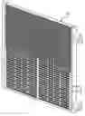
FIG. 1 shows a perspective schematic representation of a protective device,
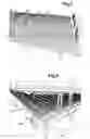
FIG. 2 shows a perspective schematic representation of a protective device during fitting thereof on a heat exchanger,
FIG. 3 shows a schematic representation of a heat exchanger in a rear view at the level of the fixing of the protective device,
FIG. 4 shows a schematic representation of a heat exchanger with a protective device in a front view.
In the various figures, identical elements bear the same reference numbers.
FIGS. 1 and 2 show a protective device 1 for a heat exchanger 20. The heat exchanger 20 comprises tubes 22, which are in this case mutually parallel flat tubes through which a first fluid circulates between manifolds 24. Between these flat tubes 22 there are arranged fins 26 connecting two successive flat tubes 22. A second fluid circulates between said flat tubes 22 by passing through said fins 26.
The protective device 1 is preferably made of plastic and it is apertured so as to allow the circulation of the second fluid through the fins 26. The protective device 1 also comprises fixing spikes 7 which are inserted forcibly between the fins 26 during fitting of said device, as shown in more detail in FIG. 2.
The presence of these fixing spikes 7 makes it possible to fix the protective device 1 against the heat exchanger 20 by simply pressing it against the exchanger 20. The fixing spikes 7 are thus inserted between the fins 2, deform them, and hold said protective device in place.
The number of the fixing spikes 7 and their distribution is adapted for appropriate fixing of the protective device 1 and also for avoiding any vibration thereof under driving conditions.
As shown in FIGS. 1 and 4, the protective device 1 can comprise:
-
- longitudinal bars 3, which are parallel to one another and intended to cover the sides of the flat tubes 22, and
- spacers 5 connecting said longitudinal bars 3.
The fixing spikes 7 are thus arranged on the spacers 5 so as to be positioned opposite the fins 26.
The protective device 1 can for example cover only the lower half of the heat exchanger 20, which is its portion most exposed to impacts since it is closest to the ground.
In order to allow good fixing of the protective device 1, the fixing spikes 7 preferably have a width which is greater than the spacing between two fins 26, as shown in FIG. 3.
The fixing spikes 7 are preferably integrally formed with the fixing device 1 so as to allow straightforward manufacture thereof, for example by molding.
The fixing spikes 7 can have a length which is less than the width of the fins 26 or else a length which is greater than or equal to the width of the fins 26. The determination of the length of the fixing spikes 7 is a function of their number and also of the desired fixing force. The longer the fixing spikes 7, the greater the fixing force.
The protective device 1 can additionally comprise elastic-engagement fixings 9 (clips) which are positioned between two flat tubes 22 in a peripheral portion of the exchanger 20 free of fins 26, as illustrated in FIG. 2. These elastic-engagement fixings 9 reinforce the fixing of the protective device 1 all the more, in particular in the peripheral regions of the heat exchanger 20 where the fins 26 are not present and where vibrations can form.
Thus, it can be clearly seen that the protective device 1, owing to the presence of the multitude of fixing spikes 7, is securely fixed to the heat exchanger 1 and can be installed easily without complex operations.
Claims
1. A heat exchanger, for a motor vehicle, comprising:
a protective device;
mutually parallel tubes through which a first fluid circulate; and
perpendicular fins connecting two successive tubes,
a second fluid circulating between said tubes by passing through said fins,
said protective device being apertured so as to allow the circulation of the second fluid through the fins,
wherein said protective device comprises fixing spikes which are inserted forcibly between the fins.
2. The exchanger according to claim 1, wherein the fixing spikes have a width which is greater than the spacing between two fins.
3. The exchanger as claimed in claim 1, wherein the fixing spikes are integrally formed with the protective device.
4. The exchanger as claimed in claim 1, further comprising longitudinal bars, which are parallel to one another and cover the sides of the tubes, and spacers connecting said longitudinal bars, the fixing spikes being arranged on said spacers.
5. The exchanger as claimed in claim 1, wherein the fixing spikes have a length which is less than the width of the fins.
6. The exchanger as claimed in claim 1, wherein the fixing spikes have a length which is greater than or equal to the width of the fins.
7. The exchanger as claimed in claim 1, further comprising elastic-engagement fixings, said elastic-engagement fixings being positioned between two tubes in a peripheral portion of the heat exchanger free of fins.
8. The exchanger as claimed in claim 1, characterized in that it is made of plastic.
9. The exchanger as claimed in claim 1, wherein at least its lower half comprises the protective device.
Images & Drawings included:

Sources:
- United States Patent and Trademark Office - verify current appl. status at the USPTO↗
Recent applications in this class:
- » 20250146769 2025-05-08
RELATING TO RADIATOR GUARDS - » 20240263894 2024-08-08
RESERVE TANK AND COOLING SYSTEM INCLUDING THE SAME - » 20240255242 2024-08-01
DEVICE AND METHOD FOR REMOVING FOREIGN OBJECT FROM HEAT TRANSFER TUBE - » 20240011725 2024-01-11
PLATE-TYPE HEAT EXCHANGER HAVING BRACKET-REINFORCING STRUCTURE - » 20220397351 2022-12-15
CRACK MITIGATION SYSTEMS AND TECHNIQUES FOR WATER-CONTAINING HOUSINGS SUBJECT TO FREEZING TEMPERATURES - » 20220333880 2022-10-20
Anti-fouling device for heat exchangers and its use - » 20220252362 2022-08-11
A PROTECTION SYSTEM FOR A HEAT EXCHANGER - » 20210364240 2021-11-25
Protection device for a heat exchanger - » 20210302112 2021-09-30
HEAT EXCHANGER WITH SACRIFICIAL TURBULATOR - » 20210071969 2021-03-11
Protection structure for vapor chamber
Recent applications for this Assignee:
- » 20250269700 2025-08-28
MODULE FOR MANAGING FLUIDS FOR A VEHICLE, IN PARTICULAR A MOTOR VEHICLE - » 20250264247 2025-08-21
ELECTRIC HEATING DEVICE FOR A MOTOR VEHICLE - » 20250257893 2025-08-14
METHOD FOR CONTROLLING A THERMAL CONDITIONING SYSTEM - » 20250237282 2025-07-24
ENERGY-ABSORBING DEVICE - » 20250214413 2025-07-03
SHUT-OFF DEVICE ADAPTED TO GENERATE A LIGHTING FUNCTION AND FRONT FACE ASSEMBLY COMPRISING SUCH A DEVICE - » 20250210753 2025-06-26
THERMAL REGULATION DEVICE FOR AN ELECTRICAL ENERGY STORAGE MEMBER - » 20250206104 2025-06-26
THERMAL CONDITIONING SYSTEM - » 20250183754 2025-06-05
SUPPORT FOR A MOTOR AND HEATING, VENTILATION AND/OR AIR-CONDITIONING DEVICE FOR A MOTOR VEHICLE - » 20250172319 2025-05-29
AN ELECTRICAL FLUID HEATER - » 20250170874 2025-05-29
METHOD FOR CONTROLLING A THERMAL CONDITIONING SYSTEM