Camera lens
US20180120540A1
2018-05-03
15/416,114
2017-01-26
✅ Patent granted
US 10,302,910 B2
2019-05-28
-
-
William R Alexander | Jeffrey E Madonna
Na Xu | IPro, PLLC
2037-03-10
Abstract:
A camera lens is disclosed. The camera lens includes a first lens with positive refractive power; a second lens with negative refractive power; a third lens with positive refractive power; a fourth lens with negative refractive power; a fifth lens with positive refractive power; and a sixth lens with negative refractive power. The camera lens further satisfies specific conditions.
Assignee:
- AAC ACOUSTIC TECHNOLOGIES (SHENZHEN) CO., LTD. 368 🇨🇳 Shenzhen, China
Applicant:
Interested in similar patents?
Get notified when new applications in this technology area are published.
Classification:
G02B13/00 IPC
Optical objectives specially designed for the purposes specified below
G02B13/0045 » CPC main
Optical objectives specially designed for the purposes specified below; Miniaturised objectives for electronic devices, e.g. portable telephones, webcams, PDAs, small digital cameras characterised by the lens design having at least one aspherical surface having five or more lenses
G02B9/62 » CPC further
Optical objectives characterised both by the number of the components and their arrangements according to their sign, i.e. + or - having six components only
Description
TECHNICAL FIELD
The present disclosure relates to the technical field of optical elements, and more particularly to a camera lens used in a portable device.
RELATED ART OF THE PRESENT DISCLOSURE
The present invention relates to a camera lens. Particularly it relates to a camera lens very suitable for mobile phone camera module and WEB camera lens etc. equipped with high-pixel camera elements such as CCD, CMOS etc. According to the present invention, the camera lens is composed of six piece lenses with excellent optical properties: TTL (optical length)/IH (image height)≤1.50, ultra-thin, total angle of view (herein after referred to 2ω), above 76° wide angle, F value of high-luminous flux (herein after referred to Fno) Fno is lower than 1.80.
In recent years, various camera devices equipped with camera elements such as CCD, CMOS are extensively popular. Along with development on camera lens toward miniaturization and high performance, ultra-thin and high-luminous flux (Fno) wide angle camera lenses with excellent optical properties are needed in society.
The technology related to the camera lens composed of six piece ultra-thin and high-luminous flux (Fno) wide angle lenses with excellent optical properties is developed gradually. The camera lens mentioned in the proposal is composed of six piece lenses which are arranged sequentially from the object side as follows: a first lens with positive refractive power; a second lens with negative refractive power; a third lens with positive refractive power; a fourth lens with negative refractive power and a fifth lens with positive refractive power; a sixth lens with negative refractive power
The camera lens disclosed in embodiments 1˜6 of the prior Japanese patent publication No. 2016-114633 is composed of above mentioned six piece lenses, but the shape of the first lens is improper; Fno≥2.04 it is not sufficiently bright.
The camera lens disclosed in embodiments 1, 2, 6, 10 of the prior Japanese patent publication No. 2016-136240 is composed of the above mentioned six lenses, but refractive power distribution of the first lens and fourth is insufficient and shape of the first lens is improper; it is not sufficiently ultra-thin.
Therefore, it is necessary to provide an improved camera lens to overcome the disadvantages mentioned above.
BRIEF DESCRIPTION OF THE DRAWINGS
The present invention will hereinafter be described in detail with reference to exemplary embodiments. To make the technical problems to be solved, technical solutions and beneficial effects of present disclosure more apparent, the present disclosure is described in further detail together with the figures and the embodiments. It should be understood the specific embodiments described hereby are only to explain this disclosure, not intended to limit this disclosure.
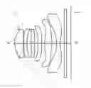
FIG. 1 is a structure diagram of a camera lens LA related to one embodiment of the present disclosure.
FIG. 2 is a structure diagram of the definite Embodiment 1 of the above-mentioned camera lens LA.
FIG. 3 is a spherical aberration diagram of the camera lens LA in Embodiment 1.
FIG. 4 is a magnification chromatic aberration diagram of the camera lens LA in Embodiment 1.
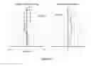
FIG. 5 is an image surface curving diagram and distortion aberration diagram of the camera lens LA in Embodiment 1.
FIG. 6 is a structure diagram of the definite Embodiment 2 of the above-mentioned camera lens LA.
FIG. 7 is spherical aberration diagram of the camera lens LA in Embodiment 2.
FIG. 8 is a magnification chromatic aberration diagram of the camera lens LA in Embodiment 2.
FIG. 9 is an image surface curving diagram and distortion aberration diagram of the camera lens LA in Embodiment 2.
DETAILED DESCRIPTION OF EXEMPLARY EMBODIMENTS
The present invention will hereinafter be described in detail with reference to exemplary embodiments. To make the technical problems to be solved, technical solutions and beneficial effects of present disclosure more apparent, the present disclosure is described in further detail together with the figures and the embodiments. It should be understood the specific embodiments described hereby are only to explain this disclosure, not intended to limit this disclosure.
FIG. 1 is the structure diagram of a camera lens LA related to one embodiment of the invention. The camera lens LA is composed of six piece lenses which are arranged sequentially from the object side to the imaging surface including a first lens L1, a second lens L2, a third lens L3, a fourth lens L4, a fifth lens L5 and a sixth lens L6. A glass plate GF is arranged between the sixth lens L6 and the imaging surface. And a glass cover or an optical filter having the function of filtering IR can be taken as the glass plate GF. Moreover, it shall be fine if no glass plate GF is arranged between the sixth lens L6 and the imaging surface.
The first lens L1 has positive refractive power; the second lens L2 has negative refractive power; the third lens L3 has positive refractive power; the fourth lens L4 has negative refractive power; the fifth lens has positive refractive power, the sixth lens has negative refractive power. Moreover, the surfaces of the six piece lenses should be designed as the aspheric shape preferably in order to correct the aberration well.
The camera lens is characterized in that the camera lens meets following conditions (1)˜(4):
0.85≤f1/f≤1.00 (1)
−5.00≤f2/f≤−2.00 (2)
−20.00≤f4/f≤2.50 (3)
−3.00≤(R1+R2)/(R1−R2)≤−1.80 (4)
where,
f: overall focal distance of the camera lens
f1: focal distance of the first lens
f2: focal distance of the second lens
f4: focal distance of the fourth lens
R1: curvature radius of the first lens' object side surface
R2: curvature radius of the first lens' image side surface
The positive refractive power of the first lens L1 is specified in the condition (1). It is useful for development of ultra-thin trend when the numerical range exceeds the lower limit specified in the condition (1); however, the aberration cannot be corrected easily because the positive refractive power of the first lens L1 becomes too strong; on the contrary, when the numerical range exceeds the upper limit specified, the development of ultra-thin trend cannot be implemented easily because the positive refractive power of the first lens L1 becomes too weak
Therefore, numerical range of condition (1) should be set within the numerical range of the following condition (1-A) preferably,
0.88≤f1/f≤0.98 (1-A)
Negative refractive power of the second lens L2 is specified in the condition (2). Moreover, correction of chromatic aberration on axle and outside axle cannot be implemented easily outside the range of the condition (2).
Therefore, numerical range of condition (2) should be set within the numerical range of the following condition (2-A) preferably,
−3.00≤f2/f≤−2.10 (2-A)
Negative refractive power of the fourth lens L4 is specified in the condition (3). The development of Fno≤1.80 ultra-thin lens with excellent optical properties cannot be easily implemented outside the range of condition (3).
Therefore, numerical range of condition (3) should be set within the numerical range of the following condition (3-A) preferably,
−12.00≤f4/f≤−2.50 (3-A)
The shape of the first lens L1 is specified in the condition (4). The development of Fno≤1.80 ultra-thin lens with excellent optical properties can not be easily implemented outside the range of condition (4).
Therefore, numerical range of condition (4) should be set within the numerical range of the following condition (4-A) preferably,
−2.10≤(R1+R2)/(R1−R2)≤−1.82 (4-A)
The sixth lens L6 has negative refractive power and meets the following condition (5).
−0.70≤f6/f≤s−0.48 (5)
Where,
f: overall focal distance of the camera lens
f6: focal distance of the sixth lens.
Negative refractive power of the sixth lens L6 is specified in the condition (5). The development of Fno≤1.80 ultra-thin lens with excellent optical properties cannot be easily implemented outside the range of condition (5).
Therefore, numerical range of condition (5) should be set within the numerical range of the following condition (5-A) preferably,
−0.65≤f6/f≤−0.50 (5-A)
The second lens L2 has negative refractive power and meets the following condition (6).
2.50≤(R3+R4)/(R3−R4)≤5.00 (6)
where,
R3: curvature radius of the second lens' object side surface
R4: curvature radius of the second lens' image side surface
Shape of the second lens L2 is specified in the condition (6). The development of Fno≤1.80 ultra-thin lens with excellent optical properties cannot be easily implemented outside the range of condition (6).
Therefore, numerical range of condition (6) should be set within the numerical range of the following condition (6-A) preferably,
2.65≤(R3+R4)/(R3−R4)≤4.30 (6-A)
The third lens L3 has positive refractive power and meets the following condition (7).
−3.00≤(R5+R6)/(R5−R6)≤0.70 (7)
Where,
R5: curvature radius of the third lens' object side surface
R6: curvature radius of the third lens' image side surface
The shape of the third lens L3 is specified in the condition (7). The development of Fno≤1.80 ultra-thin lens with excellent optical properties cannot be easily implemented outside the range of condition (7).
Therefore, numerical range of condition (7) should be set within the numerical range of the following condition (7-A) preferably,
−2.60≤(R5+R6)/(R5−R6)≤0.68 (7-A)
Because six piece lenses of the camera Lens LA all have the stated formation and meet all the conditions, so it is possible to produce a camera lens with excellent optical properties, TTL(optical length)/IH(image height)≤1.50,ultra-thin,wide angle 2 ω≥76°,Fno≤1.80.
EMBODIMENTS
The camera lens LA of the invention shall be explained below by using the embodiments. Moreover, the symbols used in all embodiments are shown as follows. And mm shall be taken as the unit of the distance, the radius and the center thickness.
f: overall distance of the camera lens
f1: focal distance of the first lens L1
f2: focal distance of the second lens L2
f3: focal distance of the third lens L3
f4: focal distance of the fourth lens L4
f5: focal distance of the fifth lens L5
f6: focal distance of the sixth lens L6
Fno: F Value
2ω: total angle of view
S1: Open aperture
R: curvature radius of optical surface, if a lens is involved it is central curvature radius
R1: curvature radius of the first lens L1's object side surface
R2: curvature radius of the first lens L1's image side surface
R3: curvature radius of the second lens L2's object side surface
R4: curvature radius of the second lens L2's image side surface
R5: curvature radius of the third lens L3's object side surface
R6: curvature radius of the third lens L3's image side surface
R7: curvature radius of the fourth lens L4's object side surface
R8: curvature radius of the fourth lens L4's image side surface
R9: curvature radius of the fifth lens L5's object side surface
R10: curvature radius of the fifth lens L5's image side surface
R11: curvature radius of the sixth lens L6's object side surface
R12: curvature radius of the sixth lens L6's image side surface
R13: curvature radius of the glass plate GF's object side surface
R14: curvature radius of the glass plate GF's image side surface
d: center thickness of lenses or the distance between lenses
d0: axial distance from open aperture S1 to object side surface of the first lens L1
d1: center thickness of the first lens L1
d2: axial distance from image side surface of the first lens L1 to object side surface of the second lens L2
d3: center thickness of the second lens L2
d4: axial distance from image side surface of the second lens L2 to object side surface of the third lens L3
d5: center thickness of the third lens L3
d6: axial distance from image side surface of the third lens L3 to object side surface of the fourth lens L4
d7: center thickness of the fourth lens L4
d8: axial distance from image side surface of the fourth lens L4 to object side surface of the fifth lens L5
d9: center thickness of the fifth lens L5
d10: axial distance from image side surface of the fifth lens L5 to object side surface of the sixth lens L6
d11: center thickness of the sixth lens L6
d12: axial distance from image side surface of the sixth lens L6 to object side surface of the glass plate GF
d13: center thickness of glass plate GF
d14:axial distance from image side surface to imaging surface of the glass plate GF
nd: refractive power of line d
nd1: refractive power the first lens L1's line d
nd2: refractive power the second lens L2's line d
nd3: refractive power the third lens L3's line d
nd4: refractive power the fourth lens L4's line d
nd5: refractive power the fifth lens L5's line d
nd6: refractive power the sixth lens L6's line d
nd7: refractive power the glass plate GF's line d
νd: abbe number
ν1: abbe number of the first lens L1
ν2: abbe number of the second lens L2
ν3: abbe number of the third lens L3
ν4: abbe number of the fourth lens L4
ν5: abbe number of the fifth lens L5
ν6: abbe number of the sixth lens L6
ν6: abbe number of the glass plate GF
TTL: optical length (axial distance from object side surface to the imaging surface of the first lens L1)
LB: axial distance (including thickness of the glass plate GF) from the image side surface to the imaging surface of the sixth lens L6;
y=(x2/R)/[1+{1−(k+1)(x2/R2)}1/2]+A4x4+A6x6+A8x8+A10x10+A12x12+A14x14+A16x16 (7)
For convenience sake, the aspheric surface shown in the formula (8) shall be taken as the aspheric surfaces of all lens' surfaces. However, the invention shall not be limited to polynomial form of the aspheric surface shown in the formula (8).
Embodiment 1
FIG. 2 is the structure of camera lens LA in Embodiment 1. Data shown in Table 1: curvature radius R of the object side surfaces and the image side surfaces, center thicknesses of the lenses, distances d among the lenses, refractive powers nd and abbe numbers of the lens L1˜L6 in the Embodiment 1, wherein the camera lens LA is formed by the lens L1˜L6; Data shown in Table 2: conical coefficients k and aspheric coefficients
| TABLE 1 | ||||
| R | d | nd | vd | |
| S1 | ∞ | d0 = | −0.380 | ||||
| R1 | 1.55471 | d1 = | 0.701 | nd1 | 1.5439 | v1 | 55.95 |
| R2 | 5.26613 | d2 = | 0.057 | ||||
| R3 | 5.53896 | d3 = | 0.244 | nd2 | 1.6614 | v2 | 20.41 |
| R4 | 2.97081 | d4 = | 0.359 | ||||
| R5 | 5.79828 | d5 = | 0.279 | nd3 | 1.5439 | v3 | 55.95 |
| R6 | 16.69374 | d6 = | 0.275 | ||||
| R7 | 15.27303 | d7 = | 0.298 | nd4 | 1.6355 | v4 | 23.97 |
| R8 | 5.14561 | d8 = | 0.258 | ||||
| R9 | 3.53499 | d9 = | 0.591 | nd5 | 1.5439 | v5 | 55.95 |
| R10 | −2.87935 | d10 = | 0.380 | ||||
| R11 | −4.78983 | d11 = | 0.295 | nd6 | 1.5352 | v6 | 56.12 |
| R12 | 1.87708 | d12 = | 0.325 | ||||
| R13 | ∞ | d13 = | 0.210 | nd7 | 1.5168 | v7 | 64.17 |
| R14 | ∞ | d14 = | 0.344 | ||||
| TABLE 2 | ||
| conical coefficient | aspheric coefficient |
| k | A4 | A6 | A8 | A10 | A12 | A14 | A16 | |
| R1 | −4.1537E−01 | −2.7648E−03 | 1.9120E−02 | −4.5661E−02 | 6.3496E−02 | −5.3229E−02 | 2.2320E−02 | −5.1430E−03 |
| R2 | 1.3136E+01 | −1.7646E−01 | 1.6752E−01 | −6.5697E−02 | −7.8037E−02 | 1.0911E−01 | −5.2583E−02 | 8.2174E−03 |
| R3 | 1.7944E+01 | −1.9200E−01 | 2.2247E−01 | −4.0851E−02 | −1.7639E−01 | 2.0683E−01 | −8.9084E−02 | 1.3808E−02 |
| R4 | 6.3203E+00 | −9.4604E−02 | 9.9614E−02 | 3.9979E−02 | −2.1010E−01 | 1.7154E−01 | −9.7355E−03 | −3.1648E−02 |
| R5 | −1.2877E+01 | −5.8142E−02 | −2.0807E−02 | 1.9515E−01 | −6.5706E−01 | 9.9293E−01 | −7.4955E−01 | 2.2641E−01 |
| R6 | 6.6959E+01 | −9.9802E−02 | 9.7225E−02 | −1.3934E−01 | 6.7759E−02 | 4.9722E−03 | −1.9512E−02 | 1.3637E−02 |
| R7 | 1.5299E+01 | −2.4024E−01 | 2.1729E−01 | −2.1596E−01 | 1.7944E−01 | −1.1876E−01 | 5.4647E−02 | −1.1998E−02 |
| R8 | −5.2891E+01 | −1.9735E−01 | 6.7224E−02 | 3.5617E−02 | −8.7818E−02 | 7.3475E−02 | −2.7345E−02 | 3.6137E−03 |
| R9 | 1.5936E+00 | −8.6218E−03 | −7.3209E−02 | 6.6155E−02 | −5.2093E−02 | 2.3922E−02 | −5.6532E−03 | 5.3405E−04 |
| R10 | −2.7125E+01 | 5.2315E−02 | 7.6396E−03 | −3.5550E−02 | 1.7698E−02 | −4.1715E−03 | 4.8599E−04 | −2.2844E−05 |
| R11 | 2.2479E−01 | −1.6943E−01 | 1.1673E−01 | −4.3850E−02 | 1.0455E−02 | −1.5036E−03 | 1.1848E−04 | −3.9781E−06 |
| R12 | −1.2119E+01 | −1.0748E−01 | 5.7381E−02 | −2.1975E−02 | 5.0393E−03 | −6.5946E−04 | 4.5411E−05 | −1.2561E−06 |
The values in embodiments 1 and 2 and the values corresponding to the parameters specified in the conditions (1)-6 are shown in subsequent Table 5.
As shown on Table 5, the Embodiment 1 meets the conditions (1)˜(7).
Spherical aberration of camera lens LA in embodiment 1 is shown in FIG. 3, magnification chromatic aberration of the same is shown in FIG. 4, image surface curving and distortion aberration of the same is shown in FIG. 5. Furthermore, image surface curving S in FIG. 5 is the one opposite to the sagittal image surface, T is the one opposite to the tangent image surface. Same applies for the Embodiment 2. As shown in FIG. 3˜5, the camera lens in embodiment 1 has the properties as follows: 2ω=76.6° TTL/IH=1.467 Fno=1.78, so camera lens ultra-thin, high-luminous flux wide angle camera lens, it is not difficult to understand why it has excellent optical properties.
Embodiment 2
FIG. 6 is the structure of camera lens LA in Embodiment 2. Data shown in Table 3: curvature radius R of the object side surfaces and the image side surfaces, center thicknesses of the lenses, distances d among the lenses, refractive powers nd and abbe numbers of the lens L1˜L6 in the Embodiment 2, wherein the camera lens LA is formed by the lens L1˜L6; Data shown in Table 4: conical coefficients k and aspheric coefficients
| TABLE 3 | ||||
| R | d | nd | vd | |
| S1 | ∞ | d0 = | −0.380 | ||||
| R1 | 1.55270 | d1 = | 0.698 | nd1 | 1.5439 | v1 | 55.95 |
| R2 | 5.25350 | d2 = | 0.058 | ||||
| R3 | 5.56744 | d3 = | 0.244 | nd2 | 1.6614 | v2 | 20.41 |
| R4 | 2.97320 | d4 = | 0.358 | ||||
| R5 | 5.82780 | d5 = | 0.280 | nd3 | 1.5439 | v3 | 55.95 |
| R6 | 17.13227 | d6 = | 0.275 | ||||
| R7 | 15.99220 | d7 = | 0.300 | nd4 | 1.6355 | v4 | 23.97 |
| R8 | 5.14349 | d8 = | 0.265 | ||||
| R9 | 3.53681 | d9 = | 0.591 | nd5 | 1.5439 | v5 | 55.95 |
| R10 | −2.86450 | d10 = | 0.380 | ||||
| R11 | −4.78646 | d11 = | 0.295 | nd6 | 1.5352 | v6 | 56.12 |
| R12 | 1.87902 | d12 = | 0.325 | ||||
| R13 | ∞ | d13 = | 0.210 | nd7 | 1.5168 | v7 | 64.17 |
| R14 | ∞ | d14 = | 0.345 | ||||
| TABLE 4 | ||
| conical coefficient | aspheric coefficient |
| k | A4 | A6 | A8 | A10 | A12 | A14 | A16 | |
| R1 | −4.1266E−01 | −3.3391E−03 | 1.9071E−02 | −4.5753E−02 | 6.3439E−02 | −5.3255E−02 | 2.2308E−02 | −5.1500E−03 |
| R2 | 1.3086E+01 | −1.7716E−01 | 1.6742E−01 | −6.5764E−02 | −7.8094E−02 | 1.0908E−01 | −5.2591E−02 | 8.2180E−03 |
| R3 | 1.8041E+01 | −1.9146E−01 | 2.2247E−01 | −4.1031E−02 | −1.7646E−01 | 2.0677E−01 | −8.9126E−02 | 1.3775E−02 |
| R4 | 6.3050E+00 | −9.3923E−02 | 1.0018E−01 | 4.0544E−02 | −2.1129E−01 | 1.7017E−01 | −1.0093E−02 | −3.0911E−02 |
| R5 | −1.1754E+01 | −5.7974E−02 | −2.1121E−02 | 1.9509E−01 | −6.5700E−01 | 9.9299E−01 | −7.4949E−01 | 2.2645E−01 |
| R6 | 7.3584E+01 | −9.9884E−02 | 9.8199E−02 | −1.3896E−01 | 6.7752E−02 | 5.0259E−03 | −1.9434E−02 | 1.3727E−02 |
| R7 | 1.8424E+01 | −2.3998E−01 | 2.1720E−01 | −2.1585E−01 | 1.7964E−01 | −1.1861E−01 | 5.4706E−02 | −1.2006E−02 |
| R8 | −5.5690E+01 | −1.9717E−01 | 6.7359E−02 | 3.5636E−02 | −8.7823E−02 | 7.3469E−02 | −2.7348E−02 | 3.6123E−03 |
| R9 | 1.5754E+00 | −8.8915E−03 | −7.3234E−02 | 6.6162E−02 | −5.2093E−02 | 2.3920E−02 | −5.6542E−03 | 5.3361E−04 |
| R10 | −2.5964E+01 | 5.2362E−02 | 7.6121E−03 | −3.5555E−02 | 1.7697E−02 | −4.1717E−03 | 4.8599E−04 | −2.2850E−05 |
| R11 | 2.1959E−01 | −1.6943E−01 | 1.1674E−01 | −4.3848E−02 | 1.0455E−02 | −1.5036E−03 | 1.1846E−04 | −3.9872E−06 |
| R12 | −1.1616E+01 | −1.0746E−01 | 5.7376E−02 | −2.1976E−02 | 5.0392E−03 | −6.5946E−04 | 4.5411E−05 | −1.2558E−06 |
As shown on Table 5, the Embodiment 2 meets the conditions (1)˜(7).
Spherical aberration of camera lens LA in embodiment 2 is shown in FIG. 7, magnification chromatic aberration of the same is shown in FIG. 8, image surface curving and distortion aberration of the same is shown in FIG. 9. As show in FIG. 7˜9, the camera lens in embodiment 2 has the properties as follows: 2ω=76. 5° TTL/IH=1.469 Fno=1.79, so camera lens ultra-thin, high-luminous flux wide angle camera lens, it is not difficult to understand why it has excellent optical properties.
The values in all embodiments and the values corresponding to the parameters specified in the conditions (1)˜(5) are shown in the Table 7. Furthermore, units of various values in Table 5 are respectively 2ω(°) f (mm) f1 (mm) f2 (mm) f3 (mm) f4 (mm) f5 (mm) f6 (mm) TTL (mm) LB (mm) IH (mm).
| TABLE 5 | |||
| Embodiment 1 | Embodiment 2 | Condition | |
| f1/f | 0.969 | 0.964 | 1 |
| f2/f | −2.568 | −2.546 | 2 |
| f4/f | −3.150 | −3.064 | 3 |
| (R1 + R2)/(R1 − R2) | −1.838 | −1.839 | 4 |
| f6/f | −0.633 | −0.631 | 5 |
| (R3 + R4)/(R3 − R4) | 3.314 | 3.292 | 6 |
| (R5 + R6)/(R5 − R6) | −2.064 | −2.031 | 7 |
| Fno | 1.78 | 1.79 | |
| 2ω | 76.6 | 76.5 | |
| TTL/IH | 1.467 | 1.469 | |
| f | 3.925 | 3.940 | |
| f1 | 3.803 | 3.800 | |
| f2 | −10.078 | −10.032 | |
| f3 | 16.188 | 16.098 | |
| f4 | −12.364 | −12.072 | |
| f5 | 3.015 | 3.008 | |
| f6 | −2.484 | −2.485 | |
| TTL | 4.616 | 4.624 | |
| LB | 0.879 | 0.880 | |
| IH | 3.147 | 3.147 | |
It is to be understood, however, that even though numerous characteristics and advantages of the present exemplary embodiments have been set forth in the foregoing description, together with details of the structures and functions of the embodiments, the disclosure is illustrative only, and changes may be made in detail, especially in matters of shape, size, and arrangement of parts within the principles of the invention to the full extent indicated by the broad general meaning of the terms where the appended claims are expressed.
Claims
What is claimed is:1. A camera lens comprising, arranged sequentially from an object side to an image side:
a first lens with positive refractive power;
a second lens with negative refractive power;
a third lens with positive refractive power;
a fourth lens with negative refractive power;
a fifth lens with positive refractive power; and
a sixth lens with negative refractive power, wherein the camera lens satisfies following conditions (1)˜(4):
0.85≤f1/f≤1.00 (1)
−5.00≤f2/f≤−2.00 (2)
−20.00≤f4/f≤2.50 (3)
−3.00≤(R1+R2)/(R1−R2)<−1.80 (4)
where,
f: overall distance of the camera lens;
f1: focal distance of the first lens;
f2: focal distance of the second lens;
f4: focal distance of the fourth lens;
R1: curvature radius of the first lens' object side surface;
R2: curvature radius of the first lens' image side surface.
2. The camera lens as described in claim 1 further satisfying following condition (5):
−0.70≤f6/f≤s−0.48 (5)
where,
f: overall distance of the camera lens;
f6: focal distance of the sixth lens.
3. The camera lens as described in claim 1 further satisfying following condition (6):
2.50≤(R3+R4)/(R3−R4)<5.00 (6)
where,
R3: curvature radius of the second lens' object side surface;
R4: curvature radius of the second lens' image side surface.
4. The camera lens as described in claim 1 further satisfying following condition (7):
−3.00≤(R5+R6)/(R5−R6)≤0.70 (7)
where,
R5: curvature radius of the third lens' object side surface;
R6: curvature radius of the third lens' image side surface.
Images & Drawings included:


Sources:
- United States Patent and Trademark Office - verify current appl. status at the USPTO↗
Similar patent applications:
- » 20200150388
Camera lens processing method, camera lens, camera assembly and electronic device - » 20130250109
Multi-lens camera system, vehicle mounting the multi-lens camera system, and range-finding method executed by the multi-lens camera system - » 20210088757
Multi-lens camera lens, camera module, and terminal including a lens providing a diffractive surface concave to the image side plane - » 20240118459
MOTOR FOR DRIVING LIQUID STATE CAMERA LENS, CAMERA LENS ASSEMBLY, AND TERMINAL DEVICE - » 20180231737
Camera lens, camera and method of locking a focus ring in a camera lens - » 20240244309
CAMERA LENS MODULE, CAMERA LENS OPTICAL AXIS ADJUSTING DEVICE, AND BINOCULAR CAMERA - » 20190129073
CAMERA LENS AND CAMERA LENS ASSEMBLY HAVING SAME - » 20210352196
INTEGRATED LENS BARREL, OPTICAL CAMERA LENS, CAMERA MODULE AND ASSEMBLY METHOD THEREOF - » 20190243093
Camera lens assembly and camera device equipped with camera lens assembly - » 20180292628
Camera lens assembly and camera device equipped with camera lens assembly
Recent applications in this class:
- » 20250291158 2025-09-18
IMAGING OPTICAL LENS ASSEMBLY, IMAGING APPARATUS AND ELECTRONIC DEVICE - » 20250291157 2025-09-18
OPTICAL IMAGING LENS ASSEMBLY - » 20250284101 2025-09-11
OPTICAL SYSTEM AND IMAGE PICKUP APPARATUS - » 20250284100 2025-09-11
OPTICAL SYSTEM, IMAGING DEVICE, IN-VEHICLE SYSTEM, AND MOVABLE APPARATUS - » 20250284099 2025-09-11
OPTICAL IMAGING SYSTEM - » 20250284098 2025-09-11
LENS MODULE - » 20250284097 2025-09-11
OPTICAL SYSTEM, CAMERA MODULE, AND ELECTRONIC DEVICE - » 20250284096 2025-09-11
CAMERA OPTICAL LENS - » 20250284095 2025-09-11
CAMERA OPTICAL LENS - » 20250277961 2025-09-04
IMAGING LENS SYSTEM AND CAMERA MODULE
Recent applications for this Assignee:
- » 20250126386 2025-04-17
MEMS microphone - » 20250080917 2025-03-06
Speaker module and assembling method thereof - » 20250056163 2025-02-13
Sounding Device - » 20250042722 2025-02-06
MEMS microphone - » 20250039600 2025-01-30
SINGLE-END-TO-DIFFERENTIAL MICROPHONE CIRCUIT AND ELECTRONIC EQUIPMENT - » 20250038713 2025-01-30
Single-end-to-differential microphone circuit - » 20250024199 2025-01-16
Microphone amplifying circuit design method and microphone amplifying circuit - » 20240393821 2024-11-28
TRIGGER MODULE WITH FORCE FEEDBACK - » 20240284093 2024-08-22
Microphone module - » 20240219293 2024-07-04
Gas Sensor