Random Walk Polishing Machine
US20180161955A1
2018-06-14
15/471,962
2017-03-28
Abstract:
A polishing machine for fine polishing and abrading work configured to employ a random walk theory algorithm to generate the movement pattern of the polishing or abrading element.
Interested in similar patents?
Get notified when new applications in this technology area are published.
Classification:
B24B51/00 » CPC main
Arrangements for automatic control of a series of individual steps in grinding a workpiece
B24B1/00 » CPC further
Processes of grinding or polishing; Use of auxiliary equipment in connection with such processes
Description
RELATED APPLICATIONS
This application claims the benefit of priority under 35 U.S.C. 119(e) of the Provisional Application No. 62/432,886 filed Dec. 12, 2016. This provisional application is incorporated by reference herein in its entirety.
BACKGROUND OF THE INVENTION
The present invention relates to apparatuses and methods for abrading or polishing a surface of a workpiece. The abrading or polishing of the surface of a workpiece is a technique that has many different applications in a variety of technical fields, including the production of semi-conductor devices, optical fiber connectors, mirrors, prisms, lenses and other optical components. It is desirable in these fields, and others, to employ a fine polishing or abrading process that results in a particular and specific surface profile and a particular and specific surface finish, i.e., smoothness. This is typically accomplished by means of a tool that is moved across the workpiece while the workpiece is held stationary. Several apparatuses and processes have been developed to accomplish the fine movement of a polishing tool in this manner. For example, U.S. Pat. No. 4,128,968, discloses a polishing apparatus and system whereby two polishing pads are maintained in contact with the surface of the workpiece and are relatively rotated and moved in a spiraling path around the surface of the workpiece. Another technique is disclosed in PCT No. W097/00155, which uses a tool that has a flexible working surface so that the effective area of contact with the workpiece can be controlled. In these and other prior art techniques, the tool is usually spun around an axis normal to the workpiece or parallel to the surface of the workpiece. Since regular tool paths across the same portion of the workpiece invariably create grooves and ridges in the surface of the workpiece, prior art designs have included apparatuses and methods whereby the abrading tool employs a non-closed orbits movement or a figure-eight movement. This is designed to avoid repeated polishing paths over the same area. This is obtained in the case of FIG. 8 movement imposing a lateral displacement of the of the abrasive platform after cycles of number 8 figure.
However, polishing and abrading machines that employ these movement techniques are expensive to manufacture as the tools, the tool mounting, and the associated machinery all require a high level of mechanical precision.
What is needed therefore are abrading and polishing machines and methods suitable for use over a wide variety of materials, that is relatively easy to operate, that utilizes tool movements designed to ensure that the polished surface is free of grooves or ridges, and that is easy and inexpensive to manufacture.
General Description:
According to the present invention there is provided a novel automated polishing apparatus and method configured to move the polishing/abrading tool over the workpiece surface in a pattern that replicates on a macroscopic scale the random motion seen in the Brownian motion of microscopic particles. The apparatus employing such movements can be manufactured in a variety of ways, but always based on the same principle of random walk. Such a method of employing a random walk movement of an abrasive platform under or over the pieces to be lapped, abrading or polished being suitable for curved surfaces, plane surfaces, for optical connections, and other precise optical parts including mirrors, prisms, and lenses. Brownian motion is the random motion of particles suspended in a fluid (liquid or gas) resulting from their collision with the fast moving atoms or molecule in the gas or liquid. This phenomenon has been shown to result in a movement that over time reproduces statistically a normal distribution with a perfectly symmetrical around the center polishing or abrading configuration. Further, for polishing convex surfaces, as, for example, those found in optical fiber connectors, the result is that the apex eccentricity equals to zero, which is a desired characteristic in polishing and abrading such objects.
An apparatus and method is provided whereby a machine employs a processing unit to execute a previously embedded sequence of steps corresponding to a positive and negative sequence of numbers whose algebraic sum is zero, chosen among many sequences of randomly generated numbers. This sequence can be imagined broken in minor chains of random sequences in order that the sum of all distributions trends to be a Gaussian distribution, according the “Central Limit Theorem”, well known theorem of statistics textbooks. The numbers are then normalized and transformed by the polishing apparatus into displacement of a polishing tool or polishing platform. This is accomplished by means of motors connected to a drive system which move the polishing platform based on commands provided to it by the processing unit. A workpiece to be polished and/or abraded is secured to the apparatus and brought into contact to the polishing platform. The polishing platform is then displaced pursuant to the random number set generated by the processing unit. The displacement, be it horizontal, vertical, right, left, up, down or any other direction is, averaged over time, is zero. In addition, the path is not repetitive due the intrinsic nature of the movement. Any groove or ridge in the surface of the workpiece created by the movement of the polishing tool over a particular path is removed or smoothed by the movement of the polishing tool in another direction. Further, this random movement consisting of a zero-sum displacement in any particular direction will result in no apex eccentricity of a parabolic surface being polished. As a result, for convex surfaces, a smooth surface with no apex eccentricity can be achieved.
BRIEF DESCRIPTION OF THE DRAWINGS
The invention will be more readily understood with reference to the accompanying drawings, wherein like reference numerals refer to like components throughout the several views.
FIG. 1 is a perspective view of an embodiment of the invention.
FIG. 2 is a perspective view of another embodiment of the invention.
DETAILED DESCRIPTION OF THE INVENTION
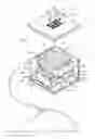
The present invention relates in general to a random movement abrading system for lapping surfaces of a workpiece. As shown in FIG. 1, a polishing machine (100) of a particular embodiment of the invention comprises a processing unit (1) in electronic communication with a polisher housing (22). As shown in FIG. 1, the polisher housing (22) comprises an x-axis frame (10) disposed inside the polisher housing (22) and preferably is defined by a bottom surface (101) of a generally rectangular shape secured to the inner bottom surface of the polisher housing (22) and a first side wall (102) secured to one end of the bottom surface (101) and extending upward from the bottom surface (101) and a second side wall (103) secured to the opposite end of the bottom surface (101) and extending upward from the bottom surface (101). So configured, the bottom surface (101) and the first and second side walls (102), (103) of the x-axis frame (10) define an x-axis space (104). Secured within the x-axis space (104) is an x-axis table (4) configured to allow for its movement within the x-axis space (104) along the x-axis, or in the horizontal direction, relative to the polisher housing (22). In a preferred embodiment, movement of the x-axis table is accomplished by means of an x-axis motor (2) in communication with rack (7) and pinion (6) gears secured to the underside of the x-axis table.
The polisher housing (22) further comprises a y-axis frame (11) disposed inside the polisher housing (22) and further disposed above the x-axis table (4). Like the x-axis frame (4), the y-axis frame (11) is preferably defined by a bottom surface (105) of a generally rectangular shape and a first side wall (106) secured to one end of the bottom surface (105) and extending upward from the bottom surface (105) and a second side wall (107) secured to the opposite end of the bottom surface (105) and extending upward from the bottom surface (101). Each side wall (106) and (107) comprises at least one attachment means to secure the y-axis frame (11) to the polisher housing (22). So configured, the bottom surface (105) and the first and second side walls (106) and (107) of the y-axis frame (11) define a y-axis space (108). Secured within the y-axis space (108) is an y-axis table (5) configured to allow for its movement within the y-axis space (108) along the y-axis, or in the vertical direction, relative to the polisher housing (22). Movement of the y-axis table (5) is accomplished by means of a y-axis motor (3) in communication with rack (109) and pinion (110) gears secured to the underside of the y-axis table (5). Disposed upon the top of the y-axis table (5) is an abrading material (24). As shown in the embodiment in FIG. 1, the preferred abrading material (24) chosen will typically be sandpaper.
The x-axis frame (10) further comprises two horizontal sensors (14) and (15) which in a preferred embodiment will be of a magnetic type and configured to control and limit movement of the x-axis table (4). Similarly, the y-axis frame (11) further comprises two vertical sensors (12) and (13) which in a preferred embodiment will be of a magnetic type and configured to control and limit movement of the y-axis table (5). The horizontal and vertical sensors control and limit movement of the respective x-axis and y-axis tables by sensing proximity of the tables within either the x-axis space (104) or y-axis space (108) and preventing movement of the tables in a manner which would cause the tables to contact each other and/or to prevent each table from contacting either the x-axis frame (10) or y-axis frame (11).
An abrading template (20) is provided of a generally rectangular shape with dimensions sufficient to provide for the abrading template (20) to be removably secured to the top of the polisher housing (22). Disposed along the abrading template (20) are embedded supports (21) configured to accept a workpiece (25) and further configured to secure the workpiece (25) in a manner that ensures the surface of the workpiece (25) remains in contact with the abrading material (24). In the embodiment shown in FIGS. 1, the workpiece consists of optical fiber connectors, and the embedded supports (21) are configured to hold the tips of the connectors with sufficient pressure on the abrading material (24).
Operation of the polishing machine (100) begins with the processing unit (1) generating and storing a set of random numbers and assigning each number generated a specific directional displacement. The processing unit (1) selects from these stored numbers a series of numbers whose sum for each directional displacement is zero. The processing unit (1) transforms these displacements into movement commands to either the x-axis motor (2) or y-axis motor (3) whereupon the motors cause movement of the rack and pinions (6) and (7) thereby imparting horizontal movement to the x-axis table (4) and vertical movement to the y-axis table (5). The resulting random movement of the abrading material provides abrading and/or polishing of the workpiece over a series of random paths with no risk of grooves in the surface and, for convex material, no apex eccentricities.
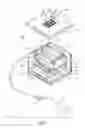
FIG. 2 shows another embodiment of the invention wherein the polishing unit comprises a polisher housing (220) that is generally cylindrical in shape and which comprises a base (130) and case (120), and an upper plate (90). A cushion (140) is provided upon which the base (130) rests. The cushion (140), preferably is formed of rubber. A plane platform (60) is disposed along the top of the upper plate (90) and a pad (70), preferably formed of a hard rubber, is disposed along the top of the plane platform (60). Disposed within the housing (220), is a motor assembly (130), comprising a lower motor (210) secured to the Base (130) and coupled to an upper motor (205) by means of a flange (50). An upper eccentric ball bearing (30) is disposed on top of the upper motor (20) and a lower eccentric ball bearing (40) is disposed on top of the lower motor (210). The motor assembly (100) is further secured within the housing by means of a blocking ring (10) which is threadably secured to the housing (130) by means of a retention screw (110). The motor assembly is positioned within the housing so that the upper eccentric ball bearing is in secured contact with the underside of the plane platform (60)
A sanding disc (80) is secured to the top surface of a rubber pad (70) that stays over a platform, which in this embodiment is plane and circular, but, it is understood that other embodiments of the platform within the scope of the invention may not necessarily be plane and circular. A circular abrading template (150) is provided that is removably secured to the upper plate (90) and comprises embedded supports (170) disposed along the surface of the template (150). The embedded supports are configured to allow insertion and retention of a workpiece and further configured to allow the surface of the workpiece to be in contact with the sanding disc (80) when the abrading template (B150) is secured to the upper plate (90). The random motion of the sanding disc (80) is accomplished by the combination of the oscillatory motions created by the two motors when operated simultaneously. The blocking ring (211) secured to the housing (130) As shown in FIG. 2, the lower motor (210) is powered by a lower power unit (300) and the upper motor is powered by a separate upper power unit (400). In a preferred method, each power unit will apply power to its respective motor at a different frequency and phase, both of which would be uncorrelated among and between themselves. The resulting oscillatory motions of the motors are transmitted through the motor assembly (130) to create a random movement of the abrading disc (80).
In the embodiment shown in FIG. 2, the abrading template (150) is configured to accept and retain optical connectors. In this configuration, a preferred method may include fastening weights (180) to the connectors to aid in securing the workpiece (160) to the abrading template (170) as well as aiding in maintain proper contact pressure of the workpiece (160) against the abrading disc (80). It is also contemplated and understood that in this embodiment, the abrading template (170) can be configured to accept a variety of workpieces, including, for example, jewelry, optical devices, lenses and various metallurgical samples.
The above-described embodiments relate also to methods for performing a surface treatment on a workpiece. The method for performing such a surface treatment would comprise, in a preferred method, generating a series of random paths which visit all points of a surface area and moving the surface treatment device along the series of random paths such that the surface treatment device passes over all points of the workpiece. This and other similar methods are thus described.
Although the present invention has been described herein above with reference to specific embodiments, it will be apparent to a skilled person in the art that the present invention is not limited to the specific embodiments and modifications can be made within the spirit and scope of the invention.
Claims
1. A machine for polishing a workpiece, the machine comprising:
a supporting surface for securing and supporting the workpiece;
a polishing surface for polishing the workpiece;
a mounting arrangement for supporting said supporting surface and said polishing surface;
a movement arrangement for moving said polishing surface with respect to said supporting surface and across said workpiece;
a control system in electronic communication with said movement arrangement for directing the movement of said polishing surface with said control system configured to generate a sequence of displacement commands by means of generating a series of random numbers, assigning movement directions to each random number in said series such that the sum of the random numbers corresponding to each of the assigned movement directions equals zero;
whereby said polishing surface, in response to said sequence of displacement commands, moves across said workpiece in a number of non-repeating polishing paths.
2. The machine for polishing a workpiece of claim 1 wherein said movement arrangement comprises a horizontal platform configured to move said polishing surface in its horizontal plane and a vertical platform configured to move said polishing surface in its vertical plane in response to said sequence of displacement commands, wherein said horizontal platform further comprises an x-axis motor and at least one horizontal sensor configured to control and limit movement of said horizontal platform and wherein said vertical platform comprises a y-axis motor and at least one vertical sensor configured to control and limit movement of said vertical platform.
3. The machine for polishing a workpiece of claim 1 wherein said polishing surface has either a plane or curved shape and said polishing surface executes random-walk movements across said workpiece wherein said random-walk movements do not replicate a planetary movement or figure-eight pattern movement.
4. The machine for polishing a workpiece of claim 1 wherein the polishing surface comprises a removable sanding pad.
5. The machine for polishing a workpiece of claim 1 wherein the supporting surface comprises embedded supports to support the workpiece.
6. A machine for polishing a workpiece comprising:
a supporting surface for securing and supporting the workpiece;
a polishing surface for polishing the workpiece;
a mounting arrangement for supporting said supporting surface and said polishing surface with said mounting arrangement configured in a generally cylindrical shape and comprising a base, a casing and an upper plate;
a movement arrangement for moving said polishing surface with respect to said supporting surface and across said workpiece with said movement arrangement housed within the said casing of said mounting arrangement and comprising a first oscillatory motor situated below a second oscillatory motor and with a first eccentric ball bearing disposed on the top of the first oscillatory motor and a second eccentric ball bearing disposed on top of the second oscillatory motor and with the movement arrangement further configured such that the second eccentric ball bearing is in contact with the polishing surface;
a first power source to operate the first oscillatory motor and a second power source to operated the second oscillatory motor,
whereby said polishing surface moves across said workpiece in a number of random polishing paths generated by the combined operation of the first oscillatory motor operating at a first frequency and the second oscillatory motor operating at a second frequency.
7. The machine for polishing a workpiece of claim 6 wherein the first oscillatory motor is coupled to the second oscillatory motor by means of a flange.
8. The machine for polishing a workpiece of claim 6 wherein the movement arrangement is secured within the case of the mounting arrangement by means of a blocking ring.
9. The machine for polishing a workpiece of claim 6 wherein the upper plate of said mounting arrangement further comprises a rubber sanding pad.
10. The machine for polishing a workpiece of claim 6 wherein the polishing surface comprises removable sanding pads.
11. The machine for polishing a workpiece of claim 6 wherein the supporting surface comprises embedded supports for supporting the workpiece.
12. The machine for polishing a workpiece of claim 6 wherein said polishing surface has either a plane or curved shape and said polishing surface executes random-walk movements across said workpiece wherein said random-walk movements do not replicate a planetary movement or figure-eight pattern.
13. A method for polishing a workpiece comprising the steps of:
Generating and storing a random set of numbers;
Assigning a directional displacement value to each number;
Selecting from the stored set of numbers a subset of the numbers whose sum equals zero;
Translate the displacement value of each number in the subset into a movement command;
Communicate that movement command to a polishing surface for movement of said polishing surface over a workpiece.
14. The method for polishing a workpiece of claim 13 further comprising the steps of:
Securing a workpiece to a support apparatus;
Disposing the workpiece on a polishing surface;
transmitting an oscillatory movement generated by the operation of coupled oscillatory motors disposed within a support housing secured to said polishing surface;
operating the coupled oscillatory motors at different frequencies;
and transmitting the oscillatory motion of the coupled oscillatory motors to the polishing surface.
Images & Drawings included:

Sources:
- United States Patent and Trademark Office - verify current appl. status at the USPTO↗
Similar patent applications:
- » 20220250202
Random Walk Polishing Machine
Recent applications in this class:
- » 20250083281 2025-03-13
LAWN MOWER BLADE GRINDING MACHINE WITH CONNECTED CONTROLS - » 20250025986 2025-01-23
GRINDING METHOD OF WAFER - » 20250010430 2025-01-09
WORKPIECE GRINDING METHOD - » 20250010429 2025-01-09
LOAD ADJUSTING SYSTEM AND LOAD ADJUSTING METHOD - » 20240424638 2024-12-26
SYSTEM AND METHOD FOR AUTONOMOUS SANDING - » 20240391055 2024-11-28
GENERATION OF GEM CUTS - » 20240383098 2024-11-21
MACHINE FOR PROCESSING SHEET METAL PARTS - » 20240316725 2024-09-26
ROBOTIC ABRASIVE SYSTEMS AND METHODS - » 20240316724 2024-09-26
MULTI-PATTERN IN-PAD SURFACE FOR POLISH RATE CONTROL - » 20240173819 2024-05-30
WAFER GRINDING PARAMETER OPTIMIZATION METHOD AND ELECTRONIC DEVICE