Reforming system
US20180163593A1
2018-06-14
15/621,506
2017-06-13
✅ Patent granted
US 10,196,954 B2
2019-02-05
-
-
Hieu T Vo | Arnold Castro
Brinks Gilson & Lione
2037-06-13
Abstract:
A fuel reforming system includes: an engine combusting reformed gas to generate mechanical power; an intake line connected to the engine to supply the reformed gas and air to the engine; an exhaust line connected to the engine to circulate the exhaust gas discharged from the engine; a fuel reformer provided at an exhaust gas recirculation (EGR) line diverging from the exhaust line; and a catalyst disposed at the exhaust line and purifying nitrogen oxide included in the exhaust gas at a front end of the fuel reformer. In particular, the fuel reformer mixes the fuel with the EGR gas which is a part of the exhaust gas and passes through the EGR line, and reforms the fuel mixed in the EGR gas.
Inventors:
- Seung-Woo LEE 166 🇰🇷 Seoul, South Korea
- Hong Kil Baek 57 🇰🇷 Seoul, South Korea
- Tae Won Lee 30 🇰🇷 Incheon, South Korea
Assignee:
- Kia Motors Corporation 8,327 🇰🇷 Seoul, South Korea
- Hyundai Motor Company 20,646 🇰🇷 Seoul, South Korea
Applicant:
Interested in similar patents?
Get notified when new applications in this technology area are published.
Classification:
F01N3/2066 » CPC main
Exhaust or silencing apparatus having means for purifying, rendering innocuous, or otherwise treating exhaust for rendering innocuous by thermal or catalytic conversion of noxious components of exhaust characterised by methods of operation; Control specially adapted for catalytic conversion ; Methods of operation or control of catalytic converters Selective catalytic reduction [SCR]
F01N3/0234 » CPC further
Exhaust or silencing apparatus having means for purifying, rendering innocuous, or otherwise treating exhaust for cooling, or for removing solid constituents of, exhaust by means of filters using means for regenerating the filters, e.g. by burning trapped particles using heat exchange means in the exhaust line
F01N3/0235 » CPC further
Exhaust or silencing apparatus having means for purifying, rendering innocuous, or otherwise treating exhaust for cooling, or for removing solid constituents of, exhaust by means of filters using means for regenerating the filters, e.g. by burning trapped particles using exhaust gas throttling means
F01N3/0814 » CPC further
Exhaust or silencing apparatus having means for purifying, rendering innocuous, or otherwise treating exhaust for rendering innocuous by using absorbents or adsorbents combined with catalytic converters, e.g. NOx absorption/storage reduction catalysts
F01N3/20 IPC
Exhaust or silencing apparatus having means for purifying, rendering innocuous, or otherwise treating exhaust for rendering innocuous by thermal or catalytic conversion of noxious components of exhaust characterised by methods of operation; Control specially adapted for catalytic conversion ; Methods of operation or control of catalytic converters
F01N3/08 IPC
Exhaust or silencing apparatus having means for purifying, rendering innocuous, or otherwise treating exhaust for rendering innocuous
F01N3/023 IPC
Exhaust or silencing apparatus having means for purifying, rendering innocuous, or otherwise treating exhaust for cooling, or for removing solid constituents of, exhaust by means of filters using means for regenerating the filters, e.g. by burning trapped particles
F01N2240/30 » CPC further
Combination or association of two or more different exhaust treating devices, or of at least one such device with an auxiliary device, not covered by indexing codes or , one of the devices being a fuel reformer
F01N3/0842 » CPC further
Exhaust or silencing apparatus having means for purifying, rendering innocuous, or otherwise treating exhaust for rendering innocuous by using absorbents or adsorbents characterised by the absorbed or adsorbed substances Nitrogen oxides
F01N2240/36 » CPC further
Combination or association of two or more different exhaust treating devices, or of at least one such device with an auxiliary device, not covered by indexing codes or , one of the devices being an exhaust flap
F01N2410/00 » CPC further
By-passing, at least partially, exhaust from inlet to outlet of apparatus, to atmosphere or to other device
F02M26/00 » CPC further
Engine-pertinent apparatus for adding exhaust gases to combustion-air, main fuel or fuel-air mixture, e.g. by exhaust gas recirculation [EGR] systems
F01N3/032 IPC
Exhaust or silencing apparatus having means for purifying, rendering innocuous, or otherwise treating exhaust for cooling, or for removing solid constituents of, exhaust by means of filters having means for by-passing filters, e.g. when clogged or during cold engine start during filter regeneration only
Description
CROSS-REFERENCE TO RELATED APPLICATION
This application claims priority to and the benefit of Korean Patent Application No. 10-2016-0169865, filed Dec. 13, 2016, the entire contents of which are incorporated herein by reference.
FIELD
The present disclosure relates to a fuel reforming system.
BACKGROUND
The statements in this section merely provide background information related to the present disclosure and may not constitute prior art.
Generally, an exhaust gas recirculation (EGR) system is a system which is installed in a vehicle to decrease noxious exhaust gas.
This exhaust gas recirculation system reduces oxygen amount in a mixer by circulating a part of the exhaust gas discharged from the engine, reduces the amount of the exhaust gas, and reduces toxic matters in the exhaust gas.
Also, the exhaust gas discharged from the engine has high temperature, therefore the engine efficiency may be improved by utilizing the thermal energy of the exhaust gas.
Meanwhile, a fuel reformer is a device which changes fuel characteristics by using catalyst, and the fuel reformer may be applied to increase combustion efficiency or activate a post processing system.
For improvement of fuel reforming efficiency, it is important to attain sufficient activation temperature of a fuel catalyst. By the way, EGR gas has to be sufficiently heated to attain sufficient activation temperature for fuel reforming, however, it is difficult to attain activation temperature according to driving condition and supply amount of the EGR gas. We have discovered that there is a problem that reforming efficiency decreases because temperature of mixed gas decreases substantially during mixing of fuel and the EGR gas in a mixing portion of the fuel reformer.
SUMMARY
The present disclosure provides a fuel reforming system having a heat transfer structure for mixed gas and exhaust gas in a fuel reformer to reach at a sufficient activation temperature of a reforming catalyst for reforming reaction.
In one form of the present disclosure, a fuel reforming system includes: an engine configured to combust reformed gas and to generate mechanical power; an intake line connected to the engine and configured to supply the reformed gas and air to the engine; an exhaust line connected to the engine and configured to circulate exhaust gas discharged from the engine; a fuel reformer provided at an exhaust gas recirculation (EGR) line diverging from the exhaust line, and configured to mix the EGR gas with the fuel and to reform the fuel mixed in the EGR gas, wherein the EGR gas is a part of the exhaust gas and passes through the EGR line; and a catalyst disposed at the exhaust line and configured to purify nitrogen oxide included in the exhaust gas at a front end of the fuel reformer.
The fuel reformer may include: a housing; a mixing portion provided in the housing and being a space configured to mix the fuel supplied from outside and the EGR gas; a fuel injector installed at one side of the housing and configured to supply the fuel to the mixing portion; an EGR pipe connected to the mixing portion and configured to flow the EGR gas; a heat transfer portion installed at a rear end of the mixing portion and configured to increase a temperature of the mixed fuel and EGR gas by heat of the exhaust gas; and a reforming catalyst portion provided at a rear end of the heat transfer portion and configured to reform the mixed fuel and EGR gas.
The heat transfer portion may include a penetration member having a plurality of penetration holes configured to circulate the fuel and EGR gas mixed in the mixing portion toward the reforming catalyst portion; and an exhaust gas inlet and an exhaust gas outlet through which exhaust gas flows in and out such that the exhaust gas circulates around the plurality of penetration holes.
In one form, the fuel reforming system may further include a compressor connected to the intake line and configured to compress the reformed gas and air to supply to the engine; and a turbine connected to the exhaust line and configured to be rotated by the exhaust gas to generate power.
The catalyst may include a lean NOx trap (LNT) which traps the nitrogen oxide included in the exhaust gas in a lean condition and desorbs the trapped nitrogen in a rich condition. The LNT restores the nitrogen oxide included in the exhaust gas or the desorbed nitrogen oxide.
The catalyst may include a selective catalytic reducer (SCR) configured to restore the nitrogen oxide included in the exhaust gas by using a reducing agent.
An EGR valve configured to adjust a flow rate of the reformed gas, and an EGR cooler disposed at a rear end of the EGR valve and configured to cool the reformed gas may be installed at the EGR line.
The reformer may be installed at a front portion of the EGR cooler in the EGR line.
According to an exemplary form of the present disclosure, a heat transfer structure of mixed gas and exhaust gas in a fuel reformer is provided to attain sufficient activation temperature of reforming catalyst for reforming reaction, therefore increasing generation of hydrogen and improves reforming efficiency.
Further areas of applicability will become apparent from the description provided herein. It should be understood that the description and specific examples are intended for purposes of illustration only and are not intended to limit the scope of the present disclosure.
DRAWINGS
In order that the disclosure may be well understood, there will now be described various forms thereof, given by way of example, reference being made to the accompanying drawings, in which:
FIG. 1 is a schematic view illustrating a fuel reforming system;
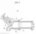
FIG. 2 is a schematic view illustrating a fuel reformer; and
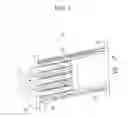
FIG. 3 is a schematic view illustrating a heat transfer portion of a fuel reformer.
The drawings described herein are for illustration purposes only and are not intended to limit the scope of the present disclosure in any way.
DETAILED DESCRIPTION
The following description is merely exemplary in nature and is not intended to limit the present disclosure, application, or uses. It should be understood that throughout the drawings, corresponding reference numerals indicate like or corresponding parts and features.
As those skilled in the art would realize, the described forms may be modified in various different ways, all without departing from the spirit or scope of the present disclosure.
Further, in exemplary forms, since like reference numerals designate like elements having the same configuration, a first exemplary form is representatively described, and in other exemplary forms, only configurations different from the first exemplary form will be described.
The drawings are schematic, and are not illustrated in accordance with a scale. Relative dimensions and ratios of portions in the drawings are illustrated to be exaggerated or reduced in size for clarity and convenience, and the dimensions are just exemplified and are not limiting. In addition, same structures, elements, or components illustrated in two or more drawings use same reference numerals for showing similar features. It will be understood that when an element such as a layer, film, region, or substrate is referred to as being “on” another element, it can be directly on the other element or intervening elements may also be present.
The exemplary form of the present disclosure shows an exemplary form of the present disclosure in detail. As a result, various modifications of the drawings will be expected.
Now, a fuel reforming system as an exemplary form of the present disclosure will be described with reference to FIG. 1.
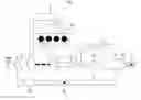
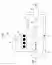
FIG. 1 is a schematic view illustrating a fuel reforming system in one form of the present disclosure.
Referring to FIG. 1, a reforming system includes an engine 10, an intake line 5, an exhaust line 15, a fuel reformer 20, and a catalyst 30.
The engine 10 burns air/fuel mixture in which fuel and air are mixed so as to convert chemical energy into mechanical energy. The engine 10 is connected to an intake manifold so as to receive the air in a combustion chamber, and is connected to an exhaust manifold such that exhaust gas generated in combustion process is gathered in the exhaust manifold and is discharged to outside of the engine. An injector is mounted in the combustion chamber so as to inject the fuel into the combustion chamber.
A diesel engine is exemplified herein, but a lean-burn gasoline engine may be used. In a case that the gasoline engine is used, the air/fuel mixture flows into the combustion chamber through the intake manifold, and a spark plug is mounted at an upper portion of the combustion chamber. In a case that the gasoline engine is used, the air/fuel mixture flows into the combustion chamber through the intake manifold, and a spark plug is mounted at an upper portion of the combustion chamber.
In addition, the engines having various compression ratios. For example, a compression ratio may be lower than or equal to approximately 16.5.
The intake line 5 is connected to an entrance of the engine 10 to supply reformed gas and air to the engine 10, and the exhaust line 15 is connected to an exit of the engine 10 to circulate exhaust gas exhausted from the engine 10.
A portion of the exhaust gas discharged from the engine is supplied to the engine 10 through the EGR line 17. Also, the EGR line 17 is connected to the intake manifold so that combustion temperature is controlled by mixing a portion of the exhaust gas with air. This combustion temperature control is conducted by adjusting exhaust gas amount supplied to the intake manifold. Accordingly, EGR valve 26 adjusting flow rate of the reformed gas may be installed at the EGR line 17.
An exhaust gas recirculation system realized by the EGR line 17 supplies a portion of the exhaust gas to the intake system and inflows to a combustion chamber when an amount of the nitrogen oxide needs to be reduced according to driving condition. Then, the supplied exhaust gas, as inert gas of which volume is not changed, depresses density of the air/fuel mixture, and flame transmitting speed is reduced during combustion of the fuel. Therefore, a combustion speed of the fuel is reduced, and an increase of the combustion temperature is reduced such that generation of the nitrogen oxide decreases.
A fuel reformer 20 is provided at an EGR line 17 diverging from the exhaust line 15, and mixes the EGR gas, which is diverging from the exhaust gas and passing through the EGR line 17, with the fuel and reforms the fuel mixed in the EGR gas.
The catalyst 30 is disposed at the exhaust line 15 and purifies nitrogen oxide included in the exhaust gas at a front end of the fuel reformer 20.
The catalyst 30 may include a lean NOx trap (LNT) which traps the nitrogen oxide included in the exhaust gas in a lean condition and desorbs the trapped nitrogen in a rich condition, and restores the nitrogen oxide included in the exhaust gas or the desorbed nitrogen oxide. The LNT may oxidize carbon monoxide (CO) and hydrocarbon (HC) included in the exhaust gas. Here, it should be understood that the hydrocarbon is used to imply compound including carbon and hydrogen in exhaust gas and fuel.
Also, the catalyst 30 may include a selective catalytic reducer (SCR) restoring the nitrogen oxide included in the exhaust gas by using reducing agent. The reducing agent may be urea injected from an injection module.
In one form, the fuel reforming may further include a compressor 6 connected to the intake line 5 and compresses the reformed gas and air to supply to the engine 10, and a turbine 7 which is connected to the exhaust line 15 and rotated by the exhaust gas to generate power.
Also, the reforming system may include an intercooler 8 connected to the compressor 6. Cooling air and reformed gas flow into the intake line 5 of the engine 10 again, and a throttle valve 9 adjusts a flow rate of the air and reformed gas.
An exhaust pressure control valve 32 adjusting a flow rate of the exhaust gas may be provided at a rear end of the catalyst 30 in the exhaust line 15.
Meanwhile, an EGR valve 26 adjusting a flow rate of the reformed gas, and an EGR cooler 25 which is disposed at a rear end of the EGR valve 26 and cools the reformed gas may be installed at the EGR line 17.
Here, the fuel reformer 20 may be disposed at a front portion of the EGR cooler 27 in the EGR line 17.
FIG. 2 is a schematic view illustrating a fuel reformer in one exemplary form of the present disclosure, and FIG. 3 is a schematic view illustrating a heat transfer portion of a fuel reformer as an exemplary form of the present disclosure.
Referring to FIG. 2, the fuel reformer 20 includes a housing 21, a mixing portion 22 being a space for mixing the fuel supplied from outside with the EGR gas, a fuel injector 23 installed at one side of the housing 21 and supplying the fuel to the mixing portion 22, an EGR pipe 24 connected to the mixing portion 22 in which the EGR gas flows, a heat transfer portion A installed at a rear end of the mixing portion 22, and a reforming catalyst portion 27 provided at a rear end of the heat transfer portion A. The reforming catalyst portion 27 reforms the fuel and EGR gas mixed in the mixing portion 22.
Referring to FIG. 3, the heat transfer portion A includes a penetration member 28, an exhaust gas inlet 31 and an exhaust gas outlet 33.
The penetration member 28 has a plurality of penetration holes configured to circulate the fuel and EGR gas mixed in the mixing portion 22 toward the reforming catalyst portion 27.
The exhaust gas flows in the heat transfer portion A through the exhaust gas inlet 31 and flows out through the exhaust gas outlet 33. The exhaust gas flowed in the heat transfer portion A flows through the plurality of penetration holes formed at the penetration member 28 to transfer exhaust heat of the exhaust gas to the mixed fuel and EGR gas.
As shown in FIG. 3, the exhaust gas may be flowed in and out in a direction crossing to lengthwise direction of the penetration holes, and the exhaust gas may flows around the penetration holes to transfer exhaust heat to the fuel and EGR gas flowing through the penetration holes.
By this heat transfer structure, the exhaust heat is transferred to the fuel and EGR gas before the fuel and EGR gas flow in the reforming catalyst portion 27, therefore temperature of the fuel and EGR gas is sufficiently raised to a sufficient activation temperature of reforming catalyst.
Like this, a heat transfer structure of mixed gas and exhaust gas in a fuel reformer is provided to attain sufficient activation temperature of reforming catalyst for reforming reaction, therefore increasing generation of hydrogen and improves reforming efficiency.
While this present disclosure has been described in connection with what is presently considered to be practical exemplary forms, it is to be understood that the present disclosure is not limited to the disclosed forms. On the contrary, it is intended to cover various modifications and equivalent arrangements included within the spirit and scope of the present disclosure.
DESCRIPTION OF SYMBOLS
| 5: intake line | 6: compressor | |
| 7: turbine | 8: intercooler | |
| 9: throttle valve | 10: engine | |
| 15: exhaust line | 17: EGR line | |
| 20: reformer | 21: housing | |
| 22: mixing portion | 23: fuel injector | |
| 24: EGR pipe | 25: EGR cooler | |
| 26: EGR valve | 27: reforming catalyst portion | |
| 28: penetration member | 30: catalyst | |
| 32: exhaust pressure control valve | 33: exhaust gas outlet | |
Claims
What is claimed is:1. A fuel reforming system, comprising:
an engine configured to combust reformed gas and to generate mechanical power;
an intake line connected to the engine and configured to supply the reformed gas and air to the engine;
an exhaust line connected to the engine and configured to circulate exhaust gas discharged from the engine;
a fuel reformer provided at an exhaust gas recirculation (EGR) line diverging from the exhaust line, the EGR line diverting a portion of the exhaust gas as EGR gas, the fuel reformer configured to mix the EGR gas with the fuel and to reform the fuel mixed in the EGR gas; and
a catalyst disposed at the exhaust line and configured to purify nitrogen oxide included in the exhaust gas at a front end of the fuel reformer.
2. The fuel reforming system of claim 1, wherein the fuel reformer includes:
a housing;
a mixing portion provided in the housing and being a space configured to mix the fuel supplied from outside and the EGR gas;
a fuel injector installed at one side of the housing and configured to supply the fuel to the mixing portion;
an EGR pipe connected to the mixing portion and configured to flow the EGR gas;
a heat transfer portion installed at a rear end of the mixing portion and configured to increase a temperature of the mixed fuel and EGR gas by heat of the exhaust gas; and
a reforming catalyst portion provided at a rear end of the heat transfer portion and configured to reform the mixed fuel and EGR gas.
3. The fuel reforming system of claim 2, wherein the heat transfer portion includes:
a penetration member having a plurality of penetration holes configured to circulate the fuel and EGR gas mixed in the mixing portion toward the reforming catalyst portion; and
an exhaust gas inlet and an exhaust gas outlet through which exhaust gas flows in and out such that the exhaust gas circulates around the plurality of penetration holes.
4. The fuel reforming system of claim 1, further comprising:
a compressor connected to the intake line and configured to compress the reformed gas and air to supply to the engine; and
a turbine connected to the exhaust line and configured to be rotated by the exhaust gas to generate power.
5. The fuel reforming system of claim 1, wherein
the catalyst includes a lean NOx trap (LNT) configured to trap the nitrogen oxide included in the exhaust gas in a lean condition and to desorb the trapped nitrogen in a rich condition, the LNT configured to restore the nitrogen oxide included in the exhaust gas or the desorbed nitrogen oxide.
6. The fuel reforming system of claim 1, wherein
the catalyst includes a selective catalytic reducer (SCR) configured to restore the nitrogen oxide included in the exhaust gas by using a reducing agent.
7. The fuel reforming system of claim 1, wherein
an EGR valve configured to adjust a flow rate of the reformed gas, and
an EGR cooler disposed at a rear end of the EGR valve and configured to cool the reformed gas are both installed at the EGR line.
8. The fuel reforming system of claim 7, wherein
the reformer is installed at a front portion of the EGR cooler in the EGR line.
Images & Drawings included:
Sources:
- United States Patent and Trademark Office - verify current appl. status at the USPTO↗
Similar patent applications:
- » 20050022450
Reformer system, a method of producing hydrogen in the reformer system, and a method of using the reformer system - » 20190273275
Systems and methods for forming a liquid mixture having a predetermined mix ratio and reforming systems, reforming methods, fuel cell systems, and fuel cell methods that utilize the liquid mixture - » 10472983
Carbon monoxide removal method, operating method for fuel reforming system, carbon monoxide remover, fuel reforming system having the carbon monoxide remover, and filter - » 20090297898
REFORMING SYSTEM, METHOD FOR OPERATING A REFORMING SYSTEM AND FUEL CELL SYSTEM - » 20050221132
Rubber composition for fuel reforming system and rubber hose for fuel reforming system using the rubber composition - » 20120272575
FUEL REFORMING SYSTEM AND CONTROL METHOD OF FUEL REFORMING SYSTEM - » 20140053465
Gasification furnace, gasification system, reformer and reforming system - » 20130040215
FUEL CELL SYSTEM, REFORMER SYSTEM, AND METHOD FOR DRIVING FUEL CELL SYSTEM - » 20160193584
Gasification furnace, gasification system, reformer and reforming system - » 20090260592
Fuel ignition system, fuel igniting method, fuel reforming system and fuel reforming method, for internal combustion engine
Recent applications in this class:
- » 20250290439 2025-09-18
DESULFURIZATION METHOD - » 20250264047 2025-08-21
POST-PROCESSING SYSTEM - » 20250250919 2025-08-07
ROBUST CONTROL SYSTEMS AND METHODS OF CATALYST TEMPERATURE STABILITY WITH HEATER ASSISTANCE - » 20250188860 2025-06-12
DIESEL EXHAUST FLUID TANK CONDUIT CONNECTED TO AIR COMPRESSOR AND METHOD - » 20250154888 2025-05-15
DECOMPOSITION CHAMBER WITH GUIDE SWIRL MIXER - » 20250146433 2025-05-08
CATALYTIC PARTIAL WALL-FLOW FILTER - » 20250101898 2025-03-27
ULTRA-COMPACT POST-PROCESSING SYSTEM, SUPERCHARGER ASSEMBLY AND ENGINE - » 20250101897 2025-03-27
SELECTIVE CATALYTIC REDUCTION (SCR) SYSTEM AND ENGINE - » 20250092809 2025-03-20
Heater control in heavy-duty motor vehicle engines - » 20250052182 2025-02-13
EXHAUST STRUCTURE AND INJECTOR ATTACHMENT MEMBER
Recent applications for this Assignee:
- » 20250293967 2025-09-18
VEHICLE CONTROL APPARATUS AND METHOD THEREOF - » 20250293557 2025-09-18
MOTOR WITH A COOLING STRUCTURE - » 20250293373 2025-09-18
BATTERY ASSEMBLY - » 20250293361 2025-09-18
FUEL CELL POWER GENERATION MODULE - » 20250293308 2025-09-18
ELECTRODE ASSEMBLY AND ALL-SOLID STATE BATTERY INCLUDING THE SAME - » 20250292638 2025-09-18
SYSTEM AND METHOD FOR MONITORING POWER OF A VEHICLE - » 20250292590 2025-09-18
METHOD AND APPARATUS FOR CONTEXT-RECOGNITION OBJECT ACTION PREDICTION AND PATH PLANNING FOR AUTONOMOUS VEHICLES BASED ON PEDESTRIAN MOTION PREDICTION - » 20250290600 2025-09-18
PRESSURE VESSEL - » 20250289441 2025-09-18
METHOD AND APPARATUS FOR CALIBRATING ORIENTATION ANGLE OF VEHICLE SENSOR - » 20250289422 2025-09-18
SYSTEM AND METHOD FOR GENERATING EMERGENCY COLLISION AVOIDANCE STRATEGY FOR A VEHICLE