Saddle and hook system
US20180163704A1
2018-06-14
15/106,336
2014-12-18
✅ Patent granted
US 10,167,852 B2
2019-01-01
WO; PCT/NL2014/050875; 20141218
WO; WO2015/093950; 20150625
Kyle Armstrong
N.V. Nederlandsch Octrooibureau | Tamara C. Stegmann | Lindsey A. Auerbach
2035-08-21
Abstract:
The invention relates to a pile upending system for upending a pile such as a monopile for the foundation of offshore wind turbines, the pile upending system comprising;
-
- a pivotally mounted pile support frame having a seat for engaging an outside wall of a pile, the pile support frame being pivotable around a support frame axis of rotation for allowing the seat to support the pile during upending,
- a cable system for supporting an, in use outboard, end of a pile, comprising one or more tensioned or tensionable cables having an outboard end provided with a hoisting member for supporting the outboard end of the pile during upending of said pile,
- an outboard support system comprising a frame member for, in use, extending outboard and supporting the hoisting member of the cable system,
wherein the outboard support system is arranged with respect to the pile support frame such that the frame member extends transverse with respect to the support frame axis of rotation for arranging the hoisting member at a distance from the seat and aligned with the seat such that a pile may engage the hoisting member upon longitudinal movement of the pile along the seat.
Assignee:
- IHC Holland IE B.V. 93 🇳🇱 Sliedrecht, Netherlands
- IHC Holland IE B.V. 4 🇳🇱 Sliedrecht, OT, Netherlands
Applicant:
Interested in similar patents?
Get notified when new applications in this technology area are published.
Classification:
F03D13/20 IPC
Assembly, mounting or commissioning of wind motors; Arrangements specially adapted for transporting wind motor components Arrangements for mounting or supporting wind motors; Masts or towers for wind motors
E02D27/14 » CPC further
Foundations as substructures; Deep foundations; Pile foundations Pile framings, i.e. piles assembled to form the substructure
E02D27/42 IPC
Foundations as substructures; Foundations for special purposes Foundations for poles, masts or chimneys
B63B35/00 IPC
Vessels or similar floating structures specially adapted for specific purposes and not otherwise provided for
F03D13/10 » CPC further
Assembly, mounting or commissioning of wind motors; Arrangements specially adapted for transporting wind motor components Assembly of wind motors; Arrangements for erecting wind motors
F03D13/22 » CPC further
Assembly, mounting or commissioning of wind motors; Arrangements specially adapted for transporting wind motor components; Arrangements for mounting or supporting wind motors; Masts or towers for wind motors Foundations specially adapted for wind motors
E02D27/425 » CPC further
Foundations as substructures; Foundations for special purposes; Foundations for poles, masts or chimneys specially adapted for wind motors masts
B63B35/003 » CPC further
Vessels or similar floating structures specially adapted for specific purposes and not otherwise provided for for transporting very large loads, e.g. offshore structure modules
E02B2017/0047 » CPC further
Artificial islands mounted on piles or like supports, e.g. platforms on raisable legs or offshore constructions ; Construction methods therefor; Methods for placing the offshore structure using a barge
E02B2017/0065 » CPC further
Artificial islands mounted on piles or like supports, e.g. platforms on raisable legs or offshore constructions ; Construction methods therefor; Platforms with supporting legs Monopile structures
E02B2017/0091 » CPC further
Artificial islands mounted on piles or like supports, e.g. platforms on raisable legs or offshore constructions ; Construction methods therefor Offshore structures for wind turbines
F05B2240/95 » CPC further
Components; Mounting on supporting structures or systems offshore
Y02E10/727 » CPC further
Energy generation through renewable energy sources; Wind energy Offshore wind turbines
Y02E10/727 » CPC further
Energy generation through renewable energy sources; Wind energy Offshore wind turbines
F03D13/25 » CPC main
Assembly, mounting or commissioning of wind motors; Arrangements specially adapted for transporting wind motor components; Arrangements for mounting or supporting wind motors; Masts or towers for wind motors specially adapted for offshore installation
E02B17/00 IPC
Artificial islands mounted on piles or like supports, e.g. platforms on raisable legs or offshore constructions ; Construction methods therefor
B63B35/28 » CPC further
Vessels or similar floating structures specially adapted for specific purposes and not otherwise provided for Barges or lighters
B66C1/56 » CPC further
Load-engaging elements or devices attached to lifting or lowering gear of cranes or adapted for connection therewith for transmitting lifting forces to articles or groups of articles by mechanical means; Gripping members engaging only the external or internal surfaces of the articles and applying frictional forces; Internally-expanding grippers for handling hollow articles for handling tubes
Description
The present invention relates to a pile upending system and a method for upending a monopile for the foundation of offshore wind turbines.
GB2226539 A discloses a system for offshore construction work wherein a pile is upended using two cranes one of which cranes is connected via a sling to one end of the pile and the other of which cranes is connected via a sling to two spaced apart connection points on the pile but whose line of action is to the other side of the centre of gravity (c) than the sling. A spreader bar maintains the separation between the connection points during upending. The sling is trained around a sheave so that both slings share the load of the pile equally during upending which is achieved by raising or lowering one sling relative to the other. The three point lift arrangement avoids excessive bending stress on the pile.
It is known to upend a pile offshore wherein an outboard end of a pile rests on a support where around the pile cants. During upending an outboard end is supported by a cable provided with a hook.
Mono-piles, like for supporting a wind turbine, have a large diameter like up to 4 to 6 meters and may weigh hundreds of tonnes. These piles are transported from their production site, to for instance a wind turbine park, in a horizontal stance. These piles are finally used in a vertical stance. Therefore, these piles are upended from a horizontal to a vertical stance on site. This upending is a difficult task since such a pile is a thin walled structure and prone to local bending stresses. In addition, outboard operations in the proximity of the pile may be dangerous for personnel.
SUMMARY OF THE INVENTION
Therefore, the current invention aims to provide a pile upending system which is safer for personnel during operations.
Another object of the invention is to improve a prior pile upending system in that a problem associated therewith is at least partly solved.
Yet another object of the invention is to provide an alternative pile upending system.
According to a first aspect of the invention this is realized with a pile upending system for upending a pile such as a monopile for the foundation of offshore wind turbines, the pile upending system comprising;
-
- a pivotally mounted pile support frame having a seat for engaging an outside wall of a pile, the pile support frame being pivotable around a support frame axis of rotation for allowing the seat to support the pile during upending,
- a cable system for supporting an, in use outboard, end of a pile, comprising one or more tensioned or tensionable cables having an outboard end provided with a hoisting member for supporting the outboard end of the pile during upending of said pile,
- an outboard support system comprising a frame member for, in use, extending outboard and supporting the hoisting member of the cable system,
wherein the outboard support system is arranged with respect to the pile support frame such that the frame member extends transverse with respect to the support frame axis of rotation for arranging the hoisting member at a distance from the seat and aligned with the seat such that a pile may engage the hoisting member upon longitudinal movement of the pile along the seat.
This enables to omit outboard operations by personnel below the pile. This increases safety of the upending operation.
It is noted that in contrast with the invention, FIG. 4 of Dennis Denney ET AL: “Pile-Guiding Tool”, Journal of Petroleum Technology, 7 Mar. 2013 fails to disclose the cable system and therefore the support of the hoisting member of the cable system. Instead Dennis Denney ET AL shows a pivotally mounted pile support frame and an outboard support frame for supporting the end of the pile. In contrast with the current invention, the outboard support frame of Dennis Denney ET AL has a fixed length which offers no flexibility during operation when it is desirable to increase the outboard part of the pile.
Likewise, Manfred Beyer ET AL: “New BAUER Flydrill system drilling monopiles at Barrow Offshore Wind Farm, UK”, BAUER Maschinen GmbH, D-865292 Schrobenhausen, Germany, 21 Oct. 2011 does not disclose the cable system and therefore the support of the hoisting member of the cable system. Instead, Beyer discloses a pile handling system which holds the pile in a frame on deck while upending the pile and a smaller outboard frame guides the pile while being driven.
Remco Löwenthal ET AL: “IHC Handling Systems”, 16 Oct. 2009 discloses a saddle and hook concept with a holding frame and a cable and hook system to hold the end of the pile during upending of the pile. However Löwenthal does not disclose an outboard support system comprising a frame member for, in use, extending outboard and supporting the hoisting member of the cable system. Therefore Löwenthal requires more outboard operations, which is highly undesirable.
GB2394498 (Engineering Business, 28-4-2004), shows a pivoting frame for installing a wind turbine on a structure directly onto a submerged pile using an A-frame that can be moved using a winch-cable system. GB2394498 does not disclose the cable system and therefore the support of the hoisting member of the cable system. Instead, when the structure is in its upright position, thus after upending, a guide or pull wire is attached to the end part of the structure. The guide wire is used to guide the end part of the structure into a pre-positioned foundation, see page 8 lines 7-9.
In an embodiment of the pile upending system according to the invention, a frame member inboard end is coupled with the pile support frame such that the frame member pivots with the pile support frame. This assures that the hoisting member maintains aligned with the seat such that a pile engages the hoisting member upon longitudinal movement of the pile along the seat.
In an embodiment of the pile upending system, the frame member forms a unit with the pile support frame such that the frame member pivots with the pile support frame in unity. This even more assures that the hoisting member maintains aligned with the seat.
In an embodiment of the pile upending system, the pile support frame is pivotally mounted through a spherical bearing that allows the support frame to rotate around the support frame axis of rotation and around axes transverse with respect to the support frame axis of rotation. In this manner, it is possible to optimize the engagement of the seat with the outside wall of a pile when, for example, a crane driver moves the upper end of the pile away from the theoretical upending plane.
In an embodiment, the pile upending system comprises a support frame constraint system for constraining the pile support frame movement in that the support frame is allowed to rotate around a defined axes transverse with respect to the support frame axis of rotation. In this manner, it is possible to support the seat over an increased area rather than alone with the spherical bearing. This way, mechanical stress is reduced.
In an embodiment of the pile upending system, the support frame constraint system extends on both opposite sides of the spherical bearing. This way, the spherical bearing is symmetrically disburdened.
In an embodiment of the pile upending system, the support frame constraint system comprises a cam in cooperation with a slotted hole.
In an embodiment of the pile upending system, the frame member is extendable along its longitudinal axis. This reduces the need for outboard operations by personnel even more.
In an embodiment, the pile upending system comprises a drive system, like a hydraulic cylinder, coupled with the pile support frame for imposing an angular position on the support frame around the support frame axis of rotation.
The invention further relates to a vessel comprising a pile upending system according to the invention.
In an embodiment of the vessel, the support frame axis of rotation extends outboard such that the frame member may take a vertical stance. This reduces the need for outboard operations by personnel even more during the entire upending process.
The invention further relates to a method for upending a pile, in particular a monopile for the foundation of offshore wind turbines, the method comprising;
-
- pivotable supporting the pile for pivoting around a support frame axis of rotation,
- supporting an, in use outboard, end of the pile through a cable system comprising a tensioned or tensionable cable having an outboard end provided with a hoisting member for supporting the outboard end of the pile during upending of said pile,
- supporting the hoisting member of the cable system through an outboard support system comprising a frame member for, in use, extending outboard,
wherein the outboard support system is arranged with respect to the pile support frame such that the frame member extends transverse with respect to the support frame axis of rotation for arranging the hoisting member at a distance from the seat and aligned with the seat such that a pile may engage the hoisting member upon longitudinal movement of the pile along the seat.
The invention further relates to device comprising one or more of the characterising features described in the description and/or shown in the attached drawings.
The invention further relates to method comprising one or more of the characterising features described in the description and/or shown in the attached drawings.
The various aspects discussed in this patent can be combined in order to provide additional advantages.
DESCRIPTION OF THE DRAWINGS
The invention will be further elucidated referring to a preferred embodiment shown in the drawings wherein shown in:
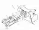
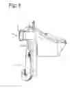
FIG. 1 in perspective view a pile upending system according to the invention;
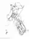
FIG. 2 a top view of the upending system according to FIG. 1;
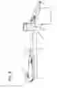
FIG. 3 a side view of the upending system according to FIG. 1;
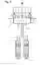
FIG. 4 a front view of the upending system according to FIG. 1; and
FIG. 5 a side view of the upending system according to FIG. 1, wherein the outboard support system takes up a vertical stance.
DETAILED DESCRIPTION OF EMBODIMENTS
The invention will be further elucidated referring to all FIGS. 1-5 wherein a preferred embodiment is shown
There is shown a pile upending system 1 for upending a monopile for the foundation of offshore wind turbines. Such a monopile (not shown) may have a length of tens of meters and weight hundreds of tonnes.
The pile upending system 1 comprises a pile support frame 3 which supports a lower end of the pile during upending. The upper end of the pile is hoisted by a hoisting device (not shown) during upending of the pile. The pile support frame 3 is pivotally mounted such that the pile support frame 3 is able to pivot around a support frame axis of rotation 2. In this manner the pile support frame 3 may accommodate its position to the actual stance of the pile and move with the pile. Here, the pile support frame 3 is pivotally mounted through a spherical bearing known per se. The spherical bearing allows the pile support frame 3 to rotate around the support frame axis of rotation 2 and around axes transverse with respect to the support frame axis of rotation 2.
The pile support frame 3 is provided with a seat 4 which is configured for engaging an outside wall of a pile. During upending, the seat contacts the outside wall of the pile. During upending, the pile support frame 3 supports the pile through the seat 4.
The pile upending system 1 comprises a cable system 11 (partly shown) for supporting an, in use outboard, end of a pile. The cable system 11 is gradually loaded as the pile occupies its vertical stance. The cable system 11 comprises two tensioned or tensionable cables 6. The cables 6 have an outboard end 12 provided with a hoisting member 7. The hoisting member 7 is configured for supporting the outboard end of the pile during upending of said pile. The hoisting member 7 is configured in that the hoisting member 7 is provided with a recess 13 which recess can accommodate a portion of the pile wall such that the pile may be supported.
The pile upending system 1 comprises an outboard support system 5 having a frame member 8 which is configured for, in use, extending outboard and supporting the hoisting member 7 of the cable system 11. The outboard support system 5 is arranged with respect to the pile support frame 3 such that the frame member 8 extends transverse with respect to the support frame axis of rotation 2. In this manner the hoisting member 7 is arranged at a distance from the seat 4 and aligned with the seat 4 such that a pile may engage the hoisting member 7 upon longitudinal movement of the pile along the seat 4. The distance between the hoisting member 7 and the seat 4 is determined by the length of the frame member 8. The frame member inboard end 9 is coupled with the pile support frame 3 such that the frame member pivots with the pile support frame 3. The frame member outboard end 10 supports the, in this case 2, hoisting members 7. In this case, the frame member 8 forms a unit with the pile support frame 3 such that the frame member 8 pivots with the pile support frame 3 in unity.
The pile upending system 1 comprises a support frame constraint system 14a, 14b for constraining the pile support frame movement in that the pile support frame 3 is allowed to rotate around a defined axes transverse with respect to the support frame axis of rotation 2. In this case, the support frame constraint system 14a, 14b extends on both opposite sides of the spherical bearing to disburden the spherical bearing in a symmetrical way. More importantly, in this manner the allowed movement of the heavy pile is constrained.
In use, the pile upending system is mounted on a vessel. The support frame axis of rotation 2 extends outboard and parallel to a side of the vessel such that the frame member 8 may take a vertical stance. A hydraulic cylinder is coupled with the pile support frame 3 for imposing an angular position on the support frame 3 around the support frame axis of rotation 2. The hydraulic cylinder may impose a vertical stance to the support frame 3 as shown in FIG. 3 or a horizontal stance as shown in FIG. 5.
In using the pile upending system 1 the following methods steps are performed
The pile is placed on the seat 4 of the pile support frame for pivoting the pile around a support frame axis of rotation 2. The outboard end of the pile is supported through a cable system 11 comprising a tensioned or tensionable cable 6 having an outboard end provided with a hoisting member 7 for supporting the outboard end of the pile during upending of said pile. The hoisting member 7 of the cable system 11 is supported through an outboard support system 5 comprising a frame member 8 for, in use, extending outboard. The hoisting member 7 is arranged at a distance from the seat 4 and aligned with the seat 4. The pile is moved longitudinally along the seat 4, and finally the pile engages the hoisting member 7 and the outboard end of the pile is supported through the cable system 11.
It will also be obvious after the above description and drawings are included to illustrate some embodiments of the invention, and not to limit the scope of protection. Starting from this disclosure, many more embodiments will be evident to a skilled person which are within the scope of protection and the essence of this invention and which are obvious combinations of prior art techniques and the disclosure of this patent.
Claims
1. A pile upending system for upending a pile such as a monopile for the foundation of offshore wind turbines, the pile upending system comprising;
a pivotally mounted pile support frame having a seat for engaging an outside wall of a pile, the pile support frame being pivotable around a support frame axis of rotation (2) for allowing the seat to support the pile during upending,
a cable system for supporting an, in use outboard, end of a pile, comprising one or more tensioned or tensionable cables having an outboard end provided with a hoisting member for supporting the outboard end of the pile during upending of said pile, and
an outboard support system comprising a frame member for, in use, extending outboard and supporting the hoisting member of the cable system,
wherein the outboard support system is arranged with respect to the pile support frame such that the frame member extends transverse with respect to the support frame axis of rotation for arranging the hoisting member at a distance from the seat and aligned with the seat such that a pile may engage the hoisting member upon longitudinal movement of the pile along the seat.
2. The pile upending system according to claim 1, wherein a frame member inboard end is coupled with the pile support frame such that the frame member pivots with the pile support frame.
3. The pile upending system according to claim 2, wherein the frame member forms a unit with the pile support frame such that the frame member pivots with the pile support frame in unity.
4. The pile upending system according to claim 1, wherein the pile support frame is pivotally mounted through a spherical bearing that allows the support frame to rotate around the support frame axis of rotation and around axes transverse with respect to the support frame axis of rotation.
5. The pile upending system according to claim 1, comprising a support frame constraint system for constraining the pile support frame movement in that the support frame is allowed to rotate around a defined axes transverse with respect to the support frame axis of rotation.
6. The pile upending system according to claim 5, wherein the support frame constraint system extends on both opposite sides of the spherical bearing.
7. The pile upending system according to claim 5, wherein the support frame constraint system comprises a cam in cooperation with a slotted hole.
8. The pile upending system according to a preceding claim, wherein the frame member is extendable along its longitudinal axis.
9. The pile upending system according to claim 1, comprising a drive system, like a hydraulic cylinder, coupled with the pile support frame for imposing an angular position on the support frame around the support frame axis of rotation.
10. A vessel comprising a pile upending system according to claim 1.
11. The vessel according to claim 10, wherein the support frame axis of rotation extends outboard such that the frame member may take a vertical stance.
12. A method for upending a pile, in particular a monopile for the foundation of offshore wind turbines, the method comprising;
pivotable supporting the pile for pivoting around a support frame axis of rotation,
supporting an, in use outboard, end of the pile through a cable system comprising a tensioned or tensionable cable (6) having an outboard end provided with a hoisting member for supporting the outboard end of the pile during upending of said pile,
supporting the hoisting member of the cable system through an outboard support system comprising an frame member for, in use, extending outboard,
wherein the outboard support system is arranged with respect to the pile support frame such that the frame member extends transverse with respect to the support frame axis of rotation for arranging the hoisting member at a distance from the seat and aligned with the seat such that a pile may engage the hoisting member upon longitudinal movement of the pile along the seat.
Images & Drawings included:

Sources:
- United States Patent and Trademark Office - verify current appl. status at the USPTO↗
Recent applications in this class:
- » 20250198386 2025-06-19
High Capacity, Shallow Draft, Ocean-Borne Wind Turbine - » 20250179990 2025-06-05
OFFSHORE WIND TURBINE FOR FRESHWATER PRODUCTION, WIND FARM AND METHOD FOR PRODUCING FRESHWATER - » 20250092857 2025-03-20
FLOATING WIND TURBINE PLATFORM - » 20250003392 2025-01-02
OFFSHORE WIND POWER SINGLE PILE-FRICTION WING COMPOSITE FOUNDATION AND CONSTRUCTION METHOD THEREFOR - » 20240410337 2024-12-12
FLOATING FOUNDATION FOR WIND TURBINE GENERATORS - » 20240309849 2024-09-19
Method for Wet-Towing and Installing a Wind Turbine Bucket Foundation - » 20240301870 2024-09-12
SUBMERGED ASSEMBLY FOR SUPPORTING AN OFFSHORE WIND TURBINE CARRIED ON A MONOPILE - » 20240301869 2024-09-12
OFFSHORE WIND TURBINE ASSEMBLY VESSEL - » 20240167457 2024-05-23
OFFSHORE RENEWABLE ENERGY POWER STATION - » 20240125302 2024-04-18
Offshore vessel, preferably an offshore wind turbine installation vessel, a crane for providing such a vessel, and a method for using such a crane, preferably for upending a monopile
Recent applications for this Assignee:
- » 20250012047 2025-01-09
DISCHARGING SYSTEM FOR A HOPPER - » 20240264095 2024-08-08
SYSTEM FOR MEASURING OF A CONCENTRATION PARAMETER OF A FLOW OF A SOLID/LIQUID MIXTURE - » 20220356666 2022-11-10
Pile-driver assembly and method of using it - » 20220356665 2022-11-10
Pile-driver assembly and method for driving a pile into the ground - » 20220349144 2022-11-03
Pile-driver and method - » 20220242702 2022-08-04
Lifting device and a method of lifting a tubular pile - » 20220178380 2022-06-09
Pump - » 20220074167 2022-03-10
Counterweight Backhoe dredger - » 20210140135 2021-05-13
Template and a method of using the template - » 20210087783 2021-03-25
Cutter head with skirt