Extruder feed system
US20180166727A1
2018-06-14
15/894,101
2018-02-12
✅ Patent granted
US 10,505,213 B2
2019-12-10
-
-
Joseph S Del Sole | Emmanuel S Luk
Gesmer Updegrove LLP
2038-03-07
Abstract:
Extruder feed system. The system includes a pair of spaced-apart, internally and oppositely threaded rotatable elements for receiving and engaging a plastic filament material. Sn electric motor rotates the rotatable elements in opposite directions thereby to drive the filament into a liquefier chamber for subsequent discharge through a nozzle. The system provides very accurate layer-by-layer build up.
Inventors:
- Alfonso Alexander Perez 6 🇺🇸 West Palm Beach, FL, United States
- Christopher Michael Haid 6 🇺🇸 Bolton, MA, United States
- Forrest W. Pieper 6 🇺🇸 Nederland, CO, United States
- Mateo Pena Doll 7 🇺🇸 Elk, CA, United States
Assignee:
- MASSACHUSETTS INSTITUTE OF TECHNOLOGY 7,186 🇺🇸 Cambridge, MA, United States
Applicant:
Interested in similar patents?
Get notified when new applications in this technology area are published.
Classification:
H01M8/188 » CPC main
Fuel cells; Manufacture thereof; Regenerative fuel cells, e.g. redox flow batteries or secondary fuel cells; Regeneration by electrochemical means by recharging of redox couples containing fluids; Redox flow type batteries
B29C48/2528 » CPC further
Extrusion moulding, i.e. expressing the moulding material through a die or nozzle which imparts the desired form; Apparatus therefor; Component parts, details or accessories; Auxiliary operations; Drive or actuation means; Transmission means; Screw supporting means Drive or actuation means for non-plasticising purposes, e.g. dosing unit
B29C48/266 » CPC further
Extrusion moulding, i.e. expressing the moulding material through a die or nozzle which imparts the desired form; Apparatus therefor; Component parts, details or accessories; Auxiliary operations Means for allowing relative movements between the apparatus parts, e.g. for twisting the extruded article or for moving the die along a surface to be coated
B29C48/2886 » CPC further
Extrusion moulding, i.e. expressing the moulding material through a die or nozzle which imparts the desired form; Apparatus therefor; Component parts, details or accessories; Auxiliary operations; Feeding the extrusion material to the extruder in solid form, e.g. powder or granules of fibrous, filamentary or filling materials, e.g. thin fibrous reinforcements or fillers
B29C48/865 » CPC further
Extrusion moulding, i.e. expressing the moulding material through a die or nozzle which imparts the desired form; Apparatus therefor; Component parts, details or accessories; Auxiliary operations; Thermal treatment of the extrusion moulding material or of preformed parts or layers, e.g. by heating or cooling at the nozzle zone Heating
B29C2948/926 » CPC further
Indexing scheme relating to extrusion moulding; Measuring, controlling or regulating; Controlled parameter; Velocity Flow or feed rate
B29C2948/9258 » CPC further
Indexing scheme relating to extrusion moulding; Measuring, controlling or regulating; Controlled parameter Velocity
B29C2948/92571 » CPC further
Indexing scheme relating to extrusion moulding; Measuring, controlling or regulating; Controlled parameter Position, e.g. linear or angular
B29C2948/92904 » CPC further
Indexing scheme relating to extrusion moulding; Measuring, controlling or regulating; Location or phase of control; Extrusion unit Die; Nozzle zone
H01M2250/10 » CPC further
Fuel cells for particular applications; Specific features of fuel cell system Fuel cells in stationary systems, e.g. emergency power source in plant
H01M8/18 IPC
Fuel cells; Manufacture thereof Regenerative fuel cells, e.g. redox flow batteries or secondary fuel cells
B29C48/25 IPC
Extrusion moulding, i.e. expressing the moulding material through a die or nozzle which imparts the desired form; Apparatus therefor Component parts, details or accessories; Auxiliary operations
B29C48/285 IPC
Extrusion moulding, i.e. expressing the moulding material through a die or nozzle which imparts the desired form; Apparatus therefor; Component parts, details or accessories; Auxiliary operations Feeding the extrusion material to the extruder
B65H51/00 » CPC further
Forwarding filamentary material
B29C64/112 » CPC further
Additive manufacturing, i.e. manufacturing of three-dimensional [3D] objects by additive deposition, additive agglomeration or additive layering, e.g. by 3D printing, stereolithography or selective laser sintering; Processes of additive manufacturing using only liquids or viscous materials, e.g. depositing a continuous bead of viscous material using individual droplets, e.g. from jetting heads
B29C48/86 IPC
Extrusion moulding, i.e. expressing the moulding material through a die or nozzle which imparts the desired form; Apparatus therefor; Component parts, details or accessories; Auxiliary operations; Thermal treatment of the extrusion moulding material or of preformed parts or layers, e.g. by heating or cooling at the nozzle zone
B29C48/92 » CPC further
Extrusion moulding, i.e. expressing the moulding material through a die or nozzle which imparts the desired form; Apparatus therefor; Component parts, details or accessories; Auxiliary operations Measuring, controlling or regulating
B29C48/02 » CPC further
Extrusion moulding, i.e. expressing the moulding material through a die or nozzle which imparts the desired form; Apparatus therefor Small extruding apparatus, e.g. handheld, toy or laboratory extruders
B29C48/05 » CPC further
Extrusion moulding, i.e. expressing the moulding material through a die or nozzle which imparts the desired form; Apparatus therefor characterised by the shape of the extruded material at extrusion Filamentary, e.g. strands
B33Y30/00 » CPC further
Apparatus for additive manufacturing; Details thereof or accessories therefor
B29C64/106 » CPC further
Additive manufacturing, i.e. manufacturing of three-dimensional [3D] objects by additive deposition, additive agglomeration or additive layering, e.g. by 3D printing, stereolithography or selective laser sintering; Processes of additive manufacturing using only liquids or viscous materials, e.g. depositing a continuous bead of viscous material
B29C64/393 » CPC further
Additive manufacturing, i.e. manufacturing of three-dimensional [3D] objects by additive deposition, additive agglomeration or additive layering, e.g. by 3D printing, stereolithography or selective laser sintering; Auxiliary operations or equipment; Data acquisition or data processing for additive manufacturing for controlling or regulating additive manufacturing processes
Description
This application claims priority to provisional application Ser. No. 61/863,110 filed on Aug. 7, 2013, the contents of which are incorporated herein by reference.
BACKGROUND OF THE INVENTION
This invention relates to an extruder, and more particulary, to an extruder used in an additive manufacturing device employing a screw drive.
Additive manufacturing devices such as 3-D printers build up an object layer-by-layer by extruding a filament material onto a support surface. The quality of the object produced depends in large measure on tight control of the flow rate of filament material through the extruder in conjunction with control of the X-Y position of the extruder head as it traverses an area to build up a layer.
A prior art extruder system is shown schematically in FIG. 1. Filament material 10 passes through a pinch roller feed system 12 that drives the filament material 10 downwardly into a liquefier chamber 14. Thereafter, filament material is discharged through a nozzle 16 onto a scaffolding 18. The pinch roller system 12 engages the filament material 10 on each side as it drives the filament material into the liquefier chamber 14. The driving force that can be achieved with the arrangement in FIG. 1 is limited. Further, the arrangement shown in FIG. 1 is not as accurate as desired because of step size limitations in motor systems driving the pinch rollers.
It is also known to use an internally threaded nut to drive a filament into a liquefier chamber. In this case, the filament passes thorough an internally threaded nut which, upon rotation, drives the filament material linearly. However, the nut rotation puts an unwanted torque on the filament, causing it to distort as it is driven linearly.
An objet of the present invention is a screw drive employing counter-rotating elements to substantially eliminate the unwanted torque while driving the filament into the extruder.
SUMMARY OF THE INVENTION
The extruder feed system according to the invention includes a pair of spaced-apart, internally and oppositely threaded rotatable elements for receiving and engaging a filament material. A motor is provided for rotating the rotatable elements in opposite directions, thereby to drive the filament into a liquefier chamber for subsequent discharge through a nozzle. In a preferred embodiment, the system includes a gear train driven by the motor to rotate the rotatable elements in opposite directions. A suitable motor is a stepper motor or a DC motor. The filament material may be plastic.
In a preferred embodiment, the gear train includes beveled gears driven by the motor. the gear train may include a belt or cable driven with pulleys.
In yet another embodiment, the system of the invention further includes a control loop for controlling power of the motor, thereby to control the filament material extrusion rate.
BRIEF DESCRIPTION OF THE DRAWING
FIG. 1 is a cross-sectional view of a prior art additive manufacturing extruder system.
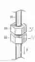
FIG. 2 is a schematic illustration of a pair of counter-rotatable hex nuts for driving a filament material.
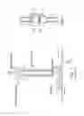
FIG. 3 is a cross-sectional view of an embodiment of the invention disclosed herein utilizing a motor, a flow controller and bevel gears driving the counter-rotating bevel gears.
DESCRIPTION OF THE PREFERRED EMBODIMENT
With reference to FIG. 2, filament material 10 is seen passing through the interior of first and second hex nuts 20 and 22. The hex nut 20 is internally threaded in, for example, a right-handed thread pattern. Similarly, the hex nut 22 is internally threaded to have the opposite direction for the threads, such as a left-handed thread pattern. It is preferred that the diameter of the filament 10 be slightly oversized with respect to the tapped hole through the hex nuts 20 and 22. As can be seen in the figure, the hex nut 20 is rotated in a counterclockwise direction and the hex nut 22 is rotated in a clockwise direction. Because the threads of the counter rotating hex nuts 20 and 22 are oppositely directed, the filament material 10 is driven downwardly in FIG. 2.
Importantly, because the hex nuts 20 and 22 are counter-rotating, material distortion resulting from torque between the two hex nuts is substantially eliminated as the counter-rotating nuts balance out the torque effects.
An embodiment of the present invention is shown in FIG. 3. A frame 30 supports for rotation bevel gears 32, 34 and 36. A motor 38 under the control of a flow controller 40 rotates the bevel gear 32. The bevel gear 32 operatively engages the bevel gears 34 and 36 driving these bevel gears in opposite rotational directions. As will be appreciated, the interior of the bevel gear 34 is threaded in a first sense, such as right-handed, and the bevel gear 36 is internally threaded in the opposite sense such as left-handed. When the motor 38 is activated under control of the flow controller 40, the filament 10 will be driven into a liquefier chamber as shown in FIG. 1. The motor 38 may be a stepper motor or a DC motor. The motor may be a pneumatic motor, internal combustion engine or an AC motor. The arrangement of the motor 38 shown in FIG. 3 assures that the flow rate of filaments 10 material through the system can be precisely controlled.
Those of skill in the art will recognize that separate motors could be used to drive the rotatable elements if desired. It is also noted that the space between the bevel gears 34 and 36 should be made small to minimize distortion of the filament passing through the counter-rotating bevel gears. The gap in FIG. 3 is exaggerated for clarity.
The inventors herein have determined that driving the bevel gears 34 and 36 at the same speed in opposite directions isn't sufficient to ensure a constant extrusion rate due to variabilities to the diameter of the filament 10 and other physical inconsistencies. The inventors have analytically determined that there is a direct relationship between the extrusion rate and the input electrical power to the motor 38 using the screw drive of the invention. In particular, inventors have determined that the extrusion rate Q=kIV. That is to say, filament flow rate Q is linearly proportional to power (IV) on the motor 38 is held constant (that is to say, the product of motor current (I) and motor voltage (V) is held constant). To increase or decrease the flow rate, the motor 38 voltage is controlled via a PWM control on the motor 38 voltage. Thus, filament flow rate is controlled by controlling power to the motor 38. The flow controller 40 may include a conventional control loop employing PID control for example.
It is recognized that modifications and variations of the present invention will be apparent to those of ordinary skill in the art and it is intended that all such modifications and variations be included within the scope of the appended claims.
Claims
1. Extruder feed system comprising:
a pair of spaced-apart, internally and oppositely threaded rotatable elements for receiving and engaging a filament material; and
a motor for rotating the rotatable elements in opposite directions thereby to drive the filament into a liquefier chamber for subsequent discharge through a nozzle.
2. The system of claim 1 further including a gear train driven by the motor to rotate the rotatable elements in opposite directions.
3. The system of claim 1 wherein the motor is a stepper motor.
4. The system of claim 1 wherein the motor is DC motor.
5. The system of claim 2 wherein the gear train includes a beveled gear driven by the motor.
6. The system of claim 1 wherein the rotatable elements are internally threaded hex nuts.
7. The system of claim 1 further including a control loop for controlling power of the motor thereby to control the filament material extrusion rate.
8. the system of claim 1 wherein the motor is a pneumatic motor, internal combustion engine or an AC motor.
9. The system of claim 2 wherein the gear train includes a belt or cable driven with pulleys.
Images & Drawings included:

Sources:
- United States Patent and Trademark Office - verify current appl. status at the USPTO↗
Similar patent applications:
- » 20150086668
Extruder feed system - » 20110002190
Fiber Feed System For Extruder For Use In Filled Polymeric Products - » 20140284834
Universal feeding system for extruders - » 10360766
Direct feed extruder supply system - » 20230226761
EXTRUDER, GRANULE FEED, AND LIQUID ADDITIVE DISPENSER SYSTEM FOR 3D PRINTERS - » 20240246277
CHARGING SYSTEM FOR FEEDING PROCESSING MATERIAL TO AN EXTRUDER SCREW, HAVING AXIALLY EXTENDING RECESSES IN A HOPPER WALL - » 20220143914
CHARGING SYSTEM AND METHOD FOR FEEDING PROCESSING MATERIAL TO AN EXTRUDER SCREW
Recent applications in this class:
- » 20250293280 2025-09-18
FLOW BATTERY - » 20250286097 2025-09-11
CELL FOR POWER GENERATION DEVICE, ASSOCIATED DEVICES AND METHOD - » 20250260040 2025-08-14
FLOW BATTERY WITH THERMAL ACTIVATION - » 20250253376 2025-08-07
Flow Battery with a Dynamic Fluidic Network - » 20250253375 2025-08-07
METHOD FOR OPERATING A REDOX FLOW BATTERY SYSTEM - » 20250233184 2025-07-17
COST-EFFICIENT HIGH ENERGY DENSITY REDOX FLOW BATTERY - » 20250219121 2025-07-03
A METAL ELECTRODE SYSTEM FOR ELECTROCHEMICAL CELLS - » 20250210681 2025-06-26
REDOX FLOW BATTERY - » 20250183343 2025-06-05
DEVICES AND METHODS FOR SIMULTANEOUS MECHANOCHEMICAL AND ELECTROCHEMICAL REACTIONS - » 20250174695 2025-05-29
ELECTROLYTE FOR ORGANIC REDOX FLOW BATTERIES AND ORGANIC REDOX FLOW BATTERIES COMPRISING THE SAME
Recent applications for this Assignee:
- » 20250288624 2025-09-18
LONG-TERM STABILIZATION, FORMULATION AND TABLETING OF LIVE MICROBIAL CELLS - » 20250284856 2025-09-11
GENERALIZABLE END-TO-END AUTONOMOUS DRIVING WITH MULTI-MODAL FOUNDATION MODELS - » 20250283816 2025-09-11
COMPOSITIONS FOR DETECTION OF FLUOROCARBONS AND RELATED ARTICLES, SYSTEMS, AND METHODS - » 20250281931 2025-09-11
High-Throughput Expansion Microscopy, Devices for Use With a Well Plate and Methods for Processing a Sample - » 20250278625 2025-09-04
VISUOMOTOR POLICY LEARNING VIA ACTION DIFFUSION - » 20250275716 2025-09-04
SENSORIZED WEARABLE GARMENT - » 20250275026 2025-08-28
ELECTRICALLY CONDUCTIVE FIREBRICK SYSTEM - » 20250263824 2025-08-21
ADDITIVELY MANUFACTURED OXIDE DISPERSION-STRENGTHENED ALLOY - » 20250261881 2025-08-21
FLEXIBLE ELECTRONICS FOR ANALYTE DETECTION - » 20250257316 2025-08-14
CONTROL OF NITROGEN FIXATION IN RHIZOBIA THAT ASSOCIATE WITH CEREALS