Glued arrangement
US20180169999A1
2018-06-21
15/900,431
2018-02-20
✅ Patent granted
US 11,059,265 B2
2021-07-13
-
-
Catherine A. Simone
Crowell & Moring LLP
2038-07-20
Abstract:
A glued arrangement, preferably for a motor vehicle, is disclosed. The glued arrangement includes a first component, a second component, and at least one adhesive layer for connecting the two components. The adhesive layer includes a central zone and an edge zone that surrounds the central zone where, in the hardened state, the adhesive in the edge zone has a higher elasticity than the adhesive in the central zone.
Assignee:
- BAYERISCHE MOTOREN WERKE AKTIENGESELLSCHAFT 3,338 🇩🇪 Munich, Germany
Applicant:
Interested in similar patents?
Get notified when new applications in this technology area are published.
Classification:
B32B7/04 IPC
Layered products characterised by the relation between layers; Layered products characterised by the relative orientation of features between layers, or by the relative values of a measurable parameter between layers, i.e. products comprising layers having different physical, chemical or physicochemical properties; Layered products characterised by the interconnection of layers Interconnection of layers
B32B37/12 » CPC further
Methods or apparatus for laminating, e.g. by curing or by ultrasonic bonding characterised by using adhesives
B32B38/00 IPC
Ancillary operations in connection with laminating processes
B32B38/0008 » CPC further
Ancillary operations in connection with laminating processes Electrical discharge treatment, e.g. corona, plasma treatment; wave energy or particle radiation
B62D27/026 » CPC further
Connections between superstructure sub-units rigid Connections by glue bonding
B32B2037/1269 » CPC further
Methods or apparatus for laminating, e.g. by curing or by ultrasonic bonding characterised by using adhesives multi-component adhesive
B32B2307/54 » CPC further
Properties of the layers or laminate having particular mechanical properties Yield strength; Tensile strength
B32B2307/542 » CPC further
Properties of the layers or laminate having particular mechanical properties Shear strength
B32B2375/00 » CPC further
Polyureas; Polyurethanes
B32B2605/00 » CPC further
Vehicles
B32B7/12 » CPC further
Layered products characterised by the relation between layers; Layered products characterised by the relative orientation of features between layers, or by the relative values of a measurable parameter between layers, i.e. products comprising layers having different physical, chemical or physicochemical properties; Layered products characterised by the interconnection of layers; Interconnection of layers using interposed adhesives or interposed materials with bonding properties
B29C65/1406 » CPC further
Joining of preformed parts ; Apparatus therefor by heating, with or without pressure using wave energy or particle radiation characterised by the type of electromagnetic or particle radiation Ultraviolet [UV] radiation
B29C65/483 » CPC further
Joining of preformed parts ; Apparatus therefor using adhesives, i.e. using supplementary joining material; solvent bonding characterised by the type of adhesives Reactive adhesives, e.g. chemically curing adhesives
B29C65/485 » CPC further
Joining of preformed parts ; Apparatus therefor using adhesives, i.e. using supplementary joining material; solvent bonding characterised by the type of adhesives; Reactive adhesives, e.g. chemically curing adhesives Multi-component adhesives, i.e. chemically curing as a result of the mixing of said multi-components
B29C65/4835 » CPC further
Joining of preformed parts ; Apparatus therefor using adhesives, i.e. using supplementary joining material; solvent bonding characterised by the type of adhesives; Reactive adhesives, e.g. chemically curing adhesives Heat curing adhesives
B29C65/4845 » CPC further
Joining of preformed parts ; Apparatus therefor using adhesives, i.e. using supplementary joining material; solvent bonding characterised by the type of adhesives; Reactive adhesives, e.g. chemically curing adhesives Radiation curing adhesives, e.g. UV light curing adhesives
B29C65/8215 » CPC further
Joining of preformed parts ; Apparatus therefor; Testing the joint by mechanical methods Tensile tests
B29C66/1122 » CPC further
General aspects of processes or apparatus for joining preformed parts; General aspects dealing with the joint area or with the area to be joined; Particular design of joint configurations particular design of the joint cross-sections; Joint cross-sections comprising a single joint-segment, i.e. one of the parts to be joined comprising a single joint-segment in the joint cross-section; Single lapped joints Single lap to lap joints, i.e. overlap joints
B29C66/3452 » CPC further
General aspects of processes or apparatus for joining preformed parts; General aspects dealing with the joint area or with the area to be joined; Progressively making the joint, e.g. starting from the middle Making complete joints by combining partial joints
B29C66/43 » CPC further
General aspects of processes or apparatus for joining preformed parts; General aspects of joining substantially flat articles, e.g. plates, sheets or web-like materials; Making flat seams in tubular or hollow articles; Joining single elements to substantially flat surfaces; Joining substantially flat articles ; Making flat seams in tubular or hollow articles Joining a relatively small portion of the surface of said articles
B29C66/721 » CPC further
General aspects of processes or apparatus for joining preformed parts characterised by the composition, physical properties or the structure of the material of the parts to be joined; Joining with non-plastics material characterised by the structure of the material of the parts to be joined Fibre-reinforced materials
B29L2031/30 » CPC further
Other particular articles Vehicles, e.g. ships or aircraft, or body parts thereof
B62D29/048 » CPC further
Superstructures, characterised by the material thereof predominantly of synthetic material Connections therefor, e.g. joints
C09J2301/416 » CPC further
Additional features of adhesives in the form of films or foils characterized by the presence of essential components use of irradiation
F16B11/006 » CPC further
Connecting constructional elements or machine parts by sticking or pressing them together, e.g. cold pressure welding by gluing
B32B7/05 » CPC main
Layered products characterised by the relation between layers; Layered products characterised by the relative orientation of features between layers, or by the relative values of a measurable parameter between layers, i.e. products comprising layers having different physical, chemical or physicochemical properties; Layered products characterised by the interconnection of layers; Interconnection of layers the layers not being connected over the whole surface, e.g. discontinuous connection or patterned connection
B32B5/18 » CPC further
Layered products characterised by the non- homogeneity or physical structure, i.e. comprising a fibrous, filamentary, particulate or foam layer; Layered products characterised by having a layer differing constitutionally or physically in different parts characterised by features of a layer of foamed material
C09J5/00 » CPC further
Adhesive processes in general; Adhesive processes not provided for elsewhere, e.g. relating to primers
B62D27/02 IPC
Connections between superstructure sub-units rigid
B29C65/00 IPC
Joining of preformed parts ; Apparatus therefor
B29C65/48 IPC
Joining of preformed parts ; Apparatus therefor using adhesives, i.e. using supplementary joining material; solvent bonding
B29C65/14 IPC
Joining of preformed parts ; Apparatus therefor by heating, with or without pressure using wave energy or particle radiation
B29C65/82 IPC
Joining of preformed parts ; Apparatus therefor Testing the joint
F16B11/00 IPC
Connecting constructional elements or machine parts by sticking or pressing them together, e.g. cold pressure welding
B62D29/04 IPC
Superstructures, characterised by the material thereof predominantly of synthetic material
Description
CROSS REFERENCE TO RELATED APPLICATIONS
This application is a continuation of PCT International Application No. PCT/EP2016/066878, filed Jul. 15, 2016, which claims priority under 35 U.S.C. § 119 from German Patent Application No. 10 2015 215 978.7, filed Aug. 21, 2015, the entire disclosures of which are herein expressly incorporated by reference.
BACKGROUND AND SUMMARY OF THE INVENTION
The present invention relates to a glued arrangement, preferably for a motor vehicle. Specifically, the adhesive layer between two components is described.
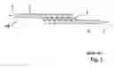
FIG. 3 shows in purely schematic representation a previously known glued arrangement 100 with two components 3, 4 and an adhesive layer 2 for the connecting of the two components 3, 4. The arrangement 100 is loaded with a force 7 to test the tensile shear strength. In order to discuss the problems which occur, the components 3, 4 and the adhesive layer 2 have been divided into individual finite elements.
Especially under tensile and compressive stresses, high peak values occur at the edge of the adhesive layer 2, which may result in a failure. Due to the use of structural adhesives with high E modulus in connection with high peak stresses, the corresponding adhesive layers have a critical place at the edge of the bonding. Since this represents a limiting factor, the glue connection cannot be scaled at will and its load-bearing capacity increases less than proportionately to the overlapping length. By increasing the overlapping length and consequently also the quantity of adhesive, therefore only a slightly larger load-bearing capacity is achieved. The result is contradictory demands on the glue connection, which are compensated by additional mechanical force closure connections. Consequently, material and installation expense and the associated costs are relatively high. Moreover, the failure of the glue connection may lead to safety-critical problems of the overall structure.
One problem which the present invention solves is to indicate a glued arrangement, preferably for a motor vehicle, which enables a durable connection with easy production and efficient use of the adhesive quantity.
Thus, the problem is solved by a glued arrangement. The glued arrangement is advantageously used in a motor vehicle. This may involve, for example, glued components of the body or the chassis. The arrangement according to the invention includes a first component and a second component, as well as at least one adhesive layer for connecting the two components. The two components are advantageously made of fiber-reinforced plastic. Alternatively, the components may also be made from simple plastic or metal. It is also provided that the two components are made of different materials. The two components are joined together directly with the adhesive layer, so that both components touch the adhesive layer.
According to the invention, it is provided that the adhesive layer includes a central zone and an edge zone enclosing the central zone. Both components are in contact with both the edge zone and the central zone. In the hardened state of the adhesive, the edge zone has a greater elasticity than the central zone. Thus, the E modulus in the edge zone is less than the E modulus in the central zone.
Due to the different elasticities in the edge zone and in the central zone, the peak stresses are reduced at the edge of the adhesive layer on account of the uniform distribution of the stress over the glue surface. Moreover, its load bearing ability is improved, which has a positive effect on the operating strength and the usage level of the material consumption. Therefore, depending on the application, the use of additional force-locking connectors may be unnecessary. The result is less weight for the arrangement, a reduced material and assembly expense and the associated costs are lower. Furthermore, almost any desired scaling of the glue connection is possible through the overlapping length. Because of better adhesion, there is greater security against failure under peak stresses. Consequently, the likelihood of a failure of the overall structure is also reduced and the safety of the persons involved is increased.
Basically, any desired adhesives may be used for the adhesive layer, both in the central zone and in the edge zone. For example, binary adhesives (with binder and hardener), thermal hardening adhesives, or UV-hardening adhesives can be used in this case.
According to a preferred embodiment, it is provided that the central zone and the edge zone consist of two different adhesives. In this case, the proper adhesives can be chosen for the particular application, so that in the hardened state the elasticity in the edge zone is greater than in the central zone. For example, a binary adhesive based on polyurethane is used for the central zone. The adhesives for the edge zone are elastic adhesives (low rigidities of 2 to 50 MPa or medium rigidities of 50 to 200 MPa) with large breaking elongation or deformation, in order to reduce possibly high peak stress or high strain in the edge zone. For example, disk adhesives may be used here.
Alternatively to the use of two different adhesives for the central zone and the edge zone, the same adhesive may also be used, with the central zone and the edge zone having different degrees of hardening.
The method of different hardening in the edge zone and in the central zone can also be used when two different adhesives are used in the zones.
Preferably, less hardener and/or a different hardener is used for the edge zone. In addition or alternatively, it is possible to heat the central zone more intensively and/or irradiate it more intensively with UV light, so that a stronger hardening occurs here. It is also provided, for example, to insert thermal conduction elements or light guides in the adhesive layer in order to influence the hardening in a local manner.
Depending on the loading which occurs for the arrangement, the edge zone is formed fully around the central zone or only at certain sites. It is preferably provided that the edge zone is arranged at least 30%, preferably at least 50%, especially preferably at least 70% around the periphery of the central zone. An especially preferred embodiment calls for a full arrangement (100%) of the edge zone.
Preferably, it is provided that the edge zone be directly adjacent to the central zone. Thus, there is no gap between the edge zone and the central zone.
The edge zone should be sufficiently large to enable an elastic glue connection in the edge region. However, a sufficient area should also be available for the central zone and thus for the relatively hard region of the adhesive layer. A quotient Q (Q=F/G) is defined, with the area F of the edge zone and the total area G of the adhesive layer (edge zone+central zone). Advantageously, the lower limit of the quotient is at least 0.01, preferably at least 0.05. The upper limit of the quotient Q is advantageously at most 0.8, preferably at most 0.4, especially preferably at most 0.3.
The E modulus of the central zone is advantageously at least 120%, preferably at least 150%, especially preferably at least 200% of the E modulus of the edge zone.
The two glued components are advantageously sheetlike components which are glued together in an overlap region. Thus, a relevant loading of the adhesive layer is a shear loading. The tensile shear strength of the central zone is advantageously at least 120%, preferably at least 150%, especially preferably at least 200% of the tensile shear strength of the edge zone. In particular, the tensile shear strength here is determined according to DIN EN 1465:2009-07.
The invention furthermore comprises a method for making the just described arrangement. The method comprises the following steps:
(i) application of the adhesive layer with the central zone and the edge zone surrounding the central zone. In particular, the adhesives for both zones are applied before the components are placed one on top of the other. The edge zone is thus advantageously not injected subsequently between the two components.
(ii) Use of different adhesives for the central zone and the edge zone and/or different hardening of the adhesive in the central zone and the edge zone so that the edge zone has a greater elasticity than the central zone.
For the different hardening in the edge zone and in the central zone, a different quantity of hardener and/or a different hardener is advantageously used. In addition or alternatively, the edge zone and the central zone may be heated differently. In addition or alternatively, it is provided that the edge zone and the central zone are treated differently with UV light, in order to achieve different hardening in this way.
The invention furthermore comprises a motor vehicle having at least one of the specified glued arrangements. The two components in this case are in particular fiber-reinforced plastics which are used in the body or the chassis.
Other objects, advantages and novel features of the present invention will become apparent from the following detailed description of one or more preferred embodiments when considered in conjunction with the accompanying drawings.
Further details, features and benefits of the invention will emerge from the following specification and the drawings.
BRIEF DESCRIPTION OF THE DRAWINGS
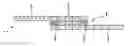
FIG. 1 is a schematic cross section view of a glued arrangement of the invention according to an exemplary embodiment;
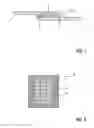
FIG. 2 is a schematic top view of the adhesive layer of the glued arrangement of the invention according to the exemplary embodiment; and
FIG. 3 is an arrangement according to the prior art.
DETAILED DESCRIPTION OF THE DRAWINGS
FIGS. 1 and 2 show an arrangement 1 with a first component 3 and a second component 4. The two components 3, 4 overlap. In the overlap region, the two components 3, 4 are joined together by means of an adhesive layer 2.
Merely for the explanation of the invention, the components 3, 4 and the adhesive layer 2 in the Figures have been divided into finite elements.
FIG. 1 shows a schematic cross section view of the arrangement 1. FIG. 2 shows a schematic top view of the adhesive layer 2.
The adhesive layer 2 is divided into a central zone 5 and an edge zone 6. The edge zone 6 in the example shown fully surrounds the central zone 5. The adhesive used in the central zone 5 has a lesser elasticity than in the edge zone 6. As already described, different adhesives may be used in the central zone 5 and in the edge zone 6 for this effect. Alternatively or additionally, the adhesives in the central zone 5 and in the edge zone 6 may be hardened differently.
As is shown by a consideration of the arrangement 100 of the prior art in FIG. 3, under tensile loading the greatest stresses occur in the edge zone 6. Since according to the invention a relatively elastic bonding has been chosen in the edge zone 6, these peak stresses can be absorbed without failure of the components.
LIST OF REFERENCE NUMBERS
- 1 glued arrangement
- 2 adhesive layer
- 3 first component
- 4 second component
- 5 central zone
- 6 edge zone
- 7 force
- 100 glued arrangement according to the prior art
The foregoing disclosure has been set forth merely to illustrate the invention and is not intended to be limiting. Since modifications of the disclosed embodiments incorporating the spirit and substance of the invention may occur to persons skilled in the art, the invention should be construed to include everything within the scope of the appended claims and equivalents thereof.
Claims
What is claimed is:1. A glued arrangement, comprising:
a first component;
a second component; and
an adhesive layer, wherein the adhesive layer connects the first component to the second component;
wherein the adhesive layer includes a central zone and an edge zone that encloses the central zone and wherein, in a hardened state, a first adhesive in the edge zone has a greater elasticity than a second adhesive in the central zone.
2. The glued arrangement as claimed in claim 1, wherein the first adhesive and the second adhesive are different adhesives or wherein the first adhesive and the second adhesive are a same adhesive.
3. The glued arrangement as claimed in claim 1, wherein the central zone is more hardened than the edge zone.
4. The glued arrangement as claimed in claim 2, wherein die central zone is more hardened than the edge zone.
5. The glued arrangement as claimed in claim 1, wherein the edge zone is disposed at least 30% around a periphery of the central zone.
6. The glued arrangement as claimed in claim 1, wherein the edge zone is directly adjacent to the central zone.
7. The glued arrangement as claimed in claim 1, wherein for a quotient (Q=F/G) of an area (F) of the edge zone and a total area (G) of the adhesive layer, a lower limit of the quotient is at least 0.01 and an upper limit of the quotient is at most 0.8.
8. The glued arrangement as claimed in claim 2, wherein for a quotient (Q=F/G) of an area (F) of the edge zone and a total area (G) of the adhesive layer, a lower limit of the quotient is at least 0.01 and an upper limit of the quotient is at most 0.8.
9. The glued arrangement as claimed in claim 3, wherein for a quotient (Q=F/G) of an area (F) of the edge zone and a total area (G) of the adhesive layer, a lower limit of the quotient is at least 0.01 and an upper limit of the quotient is at most 0.8.
10. The glued arrangement as claimed in claim 1, wherein an E modulus of the central zone is at least 120% of an E modulus of the edge zone.
11. The glued arrangement as claimed in claim 2, wherein an E modulus of the central zone is at least 120% of an E modulus of the edge zone.
12. The glued arrangement as claimed in claim 3, wherein an E modulus of the central zone is at least 120% of an E modulus of the edge zone.
13. The glued arrangement as claimed in claim 7, wherein an E modulus of the central zone is at least 120% of an E modulus of the edge zone.
14. The glued arrangement as claimed in claim 1, wherein a tensile shear strength of the central zone is at least 120% of a tensile shear strength of the edge zone.
15. The glued arrangement as claimed in claim 2, wherein a tensile shear strength of the central zone is at least 120% of a tensile shear strength of the edge zone.
16. The glued arrangement as claimed in claim 3, wherein a tensile shear strength of the central zone is at least 120% of a tensile shear strength of the edge zone.
17. The glued arrangement as claimed in claim 7, wherein a tensile shear strength of the central zone is at least 120% of a tensile shear strength of the edge zone.
18. The glued arrangement as claimed in claim 10, wherein a tensile shear strength of the central zone is at least 120% of a tensile shear strength of the edge zone.
19. A method for making a glued arrangement, comprising the act of:
connecting a first component to a second component via an adhesive layer;
wherein the adhesive layer includes a central zone and an edge zone that encloses the central zone, wherein, in a hardened state, a first adhesive in the edge zone has a greater elasticity than a second adhesive in the central zone, and wherein the first adhesive and the second adhesive are different adhesives and/or wherein the first adhesive and the second adhesive have different hardenings.
20. The method as claimed in claim 19, wherein for the different hardenings, a different quantity of a hardener is used and/or the edge zone and the central zone are heated differently and/or the edge zone and the central zone are treated differently with ultraviolet light.
Images & Drawings included:
Sources:
- United States Patent and Trademark Office - verify current appl. status at the USPTO↗
Similar patent applications:
Recent applications in this class:
- » 20190315091 2019-10-17
Composite paneling having multiple facesheets and a core - » 20190255808 2019-08-22
Impact-resistant pad - » 20190143640 2019-05-16
ABSORBENT LAMINATE WITH BOND PATTERN AND METHODS OF MAKING AND USING THE SAME - » 20190118509 2019-04-25
Method and apparatus for producing a breathable web and relative web - » 20180281345 2018-10-04
Method for Manufacturing a Welded Component and Use of the Component - » 20170066219 2017-03-09
Three-dimensional composite tape, method and apparatus for its production - » 20160236442 2016-08-18
Chub packaging webs with enhanced puncture resistance - » 20160221302 2016-08-04
CONFIGURABLE COMPOSITES - » 20160207282 2016-07-21
Composite Panel for Joining with a Clinch Joint and Method of Forming a Clinch Joint - » 20160129670 2016-05-12
Method for manufacturing structure and structure
Recent applications for this Assignee:
- » 20250236179 2025-07-24
METHOD FOR OPERATING A BRAKE CONTROL SYSTEM, BRAKE CONTROL SYSTEM, COMPUTER PROGRAM, AND COMPUTER-READABLE STORAGE MEDIUM - » 20250109792 2025-04-03
Mounting assembly for a coupler mechanism of a motor vehicle - » 20250077042 2025-03-06
Method for increasing safety during the operation of a device - » 20250042351 2025-02-06
Arrangement for Holding a Sidewall Element on a Bodyshell Part of a Vehicle, Bracket and Vehicle - » 20250026428 2025-01-23
Handlebar Assembly for a Motor Vehicle, and Motor Vehicle Having a Handlebar Assembly of This Kind - » 20250020305 2025-01-16
Decorative element for a motor vehicle, and production method for a decorative element - » 20250001843 2025-01-02
Motor Vehicle With a Side Door - » 20240426445 2024-12-26
Motor Vehicle Lighting Module - » 20240383554 2024-11-21
Leaning vehicle - » 20240383416 2024-11-21
Motor vehicle having a plurality of control devices which provide different vehicle functions in the motor vehicle and method for configuring the control devices and control device