LED current ramping method for optical mouse
US20180173324A1
2018-06-21
15/382,750
2016-12-19
✅ Patent granted
US 10,042,434 B2
2018-08-07
-
-
Duc Q Dinh
Winston Hsu
2036-12-19
Abstract:
An LED current ramping method for an optical mouse includes: determining a speed of the optical mouse; setting control bits according to the determined speed; sending the control bits to a digital circuit of the mouse; and decoding the control bits to selectively open and close switches in a constant current LED driver of the mouse to adjust a current according to the speed.
Assignee:
- PIXART IMAGING (PENANG) SDN. BHD. 35 🇲🇾 PENANG, Malaysia
Applicant:
Interested in similar patents?
Get notified when new applications in this technology area are published.
Classification:
G09G2310/066 » CPC further
Command of the display device; Details of flat display driving waveforms Waveforms comprising a gently increasing or decreasing portion, e.g. ramp
G06F3/0312 » CPC main
Input arrangements for transferring data to be processed into a form capable of being handled by the computer; Output arrangements for transferring data from processing unit to output unit, e.g. interface arrangements; Input arrangements or combined input and output arrangements for interaction between user and computer; Arrangements for converting the position or the displacement of a member into a coded form; Detection arrangements using opto-electronic means for tracking the rotation of a spherical or circular member, e.g. optical rotary encoders used in mice or trackballs using a tracking ball or in mouse scroll wheels
G06F1/3259 » CPC further
Details not covered by groups - and; Power supply means, e.g. regulation thereof; Means for saving power; Power management, i.e. event-based initiation of a power-saving mode; Power saving characterised by the action undertaken; Power saving in peripheral device Power saving in cursor control device, e.g. mouse, joystick, trackball
G06F1/32 IPC
Details not covered by groups - and; Power supply means, e.g. regulation thereof Means for saving power
G09G5/00 IPC
Control arrangements or circuits for visual indicators common to cathode-ray tube indicators and other visual indicators
G09G3/32 » CPC further
Control arrangements or circuits, of interest only in connection with visual indicators other than cathode-ray tubes for presentation of an assembly of a number of characters, e.g. a page, by composing the assembly by combination of individual elements arranged in a matrix no fixed position being assigned to or needed to be assigned to the individual characters or partial characters using controlled light sources using electroluminescent panels semiconductive, e.g. using light-emitting diodes [LED]
G06F3/03 IPC
Input arrangements for transferring data to be processed into a form capable of being handled by the computer; Output arrangements for transferring data from processing unit to output unit, e.g. interface arrangements; Input arrangements or combined input and output arrangements for interaction between user and computer Arrangements for converting the position or the displacement of a member into a coded form
Description
BACKGROUND OF THE INVENTION
1. Field of the Invention
This invention relates to an optical mouse, and more particularly, a current ramping method to control power of an optical mouse LED.
2. Description of the Prior Art
In a standard optical mouse, a current setting for an LED of the optical mouse remains constant across all speeds. This does not accurately reflect the needs of the mouse, however. At high speeds, an increased LED setting can reduce image blurring and pre-flash time, therefore meeting standards required at these particular levels.
As the above issues do not become apparent at low speeds, it is not necessary to maintain a high LED current all the time. Doing so will increase the power consumption of the mouse.
SUMMARY OF THE INVENTION
This in mind, it is an objective of the present invention to introduce a speed-related current setting of a mouse LED which can reduce power consumption, particularly at lower speeds.
An LED current ramping method for an optical mouse comprises: determining a speed of the optical mouse; setting control bits according to the determined speed; sending the control bits to a digital circuit of the mouse; and decoding the control bits to selectively open and close switches in a constant current LED driver of the mouse to adjust a current according to the speed.
These and other objectives of the present invention will no doubt become obvious to those of ordinary skill in the art after reading the following detailed description of the preferred embodiment that is illustrated in the various figures and drawings.
BRIEF DESCRIPTION OF THE DRAWINGS
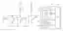
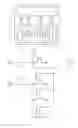
FIG. 1 is an illustration of an optical mouse sensor according to an exemplary embodiment of the present invention.
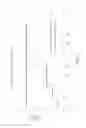
FIG. 2 is a graph illustrating an LED current setting vs. ips for both the present invention and the prior art.
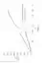
FIG. 3 is a graph illustrating LED power vs. ips for both the present invention and the prior art.
DETAILED DESCRIPTION
The present invention aims to provide a speed-controlled LED setting which will seamlessly step up or down the LED current for an optical mouse sensor.
Refer to FIG. 1, which is an illustration of an optical mouse sensor 100 according to an exemplary embodiment of the present invention. The right hand side of the diagram is a block diagram showing the main functional blocks of the optical mouse sensor 100 and the left hand side of the diagram shows the circuit structure of a constant current LED driver 130 in the optical mouse sensor 100. The optical mouse sensor 100 comprises a pixel and analog front-end circuit 120, which also includes an amplifier and analog-to-digital (ADC) circuit, both of which are not shown. The optical mouse sensor further includes a constant current LED driver 130 and an oscillator 140. A digital circuit (denoted by “DIG”) 150 exchanges signals with the above circuits. The digital circuit 150 informs the pixel and analog front end circuit 120 of the shutter speed of the optical mouse, and receives signals from the pixel and analog front end circuit 120 comprising a number of data bits. The digital circuit 150 defines and decodes the frame rate. The oscillator 140 informs the digital circuit 150 of the clock rate.
The digital circuit 150 can send a control signal to the constant current LED driver 130. In the prior art, the current setting will not vary with speed. Therefore there are available bits on the control signal ctrl<n:0>, which can be used to change the current setting. As shown in the circuit level diagram, the control bits are used to open and close switches within the LED driver 130, so that the current supplied to the LED can be varied. The particular bits selected on the control signal are decoded by the digital circuit 150 according to speed and frame rate threshold.
Please refer to Table 1 below, which shows example figures for varying LED current settings in accordance with speed and frame rate of the optical mouse sensor.
| TABLE 1 | |||||
| Minimum | LED | LED ON | |||
| frame | current | pulse | |||
| Frame | period | setting | width | ||
| Speed | rate, fps | (us) | Ctrl<n:0> | (mA) | (us) |
| <40 ips | <1,000 | 1000 | 0000, | 4 | 88 |
| 0100 | |||||
| 40-100 ips | 1,000-4,000 | 250 | 0000, | 8 | 64 |
| 1000 | |||||
| 101-200 ips | 4,001-7,500 | 133 | 0001, | 12 | 52 |
| 0000 | |||||
| 201-400 ips | 7,501-15,000 | 67 | 0001, | 26 | 41 |
| 1010 | |||||
Refer to FIG. 2, which illustrates the above values graphically for current setting vs. speed. As shown in the graph, the conventional LED will have a constant current setting no matter what the speed is. In the present invention, the current setting is ramped up according to the speed. At lower speeds, there are looser requirements for frame period and speed performance, and decent mouse tracking can still be achieved at a low LED current setting. Please note that the pulse width is extended slightly at the lower current settings (88 us for a current setting of 4 mA). At the higher speeds, i.e. when the frame rate is 15,000 fps or more, the minimum frame period is 67 us, during which the sensor has to complete image acquisition with an image which is sharp enough to enable proper tracking at these higher speeds. The LED current must therefore be increased to the maximum setting.
As detailed in the summary, the advantage of this ramping of LED current according to speed is that significant power saving can be achieved. Please refer to Table 2 below, which illustrates power saving compared to the conventional art at different speed and corresponding current settings.
| LED current | Invention | Conventional | ||
| setting | average LED | average LED | % power | |
| Speed | (mA) | power (mW) | power (mW) | saving |
| <40 ips | 4 | 0.48 | 2.07 | 77% |
| 41-100 ips | 8 | 3.64 | 11.42 | 68% |
| 101-200 ips | 12 | 8.19 | 13.98 | 41% |
| 201-400 ips | 26 | 28.66 | 28.66 | 0% |
Refer to FIG. 3, which illustrates the above values graphically for average LED power vs. speed. As shown in the graph, the conventional LED will have a constant increase whereas the invention will increase in steps until about 250 ips, at which point the slope of average power vs. speed is the same as the conventional LED.
It should be noted that the ramping up in 4 stages is provided here as an illustration of the method of the present invention. In practise, the invention is not restricted to the number of current ramping stages. Further, although the graphs illustrate gradual implementation of the increased current with respect to speed, it is possible to implement an instantaneous step, i.e. where a mouse is initially moved at a speed less than 40 ips and then suddenly increases to over 400 ips. The implementation of this instantaneous change is only restricted by the limitations of the digital algorithm for adjusting the LED current with changes in parameters.
Those skilled in the art will readily observe that numerous modifications and alterations of the device and method may be made while retaining the teachings of the invention. Accordingly, the above disclosure should be construed as limited only by the metes and bounds of the appended claims.
Claims
1: An LED current ramping method for an optical mouse, the method comprising:
determining a speed of the optical mouse;
setting control bits according to the determined speed;
sending the control bits to a digital circuit of the mouse; and
decoding the control bits to selectively open and close switches in a constant current LED driver of the mouse to adjust a constant current according to the speed.
2: The LED current ramping method of claim 1, wherein the current is low at low speeds and ramped up at higher speeds.
3: The LED current ramping method of claim 2, wherein the current is ramped up in four stages.
4: The LED current ramping method of claim 2, wherein the current can be ramped up to a highest level in a single stage.
5: The LED current ramping method of claim 1, wherein the step of decoding the control bits is further according to a frame rate threshold.
Images & Drawings included:
Sources:
- United States Patent and Trademark Office - verify current appl. status at the USPTO↗
Recent applications in this class:
- » 20250110580 2025-04-03
OPTICAL SENSING OF TRANSLATIONAL AND ROTATIONAL SHAFT MOVEMENTS - » 20240036658 2024-02-01
POINTER POSITIONING METHOD AND APPARATUS, AND INSTRUMENT - » 20240019943 2024-01-18
User interface device of display device and method for controlling the same - » 20230359285 2023-11-09
Input device - » 20230124218 2023-04-20
Input device - » 20220155879 2022-05-19
Input device - » 20220035459 2022-02-03
Optical processing apparatus and operating method of watch - » 20210200332 2021-07-01
Determining orientation of a trackball - » 20200356187 2020-11-12
High accuracy tracking system for interactive equipment for simulation or operational employment - » 20200209983 2020-07-02
Pen-shaped folding mouse
Recent applications for this Assignee:
- » 20240003714 2024-01-04
Multi-track optical encoder - » 20220381588 2022-12-01
Multi-track optical encoder - » 20180158436 2018-06-07
Method for syncing mouse report rate and screen refresh rate - » 20180061060 2018-03-01
Edge detection with shutter adaption - » 20180024221 2018-01-25
Scheme capable of calibrating value of sampling precision of optical sensor for tracking - » 20170277278 2017-09-28
Circuit and method for detecting working and resting states for optical mouse - » 20170167898 2017-06-15
Scheme for interrupt-based motion reporting - » 20170133422 2017-05-11
Apparatus and sensor chip component attaching method - » 20170131799 2017-05-11
Non transitory computer readable recording medium for executing image processing method, and image sensing device applying the image processing method - » 20170123511 2017-05-04
System and method for eliminating spurious motion of mouse