Cantilever for a utility vehicle
US20180195252A1
2018-07-12
15/571,791
2016-05-03
✅ Patent granted
US 10,208,450 B2
2019-02-19
WO; PCT/AT2016/000052; 20160503
WO; WO2016/176699; 20161110
Gerald McClain
Young & Thompson
2036-05-03
Abstract:
Disclosed is a cantilever, including: a spar connected rotatably about a rear fixed axis to a fastening device for a vehicle; a tool lever connected rotatably about a front fixed axis to the spar; a deflecting triangle connected rotatably about a central fixed axis to the spar; a rear strut connected rotatably about a first strut pivot axis to the fastening device and rotatably about a second strut pivot axis to the deflecting triangle; a front strut connected rotatably about a third strut pivot axis to the deflecting triangle and rotatably about a fourth strut pivot axis to the tool lever. The rear and the central fixed axis span a first plane, the rear strut intersects the first plane, the central and the front fixed axis span a second plane, and the front strut intersects the second plane.
Assignee:
- Ronald Hauer 1 🇦🇹 Statzendorf, Austria
Applicant:
Interested in similar patents?
Get notified when new applications in this technology area are published.
Classification:
E02F3/3417 » CPC further
Dredgers; Soil-shifting machines mechanically-driven with digging tools mounted on a dipper- or bucket-arm, i.e. there is either one arm or a pair of arms , e.g. dippers, buckets with bucket-arms, i.e. a pair of arms, e.g. manufacturing processes, form, geometry, material of bucket-arms directly pivoted on the frames of tractors or self-propelled machines Buckets emptying by tilting
E02F3/3677 » CPC further
Dredgers; Soil-shifting machines mechanically-driven with digging tools mounted on a dipper- or bucket-arm, i.e. there is either one arm or a pair of arms , e.g. dippers, buckets; Component parts; Devices to connect tools to arms, booms or the like allowing movement, e.g. rotation or translation, of the tool around or along another axis as the movement implied by the boom or arms, e.g. for tilting buckets
E02F3/3695 » CPC further
Dredgers; Soil-shifting machines mechanically-driven with digging tools mounted on a dipper- or bucket-arm, i.e. there is either one arm or a pair of arms , e.g. dippers, buckets; Component parts Arrangements for connecting dipper-arms to loaders or graders
E02F9/2271 » CPC further
Component parts of dredgers or soil-shifting machines, not restricted to one of the kinds covered by groups - ; Drives; Control devices; Hydraulic or pneumatic drives; Arrangements or adaptations of elements for hydraulic drives Actuators and supports therefor and protection therefor
E02F3/34 IPC
Dredgers; Soil-shifting machines mechanically-driven with digging tools mounted on a dipper- or bucket-arm, i.e. there is either one arm or a pair of arms , e.g. dippers, buckets with bucket-arms, i.e. a pair of arms, e.g. manufacturing processes, form, geometry, material of bucket-arms directly pivoted on the frames of tractors or self-propelled machines
E02F3/28 IPC
Dredgers; Soil-shifting machines mechanically-driven with digging tools mounted on a dipper- or bucket-arm, i.e. there is either one arm or a pair of arms , e.g. dippers, buckets
E02F3/36 IPC
Dredgers; Soil-shifting machines mechanically-driven with digging tools mounted on a dipper- or bucket-arm, i.e. there is either one arm or a pair of arms , e.g. dippers, buckets Component parts
E02F9/22 IPC
Component parts of dredgers or soil-shifting machines, not restricted to one of the kinds covered by groups - ; Drives; Control devices Hydraulic or pneumatic drives
E02F3/283 » CPC further
Dredgers; Soil-shifting machines mechanically-driven with digging tools mounted on a dipper- or bucket-arm, i.e. there is either one arm or a pair of arms , e.g. dippers, buckets with a single arm pivoted directly on the chassis
E02F3/38 » CPC main
Dredgers; Soil-shifting machines mechanically-driven with digging tools mounted on a dipper- or bucket-arm, i.e. there is either one arm or a pair of arms , e.g. dippers, buckets; Component parts Cantilever beams, i.e. booms;, e.g. manufacturing processes, forms, geometry or materials used for booms ; Dipper-arms, e.g. manufacturing processes, forms, geometry or materials used for dipper-arms ; Bucket-arms
E02F3/3411 » CPC further
Dredgers; Soil-shifting machines mechanically-driven with digging tools mounted on a dipper- or bucket-arm, i.e. there is either one arm or a pair of arms , e.g. dippers, buckets with bucket-arms, i.e. a pair of arms, e.g. manufacturing processes, form, geometry, material of bucket-arms directly pivoted on the frames of tractors or self-propelled machines and comprising an additional linkage mechanism of the Z-type
E02F3/627 » CPC further
Dredgers; Soil-shifting machines mechanically-driven Devices to connect beams or arms to tractors or similar self-propelled machines, e.g. drives therefor
E02F3/43 IPC
Dredgers; Soil-shifting machines mechanically-driven with digging tools mounted on a dipper- or bucket-arm, i.e. there is either one arm or a pair of arms , e.g. dippers, buckets; Component parts; Drives for dippers, buckets, dipper-arms or bucket-arms Control of dipper or bucket position; Control of sequence of drive operations
Description
The invention relates to a cantilever, in particular for a utility vehicle,
-
- Whereby a spar is connected so as to rotate around a rear fixed axis with a fastening device for a vehicle,
- Whereby a tool lever is connected so as to rotate around a front fixed axis with the spar,
- Whereby a deflecting triangle is connected so as to rotate around a central fixed axis with the spar,
- Whereby a rear strut is connected so as to rotate around a first strut pivot axis with the fastening device and so as to rotate around a second strut pivot axis with the deflecting triangle,
- And whereby a front strut is connected so as to rotate around a third strut pivot axis with the deflecting triangle and so as to rotate around a fourth strut pivot axis with the tool lever.
Such cantilevers that are usually embodied as parallel guides are known from, for example, EP 1 903 147 A. In general, two such cantilevers are mounted on a vehicle beside one another and connected to one another, and they move a tool that is fastened to the cantilevers. In addition to a control that is as accurate as possible, in this case there are additional aims to improve such cantilevers. On the one hand, the field of view of an operator is to be limited as little as possible; on the other hand, the cantilever is to be able to be operated as safely as possible. Both can be achieved in that as many elements of the cantilever as possible are concealed under a lining. Thus, fouling of the movable parts of the cantilever leading to wear can be reduced. In addition, many movable parts, which otherwise represent a potential risk of injury, are no longer easily accessible. However, in the case of a conventional arrangement of the elements of a parallel guide, the lining occupies a large part of the field of view of an operator, which greatly limits comfort during operation, on the one hand, and creates a new safety risk, on the other hand, since the operator can no longer survey his environs.
EP 1 903 147 A supplies a proposed solution to make the cantilever more slender and thus to give the operator a better field of view. In this case, a strut of the cantilever is bent in such a way that the central area of the strut is offset further into the spar for the most part. This has the drawback, however, that the strut, which has buckling points or a curvature created by this shape, loses stability. This has to be offset by making the strut more massive, which both makes production more expensive and produces a higher weight.
The object of the invention is therefore to overcome the above-described drawbacks and to make available a compact—and in this case sturdy and economical—option for cantilevers of the above-mentioned type.
This object is achieved according to the invention by a cantilever of the above-mentioned type, which is characterized in that
-
- The rear and the central fixed axes span a first plane and in that the rear strut intersects the first plane,
- In that the central and the front fixed axes span a second plane and in that the front strut intersects the second plane.
Because of this non-parallel, but “crosswise,” arrangement, much more space can be saved, whereby the rear strut winds up bent to a much lesser extent. In this case, the spar acts simultaneously as a lining and a carrier for the fixed axes. Thus, only the struts that pivot around movable axes are necessary.
This saves space and simultaneously eliminates the necessity for a parallel arrangement. In a preferred embodiment, the struts are therefore arranged essentially inside the spar.
In a preferred further development of the invention, the front strut has a tool drive, by which the length of the strut can be changed in order to move the tool lever. Of course, embodiments without a tool drive are also conceivable. In this case, the tool, as known from parallel guides, is moved. In another preferred embodiment of the invention, a tool guide that can be connected with a tool is arranged for the movement on the tool lever.
In order to configure the tool lever and the associated tool guide in an easily accessible manner, the tool lever—in another preferred embodiment—is arranged essentially half outside and half inside the spar.
In the state of the art, in the case of cantilevers that have a sharp bend, the deflecting triangle is arranged oriented in the area of the sharp bend and with the (central) fixed axis on the outside of the sharp bend. In an especially preferred embodiment of the invention, the crossing is created in such a way that the deflecting triangle is arranged inversely. Consequently, in an especially preferred embodiment of the invention, the spar has a sharp bend, the central fixed axis of the deflecting triangle is arranged in the area of the inside of the sharp bend, and the second and third strut pivot axes are arranged at some distance therefrom.
Additional preferred embodiments of the invention are the subject matter of the other subclaims.
Below, a preferred embodiment of the invention is described in more detail based on the drawings. Here:
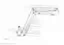
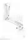
FIG. 1 shows a section through a cantilever 1 with a tool 2, and
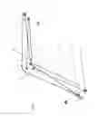
FIG. 2 shows the cantilever with connecting lines and longitudinal axes depicting the invention in schematized form.
The cantilever 1 shown in FIG. 1 with a tool 2 has a spar 3, which is used both as a carrier for various elements of the cantilever and as a lining of the cantilever. The spar 3 is connected so as to rotate around a rear fixed axis 4 with a fastening device 5. With the fastening device 5, the cantilever 1 can be fastened to a vehicle. Of course, embodiments are also conceivable in which the fastening device 5 is a more integral component of the utility vehicle. At the other end of the spar 3, a tool lever 6 is connected so as to rotate around a front fixed axis 7 with the spar 3. In a central area of the spar 3, a deflecting triangle 8 is arranged. The deflecting triangle 8 is connected so as to rotate around a central fixed axis 9 with the spar 3. A rear strut 11 is connected so as to rotate around a first strut pivot axis 12 with the fastening device 5 and so as to rotate around a second strut pivot axis 13 with the deflecting triangle 8. A front strut 14 is connected so as to rotate around a third strut pivot axis 15 with the deflecting triangle 8 and so as to rotate around a fourth strut pivot axis 16 with the tool lever 6. In the depicted embodiment, the front strut 14 has a tool drive 17, via which the length of the front strut 14 can be changed. Thus, the position of the tool 2 can be changed via the tool lever 6. In the depicted embodiment, in this connection, a tool guide 18 is connected so as to rotate around a guide pivot axis 19 with the tool lever 6. In order to move the spar 3 relative to the vehicle or the fastening device 5, a lifting drive 21 is provided.
It is clear that the rear fixed axis 4 in the depicted orientation of the cantilever 1 lies above the first strut pivot axis 12, and the central fixed axis 9 lies below the second strut pivot axis 13. This is accomplished in that the deflecting triangle 8, unlike in the state of the art, is arranged inversely in the spar 3. The deflecting triangle 8 is thus located specifically in the area of a sharp bend 22 of the spar 3, as is common in the state of the art. However, the central fixed axis of the deflecting triangle 8 is arranged in the area of an inner side of the sharp bend 22.
The basic crosswise arrangement of the struts according to the invention is illustrated in more detail in FIG. 2 with reference to the fixed axes. Longitudinal axes of the struts 11, 14, depicted symbolically in each case by dotted lines 23, 24, are shown by the rear and front struts 11, 14. In addition, dashed-dotted connecting lines 25, 26 are indicated between the fixed axes 4, 7, 9. In this case, a rear dashed-dotted connecting line 25 symbolically shows a first plane that is spanned by the rear fixed axis 4 and the central fixed axis 9. A front dashed-dotted line 26 symbolically shows a second plane that is spanned by the central fixed axis 9 and the front fixed axis 7.
It is clear that the rear strut 11 that is depicted by the rear dotted line 23 intersects the first plane and that the front strut 14, which is symbolically depicted by the front dotted line 24, intersects the second plane.
Claims
1. Cantilever (1), in particular for a utility vehicle,
Whereby a spar (3) is connected so as to rotate around a rear fixed axis (4) with a fastening device (5) for a vehicle,
Whereby a tool lever (6) is connected so as to rotate around a front fixed axis (7) with the spar (3),
Whereby a deflecting triangle (8) is connected so as to rotate around a central fixed axis (9) with the spar (3),
Whereby a rear strut (11) is connected so as to rotate around a first strut pivot axis (12) with the fastening device (5) and so as to rotate around a second strut pivot axis (13) with the deflecting triangle (8),
And whereby a front strut (14) is connected so as to rotate around a third strut pivot axis (15) with the deflecting triangle (8) and so as to rotate around a fourth strut pivot axis (16) with the tool lever (6),
wherein
The rear and the central fixed axes (4, 9) span a first plane and wherein the rear strut (11) intersects the first plane,
wherein the central and the front fixed axes (9, 7) span a second plane and wherein the front strut (14) intersects the second plane.
2. Cantilever (1) according to claim 1, wherein the front strut (14) has a tool drive (17), by which the length of the strut (14) can be changed.
3. Cantilever (1) according to claim 1, wherein the struts (11, 14) are arranged essentially inside the spar (3).
4. Cantilever (1) according to claim 1, wherein the deflecting triangle (8) is arranged inside the spar (3).
5. Cantilever (1) according to claim 1, wherein the spar (3) has a sharp bend (22), wherein the central fixed axis (9) of the deflecting triangle (8) is arranged in the area of the inside of the sharp bend (22), and wherein the second and third strut pivot axes (13, 15) are arranged at some distance therefrom.
6. Cantilever (1) according to claim 1, wherein the tool lever (6) is arranged essentially half outside and half inside the spar (3).
7. Cantilever (1) according to claim 1, wherein a tool guide (18) that can be connected with a tool is arranged on the tool lever (6).
8. Vehicle, in particular utility vehicle, wherein the vehicle has at least one cantilever (1) according to claim 1.
9. Vehicle according to claim 8, wherein the vehicle has two cantilevers.
10. The vehicle of claim 9, wherein the two cantilevers are connected to one another.
11. Cantilever (1) according to claim 2, wherein the struts (11, 14) are arranged essentially inside the spar (3).
12. Cantilever (1) according to claim 2, wherein the deflecting triangle (8) is arranged inside the spar (3).
13. Cantilever (1) according to claim 3, wherein the deflecting triangle (8) is arranged inside the spar (3).
14. Cantilever (1) according to claim 2, wherein the spar (3) has a sharp bend (22), wherein the central fixed axis (9) of the deflecting triangle (8) is arranged in the area of the inside of the sharp bend (22), and wherein the second and third strut pivot axes (13, 15) are arranged at some distance therefrom.
15. Cantilever (1) according to claim 3, wherein the spar (3) has a sharp bend (22), wherein the central fixed axis (9) of the deflecting triangle (8) is arranged in the area of the inside of the sharp bend (22), and wherein the second and third strut pivot axes (13, 15) are arranged at some distance therefrom.
16. Cantilever (1) according to claim 4, wherein the spar (3) has a sharp bend (22), wherein the central fixed axis (9) of the deflecting triangle (8) is arranged in the area of the inside of the sharp bend (22), and wherein the second and third strut pivot axes (13, 15) are arranged at some distance therefrom.
17. Cantilever (1) according to claim 2, wherein the tool lever (6) is arranged essentially half outside and half inside the spar (3).
18. Cantilever (1) according to claim 3, wherein the tool lever (6) is arranged essentially half outside and half inside the spar (3).
19. Cantilever (1) according to claim 4, wherein the tool lever (6) is arranged essentially half outside and half inside the spar (3).
20. Cantilever (1) according to claim 5, wherein the tool lever (6) is arranged essentially half outside and half inside the spar (3).
Images & Drawings included:
Sources:
- United States Patent and Trademark Office - verify current appl. status at the USPTO↗
Recent applications in this class:
- » 20250207349 2025-06-26
CABLESS LOADER LIFT ARM - » 20250052031 2025-02-13
WELDED STRUCTURE AND WORK VEHICLE - » 20240360644 2024-10-31
BOOM ASSEMBLY - » 20240344293 2024-10-17
LOADER LIFT ARM - » 20240309602 2024-09-19
Method of Manufacturing a Working Arm for a Working Machine - » 20240150993 2024-05-09
WORK MACHINE ARM, WORK IMPLEMENT, AND WORK MACHINE - » 20240060266 2024-02-22
RANGE-EXTENDED NUMERICAL CONTROLLED LINK MECHANISM ELECTRIC LOADER - » 20230081760 2023-03-16
WORK MACHINE - » 20220372726 2022-11-24
Self-leveling lift arm assembly for power machines - » 20210381193 2021-12-09
Work machine