MOBILE POWER SOURCE
US20180198302A1
2018-07-12
15/757,527
2016-07-19
Abstract:
A mobile power source includes an upper cover, a charging battery, a circuit board, a group of charging input metal contacts and a lower cover. The upper cover and lower cover match to form a mobile power source case, and the charging battery and group of charging input metal contacts are respectively electrically connected to the circuit board. The charging battery and circuit board are accommodated in the mobile power source case, and the group of charging input metal contacts are exposed outside of the mobile power source case.
Inventors:
- Weige YU 1 🇨🇳 SHENZHEN, GUANGDONG, China
- Xiaoyi YE 1 🇨🇳 SHENZHEN, GUANGDONG, China
- Fengchi XIAO 1 🇨🇳 SHENZHEN, GUANGDONG, China
- Xiaowei ZHENG 1 🇨🇳 SHENZHEN, GUANGDONG, China
- Baoming TANG 1 🇨🇳 SHENZHEN, GUANGDONG, China
- Guansheng YAN 1 🇨🇳 SHENZHEN, GUANGDONG, China
- Bingsong YUAN 1 🇨🇳 SHENZHEN, GUANGDONG, China
- Qiongying ZHUANG 1 🇨🇳 SHENZHEN, GUANGDONG, China
Assignee:
- SHENZHEN LAIDIAN TECHNOLOGY CO., LTD. 3 🇨🇳 SHENZHEN, GUANGDONG, China
Interested in similar patents?
Get notified when new applications in this technology area are published.
Classification:
H01M2220/30 » CPC further
Batteries for particular applications Batteries in portable systems, e.g. mobile phone, laptop
H02J7/0045 » CPC further
Circuit arrangements for charging or depolarising batteries or for supplying loads from batteries characterised by the mechanical construction concerning the insertion or the connection of the batteries
H02J7/00 IPC
Circuit arrangements for charging or depolarising batteries or for supplying loads from batteries
H01M10/46 » CPC further
Secondary cells; Manufacture thereof; Methods or arrangements for servicing or maintenance of secondary cells or secondary half-cells Accumulators structurally combined with charging apparatus
Description
CROSS-REFERENCE TO RELATED APPLICATIONS
This is a national stage application filed under 35 U.S.C. 371 of pending international application PCT/CN2016/090419, filed Jul. 19, 2016, which claims priority to Chinese patent application CN 201520691258.0, filed Sep. 7, 2015, the entirety of which applications are incorporated by reference herein.
TECHNICAL FIELD
The present disclosure pertains to the field of power source, and particularly relates to a mobile power source.
BACKGROUND
The current mobile power sources on the market are basically charged via a Micro USB interface, and in such a charging mode, for situations or devices requiring heavy use of a mobile power source, since it is required to manually insert charging lines into the Micro USB interface of the mobile power source one by one, the efficiency is very low; however, if the operation is made by a machine, the machine is required to have a very high accuracy.
SUMMARY
Embodiments of the present disclosure provides a mobile power source, comprising an upper cover, a charging battery, a circuit board, a group of charging input metal contacts and a lower cover. The upper cover and lower cover match to form a mobile power source case, the charging battery and the group of charging input metal contacts are respectively electrically connected to the circuit board, the charging battery and the circuit board are accommodated in the mobile power source case, and the group of charging input metal contacts are exposed outside of the mobile power source case.
In an example, the upper cover and the lower cover match to form the mobile power source case by means of a buckle or ultrasonic welding.
In an example, the group of charging input metal contacts are electrically connected to a charging input of the circuit board.
In an example, the charging battery is electrically connected to a charging output of the circuit board.
In an example, the group of charging input metal contacts are exposed outside of a side where the upper cover and the lower cover match.
In an example, the power mobile source further comprises another group of charging input metal contacts or a plurality of groups of charging input metal contacts, wherein each group of charging input metal contacts is exposed outside of a different side of the mobile power source case.
In an example, the charging input metal contacts are of a round or square shape.
In an example, each group of charging input metal contacts at least include two charging input metal contacts, wherein one charging input metal contact is electrically connected to a positive electrode of the charging input of the circuit board, and the other charging input metal contact is electrically connected to a negative electrode of the charging input of the circuit board.
In an example, the mobile power source further comprises a MICRO USB interface electrically connected to the charging input of the circuit board, and/or a MINI USB interface electrically connected to the charging input of the circuit board, wherein both the MICRO USB interface and the MINI USB interface are exposed outside of the mobile power source case.
In an example, the mobile power source further comprises a power source output USB interface electrically connected to the circuit board, wherein the power source output USB interface is exposed outside of the mobile power source case.
In the disclosure, since the charging input metal contacts serve as charging inputs, the charging is available if the charging input metal contacts of the mobile power source are aligned with a charging base with a spring contact or spring member; since the charging input metal contacts have a certain surface area, even if the charging is made by aligning the mobile power source with the charging base through a machine, the machine is not required to have a high accuracy, and it is only required to ensure that the spring contact or spring member on the charging base contacts with the charging input metal contacts. Further, since the operation can be made by a machine, it has a high operating efficiency for situations or devices requiring heavy use of a mobile power source.
BRIEF DESCRIPTION OF THE DRAWINGS
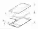
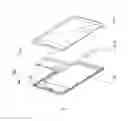
FIG. 1 is an exploded view of a mobile power source provided by an embodiment of the disclosure.
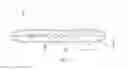
FIG. 2 is a schematic view of the mobile power source provided by the embodiment of the disclosure.
DETAILED DESCRIPTION
Embodiments of the disclosure provide a mobile power source, which aims to solve the following problem: the mobile power source that is charged via the Micro USB interface has a very low manual operating efficiency, but if the operation is made by a machine, the machine is required to have a very high accuracy.
In order to make the objective, technical solution and beneficial effects of the disclosure clearer, the disclosure will be further described in detail below in combination with the accompanying drawings and the embodiments. It should be appreciated that, the embodiments described herein are merely used for explaining the disclosure but not for limiting the disclosure.
In order to describe the technical solution of the disclosure, the following embodiments are provided.
Please refer to FIG. 1 and FIG. 2, the mobile power source provided by an embodiment of the disclosure comprises an upper cover 1, a charging battery 2, a circuit board 3, a group of charging input metal contacts 4 and a lower cover 5. The upper cover 1 and lower cover 5 match to form a mobile power source case, the charging battery 2 and the group of charging input metal contacts 4 are respectively electrically connected to the circuit board 3, the charging battery 2 and the circuit board 3 are accommodated in the mobile power source case, and the group of charging input metal contacts 4 are exposed outside of the mobile power source case.
The circuit board 3 in the embodiment of the disclosure can achieve the functions of charging and discharging management and protection of the charging battery 2.
In the embodiment of the disclosure, the upper cover 1 and the lower cover 5 match to form the mobile power source case, specifically by means of a buckle or ultrasonic welding. The group of charging input metal contacts 4 specifically are electrically connected to a charging input of the circuit board 3, and the charging battery 2 is electrically connected to a charging output of the circuit board 3. The group of charging input metal contacts 4 specifically are exposed outside of a side where the upper cover 1 and the lower cover 5 match. Of course, the power mobile source may also comprise two groups of charging input metal contacts or a plurality of groups of charging input metal contacts, wherein each group of charging input metal contacts are exposed outside of a different side of the mobile power source case, such that the charging can be successful even if the orientation of the mobile power source is wrongly placed during the charging. Each group of charging input metal contacts at least include two charging input metal contacts, wherein one charging input metal contact is electrically connected to a positive electrode of the charging input of the circuit board 3, and the other charging input metal contact is electrically connected to a negative electrode of the charging input of the circuit board 3. The charging input metal contacts may be of a round or square shape or others.
The mobile power source provided by the embodiment of the disclosure may further comprise a MICRO USB interface electrically connected to the charging input of the circuit board 3, and/or a MINI USB interface 6 electrically connected to the charging input of the circuit board 3, wherein both the MICRO USB interface and the MINI USB interface 6 are exposed outside of the mobile power source case.
The mobile power source provided by the embodiment of the disclosure may further comprise a power source output USB interface 7 electrically connected to the circuit board 3, wherein the power source output USB interface is exposed outside of the mobile power source case, and can directly charge a mobile product by connecting charging lines to the power source output USB interface.
In the disclosure, since the charging input metal contacts serve as charging inputs, the charging is available if the charging input metal contacts of the mobile power source are aligned with the charging base with a spring contact or spring member; since the charging input metal contacts have a certain surface area, even if the charging is made by aligning the mobile power source with the charging base through a machine, the machine is not required to have a high accuracy, and it is only required to ensure that the spring contact or spring member on the charging base contacts with the charging input metal contacts. Further, since the operation can be made by a machine, it has a high operating efficiency for situations or devices requiring heavy use of a mobile power source.
The above only describes advantageous embodiments of the disclosure and is not used for limiting the disclosure, and any modification, equivalent replacement and improvement made within the spirit and rule of the disclosure should be embraced in the scope of protection of the disclosure.
Claims
1. A mobile power source comprising an upper cover, a charging battery, a circuit board, a group of charging input metal contacts and a lower cover, wherein the upper cover and lower cover match to form a mobile power source case, the charging battery and the group of charging input metal contacts are respectively electrically connected to the circuit board, the charging battery and the circuit board are accommodated in the mobile power source case, and the group of charging input metal contacts are exposed outside of the mobile power source case, wherein the power mobile source further comprises another group of charging input metal contacts or a plurality of groups of charging input metal contacts, wherein each group of charging input metal contacts is exposed outside of a different side of the mobile power source case.
2. The mobile power source according to claim 1, wherein the upper cover and the lower cover match to form the mobile power source case by means of a buckle or ultrasonic welding.
3. The mobile power source according to claim 1, wherein the group of charging input metal contacts are electrically connected to a charging input of the circuit board.
4. The mobile power source according to claim 1, wherein the charging battery is electrically connected to a charging output of the circuit board.
5. The mobile power source according to claim 1, wherein the group of charging input metal contacts are exposed outside of a side where the upper cover and the lower cover match.
6. (canceled)
7. The mobile power source according to claim 1, wherein the charging input metal contacts are of a round or square shape.
8. The mobile power source according to claim 1, wherein each group of charging input metal contacts at least includes two charging input metal contacts, wherein one charging input metal contact is electrically connected to a positive electrode of the charging input of the circuit board, and the other charging input metal contact is electrically connected to a negative electrode of the charging input of the circuit board.
9. The mobile power source according to claim 1, wherein the mobile power source further comprises a MICRO USB interface electrically connected to the charging input of the circuit board, and/or a MINI USB interface electrically connected to the charging input of the circuit board, wherein both the MICRO USB interface and the MINI USB interface are exposed outside of the mobile power source case.
10. The mobile power source according to claim 1, wherein the mobile power source further comprises a power source output USB interface electrically connected to the circuit board, wherein the power source output USB interface is exposed outside of the mobile power source case.
Images & Drawings included:
Sources:
- United States Patent and Trademark Office - verify current appl. status at the USPTO↗
Similar patent applications:
- » 20210351602
MOBILE POWER SOURCE SHARING DEVICE AND MOBILE POWER SOURCE THEREOF - » 20230057294
MOBILE POWER SOURCE FOR A MOBILE ROBOT - » 20190067965
Separable Mobile Power Source Bracket - » 20160098770
Mobile power source and method of use - » 20190013686
MOBILE POWER SOURCE - » 20190058333
Mobile power source - » 20100072827
Mobile power source for use with a hand-held machine and method of operating - » 20150188341
MOBILE POWER SOURCE WITH KEYBOARD - » 20070047181
Mobile power source cable connection system and method - » 20160006287
MOBILE POWER SOURCE WITH A SINGLE INTERFACE, A BLUETOOTH KEYBOARD AND A PROTECTIVE SLEEVE
Recent applications in this class:
- » 20210104900 2021-04-08
POWER BANK - » 20200274382 2020-08-27
Cordless appliance, such as a surface cleaning apparatus, and a charging unit therefor - » 20200274381 2020-08-27
Cordless appliance, such as a surface cleaning apparatus, and a charging unit therefor - » 20200185943 2020-06-11
Supplementary charging system and method for auxiliary battery of eco-friendly vehicle - » 20200161885 2020-05-21
Motorized personal transport controller and charging port - » 20200127482 2020-04-23
Dynamic adjustment of charging voltage supplied from a first device to a second device - » 20200091750 2020-03-19
Electric power supply system - » 20200091749 2020-03-19
PORTABLE POWER SOURCE - » 20200076216 2020-03-05
Device for charging electronic devices and boosting signals - » 20200067334 2020-02-27
Wireless electric power sharing between vehicles
Recent applications for this Assignee:
- » 20180025573 2018-01-25
Leasing terminal of mobile power supply - » 20180019604 2018-01-18
Retractable charging apparatus