METHOD FOR RECEIVING A SIGNAL IN WIRELESS COMMUNICATION SYSTEM AND A DEVICE THEREFOR
US20180199208A1
2018-07-12
15/746,385
2016-06-08
Abstract:
The present invention relates to a wireless communication system. More specifically, the present invention relates to a method and a device for receiving a signal in wireless communication system, the method comprising: configuring a plurality of cells; receiving information for configuring a radio bearer; and if the information includes an indication indicating at least one cell among the plurality of cells on which a data of the configured radio bearer is to be transmitted, transmitting a data of the radio bearer on the at least one cell indicated by the indication.
Assignee:
- LG ELECTRONICS INC. 41,625 🇰🇷 Seoul, South Korea
Interested in similar patents?
Get notified when new applications in this technology area are published.
Classification:
H04W28/0268 » CPC further
Network traffic or resource management; Traffic management, e.g. flow control or congestion control using specific QoS parameters for wireless networks, e.g. QoS class identifier [QCI] or guaranteed bit rate [GBR]
H04W72/042 » CPC further
Local resource management, e.g. wireless traffic scheduling or selection or allocation of wireless resources; Wireless resource allocation involving control information exchange between nodes in downlink direction of a wireless link, i.e. towards terminal
H04W16/24 » CPC main
Network planning, e.g. coverage or traffic planning tools; Network deployment, e.g. resource partitioning or cells structures Cell structures
H04W72/04 IPC
Local resource management, e.g. wireless traffic scheduling or selection or allocation of wireless resources Wireless resource allocation
H04W28/02 IPC
Network traffic or resource management Traffic management, e.g. flow control or congestion control
Description
TECHNICAL FIELD
The present invention relates to a wireless communication system and, more particularly, to a method for receiving a signal in wireless communication system and a device therefor.
BACKGROUND ART
As an example of a mobile communication system to which the present invention is applicable, a 3rd Generation Partnership Project Long Term Evolution (hereinafter, referred to as LTE) communication system is described in brief.
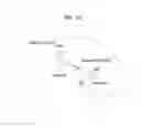
FIG. 1 is a view schematically illustrating a network structure of an E-UMTS as an exemplary radio communication system. An Evolved Universal Mobile Telecommunications System (E-UMTS) is an advanced version of a conventional Universal Mobile Telecommunications System (UMTS) and basic standardization thereof is currently underway in the 3GPP. E-UMTS may be generally referred to as a Long Term Evolution (LTE) system. For details of the technical specifications of the UMTS and E-UMTS, reference can be made to Release 7 and Release 8 of “3rd Generation Partnership Project; Technical Specification Group Radio Access Network”.
Referring to FIG. 1, the E-UMTS includes a User Equipment (UE), eNode Bs (eNBs), and an Access Gateway (AG) which is located at an end of the network (E-UTRAN) and connected to an external network. The eNBs may simultaneously transmit multiple data streams for a broadcast service, a multicast service, and/or a unicast service.
One or more cells may exist per eNB. The cell is set to operate in one of bandwidths such as 1.25, 2.5, 5, 10, 15, and 20 MHz and provides a downlink (DL) or uplink (UL) transmission service to a plurality of UEs in the bandwidth. Different cells may be set to provide different bandwidths. The eNB controls data transmission or reception to and from a plurality of UEs. The eNB transmits DL scheduling information of DL data to a corresponding UE so as to inform the UE of a time/frequency domain in which the DL data is supposed to be transmitted, coding, a data size, and hybrid automatic repeat and request (HARQ)-related information. In addition, the eNB transmits UL scheduling information of UL data to a corresponding UE so as to inform the UE of a time/frequency domain which may be used by the UE, coding, a data size, and HARQ-related information. An interface for transmitting user traffic or control traffic may be used between eNBs. A core network (CN) may include the AG and a network node or the like for user registration of UEs. The AG manages the mobility of a UE on a tracking area (TA) basis. One TA includes a plurality of cells.
Although wireless communication technology has been developed to LTE based on wideband code division multiple access (WCDMA), the demands and expectations of users and service providers are on the rise. In addition, considering other radio access technologies under development, new technological evolution is required to secure high competitiveness in the future. Decrease in cost per bit, increase in service availability, flexible use of frequency bands, a simplified structure, an open interface, appropriate power consumption of UEs, and the like are required.
DISCLOSURE
Technical Problem
An object of the present invention devised to solve the problem lies in a method and device for receiving a signal in wireless communication system.
The technical problems solved by the present invention are not limited to the above technical problems and those skilled in the art may understand other technical problems from the following description.
Technical Solution
The object of the present invention can be achieved by providing a method for User Equipment (UE) operating in a wireless communication system as set forth in the appended claims.
In another aspect of the present invention, provided herein is a communication apparatus as set forth in the appended claims.
It is to be understood that both the foregoing general description and the following detailed description of the present invention are exemplary and explanatory and are intended to provide further explanation of the invention as claimed.
Advantageous Effects
According to the present invention, the invention is that the UE transmits data of a bearer on a cell which is mapped to the bearer if the UE receives an indication which indicates the mapping between the bearer and the cell. If the UE does not receive the indication, the UE transmits data of the bearer on any cell.
It will be appreciated by persons skilled in the art that the effects achieved by the present invention are not limited to what has been particularly described hereinabove and other advantages of the present invention will be more clearly understood from the following detailed description taken in conjunction with the accompanying drawings.
DESCRIPTION OF DRAWINGS
The accompanying drawings, which are included to provide a further understanding of the invention and are incorporated in and constitute a part of this application, illustrate embodiment(s) of the invention and together with the description serve to explain the principle of the invention.
FIG. 1 is a diagram showing a network structure of an Evolved Universal Mobile Telecommunications System (E-UMTS) as an example of a wireless communication system;
FIG. 2A is a block diagram illustrating network structure of an evolved universal mobile telecommunication system (E-UMTS), and FIG. 2B is a block diagram depicting architecture of a typical E-UTRAN and a typical EPC;
FIG. 3 is a diagram showing a control plane and a user plane of a radio interface protocol between a UE and an E-UTRAN based on a 3rd generation partnership project (3GPP) radio access network standard;
FIG. 4 is a view showing an example of a physical channel structure used in an E-UMTS system;
FIG. 5 is a block diagram of a communication apparatus according to an embodiment of the present invention;
FIG. 6 illustrates an example of CCs and carrier aggregation in the LTE-A system, which are used in embodiments of the present disclosure;
FIG. 7A is a diagram for MAC structure overview in a UE side, and FIG. 7B is a diagram for MAC PDU consisting of MAC header, MAC control elements, MAC SDUs and padding;
FIG. 8 is a diagram for exemplary Licensed-Assisted Access (LAA) scenarios;
FIG. 9 is conceptual diagrams for diverse data applications for carrier aggregation;
FIGS. 10 to 11 are conceptual diagrams for receiving a signal for diverse data applications for carrier aggregation according to embodiments of the present invention; and
FIG. 12 is an example for receiving a signal for diverse data applications for carrier aggregation according to embodiments of the present invention
BEST MODE
Universal mobile telecommunications system (UMTS) is a 3rd Generation (3G) asynchronous mobile communication system operating in wideband code division multiple access (WCDMA) based on European systems, global system for mobile communications (GSM) and general packet radio services (GPRS). The long-term evolution (LTE) of UMTS is under discussion by the 3rd generation partnership project (3GPP) that standardized UMTS.
The 3GPP LTE is a technology for enabling high-speed packet communications. Many schemes have been proposed for the LTE objective including those that aim to reduce user and provider costs, improve service quality, and expand and improve coverage and system capacity. The 3G LTE requires reduced cost per bit, increased service availability, flexible use of a frequency band, a simple structure, an open interface, and adequate power consumption of a terminal as an upper-level requirement.
Hereinafter, structures, operations, and other features of the present invention will be readily understood from the embodiments of the present invention, examples of which are illustrated in the accompanying drawings. Embodiments described later are examples in which technical features of the present invention are applied to a 3GPP system.
Although the embodiments of the present invention are described using a long term evolution (LTE) system and a LTE-advanced (LTE-A) system in the present specification, they are purely exemplary. Therefore, the embodiments of the present invention are applicable to any other communication system corresponding to the above definition. In addition, although the embodiments of the present invention are described based on a frequency division duplex (FDD) scheme in the present specification, the embodiments of the present invention may be easily modified and applied to a half-duplex FDD (H-FDD) scheme or a time division duplex (TDD) scheme.
FIG. 2A is a block diagram illustrating network structure of an evolved universal mobile telecommunication system (E-UMTS). The E-UMTS may be also referred to as an LTE system. The communication network is widely deployed to provide a variety of communication services such as voice (VoIP) through IMS and packet data.
As illustrated in FIG. 2A, the E-UMTS network includes an evolved UMTS terrestrial radio access network (E-UTRAN), an Evolved Packet Core (EPC) and one or more user equipment. The E-UTRAN may include one or more evolved NodeB (eNodeB) 20, and a plurality of user equipment (UE) 10 may be located in one cell. One or more E-UTRAN mobility management entity (MME)/system architecture evolution (SAE) gateways 30 may be positioned at the end of the network and connected to an external network.
As used herein, “downlink” refers to communication from eNodeB 20 to UE 10, and “uplink” refers to communication from the UE to an eNodeB. UE 10 refers to communication equipment carried by a user and may be also referred to as a mobile station (MS), a user terminal (UT), a subscriber station (SS) or a wireless device.
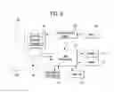
FIG. 2B is a block diagram depicting architecture of a typical E-UTRAN and a typical EPC.
As illustrated in FIG. 2B, an eNodeB 20 provides end points of a user plane and a control plane to the UE 10. MME/SAE gateway 30 provides an end point of a session and mobility management function for UE 10. The eNodeB and MME/SAE gateway may be connected via an S1 interface.
The eNodeB 20 is generally a fixed station that communicates with a UE 10, and may also be referred to as a base station (BS) or an access point. One eNodeB 20 may be deployed per cell. An interface for transmitting user traffic or control traffic may be used between eNodeBs 20.
The MME provides various functions including NAS signaling to eNodeBs 20, NAS signaling security, AS Security control, Inter CN node signaling for mobility between 3GPP access networks, Idle mode UE Reachability (including control and execution of paging retransmission), Tracking Area list management (for UE in idle and active mode), PDN GW and Serving GW selection, MME selection for handovers with MME change, SGSN selection for handovers to 2G or 3G 3GPP access networks, Roaming, Authentication, Bearer management functions including dedicated bearer establishment, Support for PWS (which includes ETWS and CMAS) message transmission. The SAE gateway host provides assorted functions including Per-user based packet filtering (by e.g. deep packet inspection), Lawful Interception, UE IP address allocation, Transport level packet marking in the downlink, UL and DL service level charging, gating and rate enforcement, DL rate enforcement based on APN-AMBR. For clarity MME/SAE gateway 30 will be referred to herein simply as a “gateway,” but it is understood that this entity includes both an MME and an SAE gateway.
A plurality of nodes may be connected between eNodeB 20 and gateway 30 via the S1 interface. The eNodeBs 20 may be connected to each other via an X2 interface and neighboring eNodeBs may have a meshed network structure that has the X2 interface.
As illustrated, eNodeB 20 may perform functions of selection for gateway 30, routing toward the gateway during a Radio Resource Control (RRC) activation, scheduling and transmitting of paging messages, scheduling and transmitting of Broadcast Channel (BCCH) information, dynamic allocation of resources to UEs 10 in both uplink and downlink, configuration and provisioning of eNodeB measurements, radio bearer control, radio admission control (RAC), and connection mobility control in LTE_ACTIVE state. In the EPC, and as noted above, gateway 30 may perform functions of paging origination, LTE-IDLE state management, ciphering of the user plane, System Architecture Evolution (SAE) bearer control, and ciphering and integrity protection of Non-Access Stratum (NAS) signaling.
The EPC includes a mobility management entity (MME), a serving-gateway (S-GW), and a packet data network-gateway (PDN-GW). The MME has information about connections and capabilities of UEs, mainly for use in managing the mobility of the UEs. The S-GW is a gateway having the E-UTRAN as an end point, and the PDN-GW is a gateway having a packet data network (PDN) as an end point.
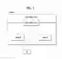
FIG. 3 is a diagram showing a control plane and a user plane of a radio interface protocol between a UE and an E-UTRAN based on a 3GPP radio access network standard. The control plane refers to a path used for transmitting control messages used for managing a call between the UE and the E-UTRAN. The user plane refers to a path used for transmitting data generated in an application layer, e.g., voice data or Internet packet data.
A physical (PHY) layer of a first layer provides an information transfer service to a higher layer using a physical channel. The PHY layer is connected to a medium access control (MAC) layer located on the higher layer via a transport channel. Data is transported between the MAC layer and the PHY layer via the transport channel Data is transported between a physical layer of a transmitting side and a physical layer of a receiving side via physical channels. The physical channels use time and frequency as radio resources. In detail, the physical channel is modulated using an orthogonal frequency division multiple access (OFDMA) scheme in downlink and is modulated using a single carrier frequency division multiple access (SC-FDMA) scheme in uplink.
The MAC layer of a second layer provides a service to a radio link control (RLC) layer of a higher layer via a logical channel. The RLC layer of the second layer supports reliable data transmission. A function of the RLC layer may be implemented by a functional block of the MAC layer. A packet data convergence protocol (PDCP) layer of the second layer performs a header compression function to reduce unnecessary control information for efficient transmission of an Internet protocol (IP) packet such as an IP version 4 (IPv4) packet or an IP version 6 (IPv6) packet in a radio interface having a relatively small bandwidth.
A radio resource control (RRC) layer located at the bottom of a third layer is defined only in the control plane. The RRC layer controls logical channels, transport channels, and physical channels in relation to configuration, re-configuration, and release of radio bearers (RBs). An RB refers to a service that the second layer provides for data transmission between the UE and the E-UTRAN. To this end, the RRC layer of the UE and the RRC layer of the E-UTRAN exchange RRC messages with each other.
One cell of the eNB is set to operate in one of bandwidths such as 1.25, 2.5, 5, 10, 15, and 20 MHz and provides a downlink or uplink transmission service to a plurality of UEs in the bandwidth. Different cells may be set to provide different bandwidths.
Downlink transport channels for transmission of data from the E-UTRAN to the UE include a broadcast channel (BCH) for transmission of system information, a paging channel (PCH) for transmission of paging messages, and a downlink shared channel (SCH) for transmission of user traffic or control messages. Traffic or control messages of a downlink multicast or broadcast service may be transmitted through the downlink SCH and may also be transmitted through a separate downlink multicast channel (MCH).
Uplink transport channels for transmission of data from the UE to the E-UTRAN include a random access channel (RACH) for transmission of initial control messages and an uplink SCH for transmission of user traffic or control messages. Logical channels that are defined above the transport channels and mapped to the transport channels include a broadcast control channel (BCCH), a paging control channel (PCCH), a common control channel (CCCH), a multicast control channel (MCCH), and a multicast traffic channel (MTCH).
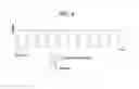
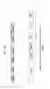
FIG. 4 is a view showing an example of a physical channel structure used in an E-UMTS system. A physical channel includes several subframes on a time axis and several subcarriers on a frequency axis. Here, one subframe includes a plurality of symbols on the time axis. One subframe includes a plurality of resource blocks and one resource block includes a plurality of symbols and a plurality of subcarriers. In addition, each subframe may use certain subcarriers of certain symbols (e.g., a first symbol) of a subframe for a physical downlink control channel (PDCCH), that is, an L1/L2 control channel. In FIG. 4, an L1/L2 control information transmission area (PDCCH) and a data area (PDSCH) are shown. In one embodiment, a radio frame of 10 ms is used and one radio frame includes 10 subframes. In addition, one subframe includes two consecutive slots. The length of one slot may be 0.5 ms. In addition, one subframe includes a plurality of OFDM symbols and a portion (e.g., a first symbol) of the plurality of OFDM symbols may be used for transmitting the L1/L2 control information. A transmission time interval (TTI) which is a unit time for transmitting data is 1 ms.
A base station and a UE mostly transmit/receive data via a PDSCH, which is a physical channel, using a DL-SCH which is a transmission channel, except a certain control signal or certain service data. Information indicating to which UE (one or a plurality of UEs) PDSCH data is transmitted and how the UE receive and decode PDSCH data is transmitted in a state of being included in the PDCCH.
For example, in one embodiment, a certain PDCCH is CRC-masked with a radio network temporary identity (RNTI) “A” and information about data is transmitted using a radio resource “B” (e.g., a frequency location) and transmission format information “C” (e.g., a transmission block size, modulation, coding information or the like) via a certain subframe. Then, one or more UEs located in a cell monitor the PDCCH using its RNTI information. And, a specific UE with RNTI “A” reads the PDCCH and then receive the PDSCH indicated by B and C in the PDCCH information.
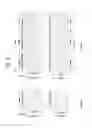
FIG. 5 is a block diagram of a communication apparatus according to an embodiment of the present invention.
The apparatus shown in FIG. 5 can be a user equipment (UE) and/or eNB adapted to perform the above mechanism, but it can be any apparatus for performing the same operation.
As shown in FIG. 5, the apparatus may comprises a DSP/microprocessor (110) and RF module (transceiver; 135). The DSP/microprocessor (110) is electrically connected with the transceiver (135) and controls it. The apparatus may further include power management module (105), battery (155), display (115), keypad (120), SIM card (125), memory device (130), speaker (145) and input device (150), based on its implementation and designer's choice.
Specifically, FIG. 5 may represent a UE comprising a receiver (135) configured to receive a request message from a network, and a transmitter (135) configured to transmit the transmission or reception timing information to the network. These receiver and the transmitter can constitute the transceiver (135). The UE further comprises a processor (110) connected to the transceiver (135: receiver and transmitter).
Also, FIG. 5 may represent a network apparatus comprising a transmitter (135) configured to transmit a request message to a UE and a receiver (135) configured to receive the transmission or reception timing information from the UE. These transmitter and receiver may constitute the transceiver (135). The network further comprises a processor (110) connected to the transmitter and the receiver. This processor (110) may be configured to calculate latency based on the transmission or reception timing information.
FIG. 6 illustrates an example of CCs and CA in the LTE-A system, which are used in embodiments of the present disclosure.
A 3GPP LTE system (conforming to Rel-8 or Rel-9) (hereinafter, referred to as an LTE system) uses Multi-Carrier Modulation (MCM) in which a single Component Carrier (CC) is divided into a plurality of bands. In contrast, a 3GPP LTE-A system (hereinafter, referred to an LTE-A system) may use CA by aggregating one or more CCs to support a broader system bandwidth than the LTE system. The term CA is interchangeably used with carrier combining, multi-CC environment, or multi-carrier environment.
In the present disclosure, multi-carrier means CA (or carrier combining). Herein, CA covers aggregation of contiguous carriers and aggregation of non-contiguous carriers. The number of aggregated CCs may be different for a DL and a UL. If the number of DL CCs is equal to the number of UL CCs, this is called symmetric aggregation. If the number of DL CCs is different from the number of UL CCs, this is called asymmetric aggregation. The term CA is interchangeable with carrier combining, bandwidth aggregation, spectrum aggregation, etc.
The LTE-A system aims to support a bandwidth of up to 100 MHz by aggregating two or more CCs, that is, by CA. To guarantee backward compatibility with a legacy IMT system, each of one or more carriers, which has a smaller bandwidth than a target bandwidth, may be limited to a bandwidth used in the legacy system.
For example, the legacy 3GPP LTE system supports bandwidths {1.4, 3, 5, 10, 15, and 20 MHz} and the 3GPP LTE-A system may support a broader bandwidth than 20 MHz using these LTE bandwidths. A CA system of the present disclosure may support CA by defining a new bandwidth irrespective of the bandwidths used in the legacy system.
There are two types of CA, intra-band CA and inter-band CA. Intra-band CA means that a plurality of DL CCs and/or UL CCs are successive or adjacent in frequency. In other words, the carrier frequencies of the DL CCs and/or UL CCs are positioned in the same band. On the other hand, an environment where CCs are far away from each other in frequency may be called inter-band CA. In other words, the carrier frequencies of a plurality of DL CCs and/or UL CCs are positioned in different bands. In this case, a UE may use a plurality of Radio Frequency (RF) ends to conduct communication in a CA environment.
The LTE-A system adopts the concept of cell to manage radio resources. The above-described CA environment may be referred to as a multi-cell environment. A cell is defined as a pair of DL and UL CCs, although the UL resources are not mandatory. Accordingly, a cell may be configured with DL resources alone or DL and UL resources.
For example, if one serving cell is configured for a specific UE, the UE may have one DL CC and one UL CC. If two or more serving cells are configured for the UE, the UE may have as many DL CCs as the number of the serving cells and as many UL CCs as or fewer UL CCs than the number of the serving cells, or vice versa. That is, if a plurality of serving cells are configured for the UE, a CA environment using more UL CCs than DL CCs may also be supported.
CA may be regarded as aggregation of two or more cells having different carrier frequencies (center frequencies). Herein, the term ‘cell’ should be distinguished from ‘cell’ as a geographical area covered by an eNB. Hereinafter, intra-band CA is referred to as intra-band multi-cell and inter-band CA is referred to as inter-band multi-cell.
In the LTE-A system, a Primacy Cell (PCell) and a Secondary Cell (SCell) are defined. A PCell and an SCell may be used as serving cells. For a UE in RRC_CONNECTED state, if CA is not configured for the UE or the UE does not support CA, a single serving cell including only a PCell exists for the UE. On the contrary, if the UE is in RRC_CONNECTED state and CA is configured for the UE, one or more serving cells may exist for the UE, including a PCell and one or more SCells.
Serving cells (PCell and SCell) may be configured by an RRC parameter. A physical-layer ID of a cell, PhysCellId is an integer value ranging from 0 to 503. A short ID of an SCell, SCellIndex is an integer value ranging from 1 to 7. A short ID of a serving cell (PCell or SCell), ServeCellIndex is an integer value ranging from 1 to 7. If ServeCellIndex is 0, this indicates a PCell and the values of ServeCellIndex for SCells are pre-assigned. That is, the smallest cell ID (or cell index) of ServeCellIndex indicates a PCell.
A PCell refers to a cell operating in a primary frequency (or a primary CC). A UE may use a PCell for initial connection establishment or connection reestablishment. The PCell may be a cell indicated during handover. In addition, the PCell is a cell responsible for control-related communication among serving cells configured in a CA environment. That is, PUCCH allocation and transmission for the UE may take place only in the PCell. In addition, the UE may use only the PCell in acquiring system information or changing a monitoring procedure. An Evolved Universal Terrestrial Radio Access Network (E-UTRAN) may change only a PCell for a handover procedure by a higher-layer RRCConnectionReconfiguraiton message including mobilityControlInfo to a UE supporting CA.
An SCell may refer to a cell operating in a secondary frequency (or a secondary CC). Although only one PCell is allocated to a specific UE, one or more SCells may be allocated to the UE. An SCell may be configured after RRC connection establishment and may be used to provide additional radio resources. There is no PUCCH in cells other than a PCell, that is, in SCells among serving cells configured in the CA environment.
When the E-UTRAN adds an SCell to a UE supporting CA, the E-UTRAN may transmit all system information related to operations of related cells in RRC_CONNECTED state to the UE by dedicated signaling. Changing system information may be controlled by releasing and adding a related SCell. Herein, a higher-layer RRCConnectionReconfiguration message may be used. The E-UTRAN may transmit a dedicated signal having a different parameter for each cell rather than it broadcasts in a related SCell.
After an initial security activation procedure starts, the E-UTRAN may configure a network including one or more SCells by adding the SCells to a PCell initially configured during a connection establishment procedure. In the CA environment, each of a PCell and an SCell may operate as a CC. Hereinbelow, a Primary CC (PCC) and a PCell may be used in the same meaning and a Secondary CC (SCC) and an SCell may be used in the same meaning in embodiments of the present disclosure.
FIG. 6(a) illustrates a single carrier structure in the LTE system. There are a DL CC and a UL CC and one CC may have a frequency range of 20 MHz.
FIG. 6(b) illustrates a CA structure in the LTE-A system. In the illustrated case of FIG. 6(b), three CCs each having 20 MHz are aggregated. While three DL CCs and three UL CCs are configured, the numbers of DL CCs and UL CCs are not limited. In CA, a UE may monitor three CCs simultaneously, receive a DL signal/DL data in the three CCs, and transmit a UL signal/UL data in the three CCs.
If a specific cell manages N DL CCs, the network may allocate M (M N) DL CCs to a UE. The UE may monitor only the M DL CCs and receive a DL signal in the M DL CCs. The network may prioritize L (L≤M≤N) DL CCs and allocate a main DL CC to the UE. In this case, the UE should monitor the L DL CCs. The same thing may apply to UL transmission.
The linkage between the carrier frequencies of DL resources (or DL CCs) and the carrier frequencies of UL resources (or UL CCs) may be indicated by a higher-layer message such as an RRC message or by system information. For example, a set of DL resources and UL resources may be configured based on linkage indicated by System Information Block Type 2 (SIB2). Specifically, DL-UL linkage may refer to a mapping relationship between a DL CC carrying a PDCCH with a UL grant and a UL CC using the UL grant, or a mapping relationship between a DL CC (or a UL CC) carrying HARQ data and a UL CC (or a DL CC) carrying an HARQ ACK/NACK signal.
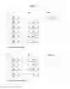
FIG. 7A is a diagram for MAC structure overview in a UE side, and FIG. 7B is a diagram for MAC PDU consisting of MAC header, MAC control elements, MAC SDUs and padding.
The MAC layer handles logical-channel multiplexing, hybrid-ARQ retransmissions, and uplink and downlink scheduling. It is also responsible for multiplexing/demultiplexing data across multiple component carriers when carrier aggregation is used.
The MAC provides services to the RLC in the form of logical channels. A logical channel is defined by the type of information it carries and is generally classified as a control channel, used for transmission of control and configuration information necessary for operating an LTE system, or as a traffic channel, used for the user data.
From the physical layer, the MAC layer uses services in the form of transport channels. A transport channel is defined by how and with what characteristics the information is transmitted over the radio interface. Data on a transport channel is organized into transport blocks. In each Transmission Time Interval (TTI), at most one transport block of dynamic size is transmitted over the radio interface to/from a terminal in the absence of spatial multiplexing. In the case of spatial multiplexing (MIMO), there can be up to two transport blocks per TTI.
Associated with each transport block is a Transport Format (TF), specifying how the transport block is to be transmitted over the radio interface. The transport format includes information about the transport-block size, the modulation-and-coding scheme, and the antenna mapping. By varying the transport format, the MAC layer can thus realize different data rates. Rate control is therefore also known as transport-format selection.
To support priority handling, multiple logical channels, where each logical channel has its own RLC entity, can be multiplexed into one transport channel by the MAC layer. At the receiver, the MAC layer handles the corresponding demultiplexing and forwards the RLC PDUs to their respective RLC entity for in-sequence delivery and the other functions handled by the RLC. To support the demultiplexing at the receiver, a MAC header, shown in FIG. 7B, is used.
To each RLC PDU, there is an associated sub-header in the MAC header. The sub-header contains the identity of the logical channel (LCID) from which the RLC PDU originated and the length of the PDU in bytes. There is also a flag indicating whether this is the last sub-header or not. One or several RLC PDUs, together with the MAC header and, if necessary, padding to meet the scheduled transport-block size, form one transport block which is forwarded to the physical layer.
In addition to multiplexing of different logical channels, the MAC layer can also insert the so-called MAC control elements into the transport blocks to be transmitted over the transport channels. A MAC control element is used for inband control signaling—for example, timing-advance commands and random-access response. Control elements are identified with reserved values in the LCID field, where the LCID value indicates the type of control information. Furthermore, the length field in the sub-header is removed for control elements with a fixed length.
A MAC PDU header consists of one or more MAC PDU subheaders; each subheader corresponds to either a MAC SDU, a MAC control element or padding.
A MAC PDU subheader consists of the six header fields R/R/E/LCID/F/L but for the last subheader in the MAC PDU and for fixed sized MAC control elements. The last subheader in the MAC PDU and subheaders for fixed sized MAC control elements consist solely of the four header fields R/R/E/LCID. A MAC PDU subheader corresponding to padding consists of the four header fields R/R/E/LCID.
MAC PDU subheaders have the same order as the corresponding MAC SDUs, MAC control elements and padding. MAC control elements are always placed before any MAC SDU.
Padding occurs at the end of the MAC PDU, except when single-byte or two-byte padding is required. Padding may have any value and the UE shall ignore it. When padding is performed at the end of the MAC PDU, zero or more padding bytes are allowed.
When single-byte or two-byte padding is required, one or two MAC PDU subheaders corresponding to padding are placed at the beginning of the MAC PDU before any other MAC PDU subheader. A maximum of one MAC PDU can be transmitted per TB per UE. A maximum of one MCH MAC PDU can be transmitted per TTI.
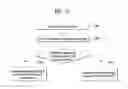
FIG. 8 is a diagram for exemplary Licensed-Assisted Access (LAA) scenarios.
Carrier aggregation with at least one SCell operating in the unlicensed spectrum is referred to as Licensed-Assisted Access (LAA). In LAA, the configured set of serving cells for a UE therefore always includes at least one SCell operating in the unlicensed spectrum, also called LAA SCell. Unless otherwise specified, LAA SCells act as regular SCells and are limited to downlink transmissions in this release.
If the absence of IEEE802.11n/11ac devices sharing the carrier cannot be guaranteed on a long term basis (e.g., by level of regulation), and for this release if the maximum number of unlicensed channels that E-UTRAN can simultaneously transmit on is equal to or less than 4, the maximum frequency separation between any two carrier center frequencies on which LAA SCell transmissions are performed should be less than or equal to 62 MHz. The UE is required to support frequency separation in accordance with 36.133.
LAA eNB applies Listen-Before-Talk (LBT) before performing a transmission on LAA SCell. When LBT is applied, the transmitter listens to/senses the channel to determine whether the channel is free or busy. If the channel is determined to be free, the transmitter may perform the transmission; otherwise, it does not perform the transmission. If an LAA eNB uses channel access signals of other technologies for the purpose of LAA channel access, it shall continue to meet the LAA maximum energy detection threshold requirement. The unlicensed band can be used for a Wi-Fi band or a Bluetooth band.
It has been agreed that the LTE CA framework is reused as the baseline for LAA, and that the unlicensed carrier can only be configured as SCell. The SCell over unlicensed spectrum may be downlink only or bi-directional with DL only scenario being prioritized in the SI. LAA only applies to the operator deployed small cells. Coexistence and fair sharing with other technologies is an essential requirement for LAA in all regions.
Regarding FIG. 8, LAA targets the carrier aggregation operation in which one or more low power SCells operate in unlicensed spectrum. LAA deployment scenarios encompass scenarios with and without macro coverage, both outdoor and indoor small cell deployments, and both co-location and non-co-location (with ideal backhaul) between licensed and unlicensed carriers. FIG. 8 shows four LAA deployment scenarios, where the number of licensed carriers and the number of unlicensed carriers can be one or more. As long as the unlicensed small cell operates in the context of the carrier aggregation, the backhaul between small cells can be ideal or non-ideal. In scenarios where carrier aggregation is operated within the small cell with carriers in both the licensed and unlicensed bands, the backhaul between macro cell and small cell can be ideal or non-ideal.
Scenario 1: Carrier aggregation between licensed macro cell (F1) and unlicensed small cell (F3).
Scenario 2: Carrier aggregation between licensed small cell (F2) and unlicensed small cell (F3) without macro cell coverage.
Scenario 3: Licensed macro cell and small cell (F1), with carrier aggregation between licensed small cell (F1) and unlicensed small cell (F3).
Scenario 4: Licensed macro cell (F1), licensed small cell (F2) and unlicensed small cell (F3). In this case, there is Carrier aggregation between licensed small cell (F2) and unlicensed small cell (F3). If there is ideal backhaul between macro cell and small cell, there can be carrier aggregation between macro cell (F1), licensed small cell (F2) and unlicensed small cell (F3). If dual connectivity is enabled, there can be dual connectivity between macro cell and small cell.
In the study to support deployment in unlicensed spectrum for the above scenarios, CA functionalities are used as a baseline to aggregate PCell/PSCell on licensed carrier and SCell on unlicensed carrier. When non-ideal backhaul is applied between a Macro cell and a small cell cluster in the Scenarios 3 and 4, small cell on unlicensed carrier has to be aggregated with a small cell on licensed carrier in the small cell cluster through ideal backhaul. The focus is to identify the need of and, if necessary, evaluate needed enhancements to the LTE RAN protocols applicable to the carrier aggregation in all the above scenarios.
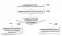
FIG. 9 is conceptual diagrams for diverse data applications for carrier aggregation.
The range of device types utilising current mobile networks continues to expand, encompassing smartphones, laptops, netbooks, tablets and embedded modems. Many are capable of running a wide variety of data applications, often in parallel. Such a diversity in device and application type creates a corresponding diversity in the traffic profiles that must be efficiently supported by the radio access networks on which they run.
Numerous applications require that an always-on mobile-broadband experience is seamlessly delivered and presented to the end user. Furthermore, many applications may be designed without specific consideration of the characteristics of cellular networks, and consequently may exhibit traffic profiles not well suited to those connections. When attempting to provide such always-on connectivity at the RAN level, trade-offs are often encountered between UE power consumption, user experience, data transfer latency, network efficiency and control plane signalling overhead. Furthermore, the optimum trade-off point may vary according to application characteristics, or their activity or status. Some specific issues were identified and discussed in RAN WG2 as part of TEI-10; creation of a work item would enable a more complete treatment of this topic.
Current trends indicate that the above issues will only increase in significance over the coming years. It is imperative therefore that the ability of LTE to efficiently handle and manage such traffic is continually improved.
A study item in TSG SA “non-MTC Mobile Data Applications Impacts” is ongoing and is investigating service scenarios and service enhancements for data applications. The work item “LTE RAN Enhancements for Diverse Data Applications” addresses RAN-level improvements within the existing RAN architecture.
In a carrier aggregation system comprising a plurality of cells according to the currently specification, there is no differentiation between different cells. That is, all cells aggregated to a UE are assumed to have same or similar characteristics. UL grants from different cells are served equally, i.e. there is no differentiation between UL grants from different cells. With diverse data applications, it may be required to map certain bearers or certain data to a specific cell, e.g. with better channel quality, or with better cell load situation.
In CA, the MAC functions are not optimized for diverse data applications. According to current MAC function, the SPS is not supported with CA, only single DRX pattern is supported, and Single value of sCellDeactivationTimer is used for all cells. For the optimized MAC operation with diverse data applications, it may be required to support cell-level MAC operation.
FIG. 9 discloses that different applications are transmitted to a respective cell mapped to a respective application. A radio bearer comprises a PDCP entity, a RLC entity and a MAC entity, and the MAC entity can be associated with a plurality of RLCs. That the MAC entity can be associated with a plurality of RLCs means that the MAC entity can be associated with a plurality of radio bearers. Considering a MAC function according to the current specification, the MAC entity doesn't need to distinguish different data from the different radio bearers.
For the Diverse Data Application, there is an event that the UE should transmit a specific data to a specific cell depending to type of data or type of bearers. However, considering a MAC function according to the current specification, because the MAC entity cannot tell the different applications, the UE needs a method for distinguishing different data from the different radio bearers when the UE generates a MAC PDU to be transmitted on the specific cell, which includes data to be transmitted to the specific cell.
Especially, in LAA configured with at least one unlicensed cell, in case that there is a mapping relation between a radio bearer and an unlicensed cell, the MAC entity needs to distinguish between data to be transmitted on the unlicensed cell and data not to be transmitted on the unlicensed cell when the MAC entity generates a MAC PDU.
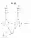
FIG. 10 is a conceptual diagram for receiving a signal for diverse data applications for carrier aggregation according to embodiments of the present invention.
This invention is that the UE transmits data of a bearer on a cell which is mapped to the bearer if the UE receives an indication which indicates the mapping between the bearer and the cell. If the UE does not receive the indication, the UE transmits data of the bearer on any cell for the bearer.
This case is that the indication is received with information for configuring a radio bearer.
When the UE configures a plurality of cells (S1001), the UE can receive the information for configuring a radio bearer (S1003).
Preferably, there can be at least one unlicensed cell among the plurality of cells.
In step of S1003, the UE can be configured by the network that a cell, among the plurality of cells, is mapped to a radio bearer.
Preferably, the indication indicates the mapping between a radio bearer and a cell.
Preferably, one radio bearer can be mapped to at least one cell, or one cell can be mapped to at least one radio bearer.
Preferably, the indication is received with or without the information for configuring the radio bearer.
Preferably, the indication is transmitted via RRC, PDCP, RLC, or MAC signal.
If the UE receives the indication which indicates that a cell is mapped to the radio bearer or the indication indicates at least one cell among the plurality of cells on which a data of the radio bearer is to be transmitted, the UE considers that the data of the radio bearer can only be transmitted on cell which is mapped to the radio bearer. In this case, the UE should transmit the data of the radio bearer on the at least one cell indicated by the indication (S1005). If the UE does not receive the indication, the UE considers that the data of the radio bearer can be transmitted on any cell. The UE can transmit the data of the radio bearer on any cell of the plurality of cells (S1007).
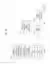
FIG. 11 is a conceptual diagram for receiving a signal for diverse data applications for carrier aggregation according to embodiments of the present invention.
This invention is that the UE transmits data of a bearer on a cell which is mapped to the bearer if the UE receives an indication which indicates the mapping between the bearer and the cell. If the UE does not receive the indication, the UE transmits data of the bearer on any cell for the bearer.
This case is that the indication is received with information for configuring a cell.
When the UE configures a plurality of radio bearers (S1101), the UE can receive the information for configuring a cell (S1103).
Preferably, the configured cell is a licensed cell or an unlicensed cell.
In step of S1103, the UE can be configured by the network that a radio bearer, among the plurality of radio bearers, is mapped to a cell.
Preferably, the indication indicates the mapping between a radio bearer and a cell.
Preferably, one radio bearer can be mapped to at least one cell, or one cell can be mapped to at least one radio bearer.
Preferably, the indication is received with or without the information for configuring the radio bearer.
Preferably, the indication is transmitted via RRC, PDCP, RLC, or MAC signal.
If the UE receives the indication which indicates that a radio bearer is mapped to the cell, or the indication indicates at least one radio bearer among the plurality of radio bearers of which a data is to be transmitted on the cell, the UE considers that a data of the radio bearer indicated by the indication on the cell. In this case, the UE should transmit the data of the radio bearer indicated by the indication on the cell (S1105). If the UE does not receive the indication, the UE considers that the data of any radio bearer among the plurality of radio bearers on the cell. The UE can transmit the data of any radio bearer among the plurality of radio bearers on the cell (S1107).
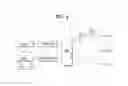
FIG. 12 is an example for receiving a signal for diverse data applications for carrier aggregation according to embodiments of the present invention.
When the UE generates a MAC PDU to be transmitted on the cell, the UE generates the MAC PDU by including only i) data of bearers which are mapped to the cell, and ii) data of bearers which are not mapped to any cell. Thus, the MAC PDU doesn't include data of bearers which are not mapped to the cell.
For example, the UE configures a plurality of cells, and receives information for configuring a plurality of radio bearers.
When the UE receives information for configuring a plurality of radio bearers, the UE also receives a first indication indicating a first cell among the plurality of cells on which a data of the first radio bearer can be transmitted and a second indication indicating a second cell among the plurality of cells on which a data of the second radio bearer can be transmitted.
When the UE configures the a plurality of radio bearers according to the information, a first type radio bearer is configured with a first indication, a second type radio bearer is configured with a second indication, and a third type radio bearer is configured without any indication.
When the UE generates a first MAC PDU to be transmitted on the first cell, the first MAC PDU can include a data from the first type bearer and a data from the third type bearer. When the UE generates a second MAC PDU to be transmitted on the second cell, the second the MAC PDU includes a data from the second type bearer and a data from the third type bearer.
The embodiments of the present invention described hereinbelow are combinations of elements and features of the present invention. The elements or features may be considered selective unless otherwise mentioned. Each element or feature may be practiced without being combined with other elements or features. Further, an embodiment of the present invention may be constructed by combining parts of the elements and/or features. Operation orders described in embodiments of the present invention may be rearranged. Some constructions of any one embodiment may be included in another embodiment and may be replaced with corresponding constructions of another embodiment. It is obvious to those skilled in the art that claims that are not explicitly cited in each other in the appended claims may be presented in combination as an embodiment of the present invention or included as a new claim by subsequent amendment after the application is filed.
In the embodiments of the present invention, a specific operation described as performed by the BS may be performed by an upper node of the BS. Namely, it is apparent that, in a network comprised of a plurality of network nodes including a BS, various operations performed for communication with an MS may be performed by the BS, or network nodes other than the BS. The term ‘eNB’ may be replaced with the term ‘fixed station’, ‘Node B’, ‘Base Station (BS)’, ‘access point’, etc.
The above-described embodiments may be implemented by various means, for example, by hardware, firmware, software, or a combination thereof.
In a hardware configuration, the method according to the embodiments of the present invention may be implemented by one or more Application Specific Integrated Circuits (ASICs), Digital Signal Processors (DSPs), Digital Signal Processing Devices (DSPDs), Programmable Logic Devices (PLDs), Field Programmable Gate Arrays (FPGAs), processors, controllers, microcontrollers, or microprocessors.
In a firmware or software configuration, the method according to the embodiments of the present invention may be implemented in the form of modules, procedures, functions, etc. performing the above-described functions or operations. Software code may be stored in a memory unit and executed by a processor. The memory unit may be located at the interior or exterior of the processor and may transmit and receive data to and from the processor via various known means.
Those skilled in the art will appreciate that the present invention may be carried out in other specific ways than those set forth herein without departing from essential characteristics of the present invention. The above embodiments are therefore to be construed in all aspects as illustrative and not restrictive. The scope of the invention should be determined by the appended claims, not by the above description, and all changes coming within the meaning of the appended claims are intended to be embraced therein.
INDUSTRIAL APPLICABILITY
While the above-described method has been described centering on an example applied to the 3GPP LTE system, the present invention is applicable to a variety of wireless communication systems in addition to the 3GPP LTE system.
Claims
1. A method for a user equipment (UE) operating in a wireless communication system, the method comprising:
configuring a plurality of cells;
receiving information for configuring a radio bearer; and
if the information includes an indication indicating at least one cell among the plurality of cells on which a data of the configured radio bearer is to be transmitted, transmitting a data of the radio bearer on the at least one cell indicated by the indication.
2. The method according to claim 1, wherein when the UE receives the indication, the UE considers that the data of the radio bearer can only be transmitted on the least one cell indicated by the indication.
3. The method according to claim 1, wherein if the information doesn't include the indication, the UE transmits the data of the radio bearer on any cell of the plurality of cells.
4. A method for a user equipment (UE) operating in a wireless communication system, the method comprising:
configuring a plurality of radio bearers;
receiving information for configuring a cell; and
if the information includes an indication indicating at least one radio bearer among the plurality of radio bearers of which a data is to be transmitted on the cell, transmitting a data of the radio bearer indicated by the indication on the cell.
5. The method according to claim 4, wherein when the UE receives the indication, the UE considers that only the data of the radio bearer indicated by the indication can be transmitted on the cell.
6. The method according to claim 4, wherein if the information doesn't include the indication, the UE transmits a data of any radio bearer among the plurality of radio bearers on the cell.
7. A method for a user equipment (UE) operating in a wireless communication system, the method comprising:
configuring a plurality of cells;
receiving information for configuring a plurality of radio bearers, wherein a first type radio bearer is configured with a first indication indicating a first cell among the plurality of cells on which a data of the first radio bearer can be transmitted, a second type radio bearer is configured with a second indication indicating a second cell among the plurality of cells on which a data of the second radio bearer can be transmitted, and a third type radio bearer is configured without any indication;
generating a first MAC PDU to be transmitted on the first cell, wherein the first MAC PDU includes a data from the first type bearer and a data from the third type bearer; and
generating a second MAC PDU to be transmitted on the second cell, wherein the second MAC PDU includes a data from the second type bearer and a data from the third type bearer.
8. A communication apparatus adapted to carry out the method of claim 1.
9. A communication apparatus adapted to carry out the method of claim 4.
10. A communication apparatus adapted to carry out the method of claim 7.
Images & Drawings included:

Sources:
- United States Patent and Trademark Office - verify current appl. status at the USPTO↗
Similar patent applications:
- » 20190261329
Method for receiving reference signal in wireless communication system and device therefor - » 20200304256
Method for receiving reference signal in wireless communication system and device therefor - » 20210105114
Method for receiving reference signal in wireless communication system and device therefor - » 20200260417
Method for transmitting or receiving signal in wireless communication system and device therefor - » 20190068341
Method for transmitting or receiving signal in wireless communication system and device therefor - » 20200221474
Method for transmitting or receiving signal in wireless communication system and device therefor - » 20200022188
Method for transmitting or receiving signal in wireless communication system and device therefor - » 20160381666
Method for transmitting and receiving signal in wireless communication system and device therefor - » 20180206261
Method for receiving a signal in wireless communication system and a device therefor - » 20200008236
Method for transmitting or receiving signal in wireless communication system and device therefor
Recent applications in this class:
- » 20250168652 2025-05-22
URBAN MOBILE NETWORK SYSTEM - » 20250150843 2025-05-08
URBAN MOBILE NETWORK SYSTEM - » 20250048120 2025-02-06
5G Native Architecture - » 20250008341 2025-01-02
METHODS AND APPARATUS FOR PROVIDING TIME VALID LOCATION BASED INFORMATION - » 20240276236 2024-08-15
METHODS AND APPARATUSES RELATING TO REPORTING OF USER PLANE INTERRUPTION TIMES - » 20240251253 2024-07-25
CONTROL APPARATUS, COMMUNICATION SYSTEM, CONTROL METHOD AND PROGRAM - » 20240236698 2024-07-11
METHODS AND APPARATUS FOR PROVIDING TIME VALID LOCATION BASED INFORMATION - » 20240163685 2024-05-16
BROADCAST OPERATIONS BY A SELECTED SUBSET OF ACCESS POINTS - » 20240107333 2024-03-28
GEOGRAPHICALLY REDUNDANT AND HIGH AVAILABILITY SYSTEM ARCHITECTURE FOR A HYBRID CLOUD CELLULAR NETWORK - » 20240080678 2024-03-07
WIRELESS INDUSTRIAL PROCESS FIELD DEVICE HAVING A PLURALITY OF TRANSCEIVERS
Recent applications for this Assignee:
- » 20250176346 2025-05-29
LED PANEL USING SEMICONDUCTOR LIGHT-EMITTING ELEMENT, PRODUCTION METHOD THEREFOR, AND DISPLAY DEVICE COMPRISING LED PANEL - » 20250176335 2025-05-29
DISPLAY DEVICE AND LIQUID CRYSTAL DISPLAY DEVICE - » 20250176122 2025-05-29
DISPLAY DEVICE - » 20250175737 2025-05-29
DISPLAY DEVICE - » 20250175645 2025-05-29
TRANSFORM-BASED IMAGE CODING METHOD AND DEVICE THEREFOR - » 20250175626 2025-05-29
VIDEO OR IMAGE CODING BASED ON MAPPING OF LUMA SAMPLES AND SCALING OF CHROMA SAMPLES - » 20250175611 2025-05-29
IMAGE CODING METHOD AND APPARATUS USING MOTION VECTOR DIFFERENCES - » 20250175610 2025-05-29
TRANSFORM-BASED IMAGE CODING METHOD AND DEVICE THEREFOR - » 20250175574 2025-05-29
DISPLAY DEVICE - » 20250173967 2025-05-29
ARTIFICIAL INTELLIGENCE DEVICE FOR 3D FACE TRACKING VIA ITERATIVE, DENSE AND DIRECT UV TO IMAGE FLOW AND METHOD THEREOF