Electrical connector having a shielding shell with laterally extending spring tangs
US20180212368A1
2018-07-26
15/877,347
2018-01-22
✅ Patent granted
US 10,297,957 B2
2019-05-21
-
-
Ross N Gushi
Wei Te Chung | Ming Chieh Chang
2038-01-22
Abstract:
An electrical connector includes: an insulative housing having a central receiving space; two rows of contacts secured to the housing and exposed inwardly to the receiving space; and a shielding shell enclosing the insulative housing, the shielding shell having a respective pair of spring tangs at each of two opposite walls thereof, each of the spring tang extending laterally in a cantilevered manner into the receiving space.
Assignee:
- FOXCONN INTERCONNECT TECHNOLOGY LIMITED 922 Grand Cayman, Cayman Islands
Applicant:
Interested in similar patents?
Get notified when new applications in this technology area are published.
Classification:
H01R12/72 IPC
Structural associations of a plurality of mutually-insulated electrical connecting elements, specially adapted for printed circuits, e.g. printed circuit boards [PCBs], flat or ribbon cables, or like generally planar structures, e.g. terminal strips, terminal blocks; Coupling devices specially adapted for printed circuits, flat or ribbon cables, or like generally planar structures; Terminals specially adapted for contact with, or insertion into, printed circuits, flat or ribbon cables, or like generally planar structures; Coupling devices for rigid printing circuits or like structures coupling with the edge of the rigid printed circuits or like structures
H01R12/724 » CPC further
Structural associations of a plurality of mutually-insulated electrical connecting elements, specially adapted for printed circuits, e.g. printed circuit boards [PCBs], flat or ribbon cables, or like generally planar structures, e.g. terminal strips, terminal blocks; Coupling devices specially adapted for printed circuits, flat or ribbon cables, or like generally planar structures; Terminals specially adapted for contact with, or insertion into, printed circuits, flat or ribbon cables, or like generally planar structures; Coupling devices for rigid printing circuits or like structures coupling with the edge of the rigid printed circuits or like structures coupling devices mounted on the edge of the printed circuits containing contact members forming a right angle
H01R13/6658 » CPC further
Details of coupling devices of the kinds covered by groups or -; Structural association with built-in electrical component with built-in electronic circuit on printed circuit board
H01R24/60 » CPC further
Two-part coupling devices, or either of their cooperating parts, characterised by their overall structure Contacts spaced along planar side wall transverse to longitudinal axis of engagement
H01R2107/00 » CPC further
Four or more poles
H05K2201/10189 » CPC further
Indexing scheme relating to printed circuits covered by; Details of components or other objects attached to or integrated in a printed circuit board; Types of components Non-printed connector
H05K2201/10189 » CPC further
Indexing scheme relating to printed circuits covered by; Details of components or other objects attached to or integrated in a printed circuit board; Types of components Non-printed connector
H01R13/66 IPC
Details of coupling devices of the kinds covered by groups or - Structural association with built-in electrical component
H01R13/6583 » CPC main
Details of coupling devices of the kinds covered by groups or -; Protective earth or shield arrangements on coupling devices, e.g. anti-static shielding ; High frequency shielding arrangements, e.g. against EMI [Electro-Magnetic Interference] or EMP [Electro-Magnetic Pulse]; Shield structure with resilient means for engaging mating connector with separate conductive resilient members between mating shield members
H01R13/642 » CPC further
Details of coupling devices of the kinds covered by groups or -; Means for preventing incorrect coupling by position or shape of contact members
H01R24/28 » CPC further
Two-part coupling devices, or either of their cooperating parts, characterised by their overall structure Coupling parts carrying pins, blades or analogous contacts and secured only to wire or cable
H01R13/658 IPC
Details of coupling devices of the kinds covered by groups or -; Protective earth or shield arrangements on coupling devices, e.g. anti-static shielding High frequency shielding arrangements, e.g. against EMI [Electro-Magnetic Interference] or EMP [Electro-Magnetic Pulse]
H01R12/57 » CPC further
Structural associations of a plurality of mutually-insulated electrical connecting elements, specially adapted for printed circuits, e.g. printed circuit boards [PCBs], flat or ribbon cables, or like generally planar structures, e.g. terminal strips, terminal blocks; Coupling devices specially adapted for printed circuits, flat or ribbon cables, or like generally planar structures; Terminals specially adapted for contact with, or insertion into, printed circuits, flat or ribbon cables, or like generally planar structures; Fixed connections for rigid printed circuits or like structures characterised by the terminals surface mounting terminals
H01R13/6582 » CPC further
Details of coupling devices of the kinds covered by groups or -; Protective earth or shield arrangements on coupling devices, e.g. anti-static shielding ; High frequency shielding arrangements, e.g. against EMI [Electro-Magnetic Interference] or EMP [Electro-Magnetic Pulse]; Shield structure with resilient means for engaging mating connector
Description
BACKGROUND OF THE INVENTION
1. Field of the Invention
The present invention relates to an electrical connector including an insulative housing having a central receiving space and a shielding shell having integral spring tangs extending laterally in a cantilevered manner into the receiving space.
2. Description of Related Art
China Patent No. 204464604 discloses a plug connector having a shielding shell and a separate pair of spring pieces located inside the shielding shell. Taiwan Patent No. 560961 discloses an electrical connector including a shielding shell having a pair of integral latches.
SUMMARY OF THE INVENTION
An electrical connector comprises: an insulative housing having a central receiving space; two rows of contacts secured to the housing and exposed inwardly to the receiving space; and a shielding shell enclosing the insulative housing, the shielding shell having a respective pair of spring tangs at each of two opposite walls thereof, each of the spring tang extending laterally in a cantilevered manner into the receiving space.
BRIEF DESCRIPTION OF THE DRAWING
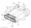
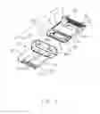
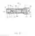
FIG. 1 is a front and top perspective view of an electrical connector in accordance with the present invention;
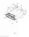
FIG. 2 is a rear and bottom perspective view of the electrical connector;
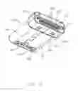
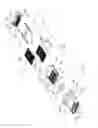
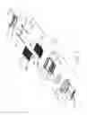
FIG. 3 is an exploded view of the electrical connector;
FIG. 4 is a view similar to FIG. 3 but from a different perspective;
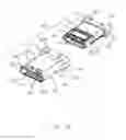
FIG. 5 is a further exploded view of the electrical connector in FIG. 3;
FIG. 6 is a view similar to FIG. 5 but from a different perspective;
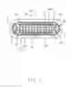
FIG. 7 is a cross-sectional view of the electrical connector taken along line A-A in FIG. 1; and
FIG. 8 is a cross-sectional view of the electrical connector taken along line B-B in FIG. 1.
DETAILED DESCRIPTION OF THE PREFERRED EMBODIMENT
Referring to FIGS. 1 to 8, an electrical connector 100 comprises an insulative housing, two rows of contacts 3 secured to the insulative housing, and a shielding shell 5 enclosing the insulative housing. The electrical connector 100 may further comprise a metal latch 4 and a pair of insulative sheets 6.
Referring to FIGS. 3-8, the insulative housing includes a body 1 and a base 2. The body 1 has a top wall 13, a bottom wall 14, and a pair of side walls 15 together surrounding a central receiving space 160. The body includes a front part 11 having a front opening and a rear part 12 having a rear opening. The top wall 13 has a recess 131 and the bottom wall 14 has a recess 141. Each of the top and bottom walls 13 and 14 has a respective pair of windows 17 at the front part 11. The recess 131 has a row of first slots 131 and dividers 132 and the recess 141 has a row of second slots 141 and dividers 142. The two rows of contacts 3 are exposed to the receiving space 160 through the first and second slots 131 and 141. Each of the pair of side walls 15 has a third slot 151.
Referring to FIGS. 2-6 and 8, the base 2 has a main portion 21 and a pair of blocks 22. The main portion 21 has plural protrusions 212, plural grooves 211, and a pair of fixing holes 221.
Referring to FIGS. 2-8, the contacts 2 include an upper row of contacts 310 and a lower row of contacts 320. Each contact 310 or 320 has a securing portion 302, a contacting portion 301, and a coupling portion 303. The contacting portion 301 has an apex 3011.
Referring to FIGS. 2 and 4-8, the metal latch 4 has a support 42, a pair of latching arms 41, and a pair of soldering legs 43. The latching arm 41 has an apex 411.
Referring again to FIGS. 1-8, the shielding shell 5 has a front tubular part 54 surrounding a receiving space 540 and a rear tubular part 56 surrounding a receiving space 560. The front tubular part 54 has a front end 541. Between the front tubular part 54 and the rear tubular part 56 is a tapered transition 55. The rear tubular part 56 has a rear end 561.
The shielding shell 5 includes a top wall/plate 51, a bottom wall/plate 52, and a pair of side walls/plates 53. Each of the top and bottom walls 51 and 52 has a respective pair of spring tangs 57 each extending laterally in a cantilevered manner into the receiving space 160 of the insulative housing through corresponding windows 17 of the insulative housing body 1. L-shaped corresponding windows/openings 573 are formed in the shielding shell 5, via which the spring tangs 57 are formed. Each spring tang 57 has an arm 571 and a guiding protrusion 572. The arms 571 of each pair of spring tangs 57 extend in opposite directions. The arm 571 and the protrusion 572 are substantially L-shaped. The shielding shell 5 further includes plural holes 562.
The electrical connector 100 is assembled in a known manner in this art with the contact coupling portions 303 and the latch soldering legs 43 ready to be terminated to an internal printed circuit board. In other embodiments, the two rows of contacts and the metal latch 4 may be insert molded with the insulative housing base 2. In the embodiment shown, all the spring tangs 57 are located entirely forwardly of the contacts 3.
Claims
What is claimed is:1. An electrical connector comprising:
an insulative housing having a central receiving space;
two rows of contacts secured to the housing and exposed inwardly to the receiving space; and
a shielding shell enclosing the insulative housing, the shielding shell having a respective pair of spring tangs at each of two opposite walls thereof, each of the spring tang extending laterally in a cantilevered manner into the receiving space.
2. The electrical connector as claimed in claim 1, wherein the spring tangs are located entirely forwardly of the contacts.
3. The electrical connector as claimed in claim 1, wherein each pair of spring tangs extend in opposite directions.
4. The electrical connector as claimed in claim 1, wherein each spring tang has a frontal guiding protrusion.
5. An electrical connector comprising:
a tubular insulative housing having opposite top and bottom walls with a central receiving space therebetween in a vertical direction, said receiving space forwardly communicating with an exterior in a front-to-back direction perpendicular to said vertical direction, each of said top and bottom walls forming a window communicating with the receiving space in the vertical direction;
two rows of contacts secured to the housing and respectively located in the top and bottom walls with contacting sections extending inwardly to the receiving space in the vertical direction;
a tubular shielding shell enclosing the insulative housing, the shielding shell having opposite top and bottom plates covering the corresponding top and bottom walls, respectively; and
a spring tang unitarily stamped and extending from each of said top and bottom plates and through the corresponding window into the receiving space in a cantilever manner.
6. The electrical connector as claimed in claim 5, wherein the spring tang are located in front of the contacts in said front-to-back direction.
7. The electrical connector as claimed in claim 5, wherein the spring tang extends in a transverse direction perpendicular to both said vertical direction and said front-to-back direction.
8. The electrical connector as claimed in claim 5, wherein each spring tang has a frontal guiding protrusion located at a free end and extending in the front-to-back direction so as to commonly form an L-shaped configuration.
9. The electrical connector as claimed in claim 8, wherein each of said top and bottom plates forms an L-shaped opening corresponding to the L-shaped configuration of the spring tang.
Images & Drawings included:
Sources:
- United States Patent and Trademark Office - verify current appl. status at the USPTO↗
Similar patent applications:
Recent applications in this class:
- » 20250202166 2025-06-19
SHIELDED PUSH-PULL PLUG HAVING SHIELDING SPRING - » 20240372301 2024-11-07
SHIELDED CONNECTOR ASSEMBLY - » 20240106172 2024-03-28
CONNECTOR AND ELECTRONIC DEVICE - » 20240106171 2024-03-28
MALE CONNECTOR, FEMALE CONNECTOR AND ELECTRICAL CONNECTOR ASSEMBLY - » 20240063584 2024-02-22
Electrical High-Current Connector - » 20230275375 2023-08-31
Round plug connector comprising a shield connection - » 20230268694 2023-08-24
SUBSTRATE CONNECTOR - » 20230246396 2023-08-03
CONNECTOR ASSEMBLY - » 20230238744 2023-07-27
Shielding means and high-speed electrical connector using the same - » 20230178939 2023-06-08
ELECTRONIC DEVICE AND SOCKET MODULE AND METAL SHIELDING FRAME THEREOF
Recent applications for this Assignee:
- » 20240199157 2024-06-20
METHOD OF CONTROLLING STATE OF ELECTRIC ASSIST BICYCLE, CONTROL SYSTEM, AND ELECTRONIC DEVICE - » 20240177887 2024-05-30
CORE WIRE AND METHOD OF MAKING SAME AND CABLE INCLUDING THE CORE WIRE - » 20240072477 2024-02-29
ELECTRICAL CONNECTOR WITH IMPROVED CONTACTS - » 20240055792 2024-02-15
Electrical connector having an angled part and a U-shaped plate together defining a tubular structure - » 20230352880 2023-11-02
ELECTRICAL CONNECTOR WITH IMPROVED INSERTING MEMBER - » 20230335934 2023-10-19
ELECTRICAL CONNECTOR - » 20230307870 2023-09-28
Electrical connector assembly having improved locking elements - » 20230283018 2023-09-07
ELECTRICAL CONNECTOR ASSEMBLY WITH IMPROVED TERMINALS - » 20230268679 2023-08-24
Electrical connector assembly - » 20230238732 2023-07-27
ELECTRICAL CONNECTOR ASSEMBLY HAVING A METAL PLATE FOR MOUNTING A CONNECTOR TO A HOUSING