System for connection and fitting method between modules for floor coverings
US20180223539A1
2018-08-09
15/747,701
2016-07-29
✅ Patent granted
US 10,287,778 B2
2019-05-14
WO; PCT/PT2016/050019; 20160729
WO; WO2017/018900; 20170202
Basil S Katcheves
Ladas & Parry, LLP
2036-07-29
Abstract:
The present invention relates to a system for connecting and a fitting method between modules for floor covering. The system comprises a female element (1) and a male element (2) connected to the floor modules and interlinked. The female element (1) consists of a major plate of the female element (1.1), track (1.2), edge (1.3), notches (1.3.1) (1.3.2), superior plate of the female element (1.4) and a groove (1.5). The male element (2) consists of a major plate of the male element (2.1), inferior plate (2.2), two protrusions, minor plate of the male element (2.3) and a latch (2.3.1).
Inventors:
- Nuno Miguel SIMÕES VICENTE 1 🇵🇹 Sintra, Portugal
- Nuno Miguel SIMÕES VICENTE 1 🇵🇹 Almada, Portugal
- Nuno Miguel Simões Vicente 1 🇵🇹 Sintra, Portugal
Applicant:
Interested in similar patents?
Get notified when new applications in this technology area are published.
Classification:
E04F15/02038 » CPC main
Flooring; Flooring or floor layers composed of a number of similar elements characterised by tongue and groove connections between neighbouring flooring elements
E04F2201/0123 » CPC further
Joining sheets or plates or panels; Joining sheets, plates or panels with edges in abutting relationship by moving the sheets, plates or panels parallel to the abutting edges
E04F2201/0138 » CPC further
Joining sheets or plates or panels; Joining sheets, plates or panels with edges in abutting relationship by moving the sheets, plates or panels perpendicular to the main plane
E04F2201/049 » CPC further
Joining sheets or plates or panels; Other details of tongues or grooves with tongues or grooves comprising elements which are not manufactured in one piece with the sheets, plates or panels but which are permanently fixedly connected to the sheets, plates or panels, e.g. at the factory wherein the elements are made of organic plastics with or without reinforcements or filling materials
E04F15/02 IPC
Flooring Flooring or floor layers composed of a number of similar elements
E04B2/00 IPC
Walls, e.g. partitions, for buildings; Wall construction with regard to insulation; Connections specially adapted to walls
Description
FIELD OF THE INVENTION
The present invention generally relates to the use of modular indoor or outdoor floorings, more specifically to a system for connecting and method of fitting together the modules that constitute the floor covering by means of male and female elements, which are not part of the modules and that are coupled to them.
BACKGROUND OF THE INVENTION
Modular systems for floor coverings have been well known since long. There is a huge variety of documents that refer to them, whether coverings made of natural materials such as wood or cork or made of synthetic or artificial materials.
The most classical method for fixing the modules to the floor consists of placing an aggregate material immediately above the floor upon which the covering is to be placed. This method has several disadvantages, being one of them the fact that the modules are easily damaged as upon fixing, any expansion or shrinkage which is common in any material, will cause the appearance of cracks and deformations. Therefore, the need for replacement of the modules becomes more pressing, which is also made difficult by the fact that the modules are fixed to the floor.
In response to this problem, coverings in which the modules fit together by means of solutions involving a male member and a female member have begun to emerge. Several documents relating to this solution may be mentioned, for example, WO2001098604 document disclosing a “floor covering with coupling means” or FR2917761 document disclosing a “Removable floor, for example, for a dance hall, with connections and cooperating interlocking units with each adjacent modular element”, or still the EP2010733 document that mentions a “Connection system for a mobile floor”.
Additionally, document WO2006113228 “Sub-flooring assembly and method” refers to an assembly comprised of sections that include male elements and female elements at the ends of the sections and also discloses the method of assembling the sections.
The assembly disclosed in the cited document differs from the present invention in the way that the male element and the female element are both present in the same section, while in the present invention the male element and female element are in different sections. The method to assembly the sections also differs from the method disclosed in the present invention.
Other existing solutions, which are also mentioned in several documents, involve the placement of a support structure immediately above the floor, being the modules made to fit in this structure. Refer to the WO2010079462 document featuring a “Modular floor system” and US2009249732 document that mentions a “modular floor system”.
BENEFITS OF THE INVENTION
However, all methods described above have the disadvantage that, in order to implement the above stated solutions the modules will have to be manufactured with embedded locking systems, which makes the solutions costlier.
The main advantage of the solution presented in this invention is to provide a solution that can be adapted to any existing floor type, since the connection between modules is achieved by fitting two elements, a male and a female element, which are not embedded in the modules, and that are coupled to them being fixed by a fastener system.
BRIEF DESCRIPTION OF THE DRAWINGS
These and other features are to be easily understood by the accompanying drawings, which should be taken as examples only and are not to be considered as limiting of its scope. For illustrative purposes some of the measurements of the elements of drawings may be exaggerated and not drawn to scale. The absolute and relative dimensions do not match actual relations for carrying out the invention.
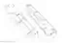
FIG. 1 shows a top view of the fitting between the female (1) and the male (2) elements for connection between floor modules.
FIG. 2 shows a bottom view of the fitting between the female (1) and the male (2) elements for connection between floor modules, where it can be seen that the latch (2.3.1) of the male element (2) fits in the groove (1.5) of the female element (1).
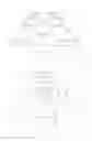
FIG. 3 shows a top front view of the male element (2) for connection between floor modules.
FIG. 4 shows a top rear view of the male element (2) for connection between floor modules.
FIG. 5 shows a bottom front view of the male element (2) for connection between floor modules.
FIG. 6 shows a top view of the male element (2) for connection between floor modules.
FIG. 7 shows a side view of the male element (2) for connection between floor modules.
FIG. 8 shows a side view of the male element (2) for connection between floor modules, in which protrusions (2.2.1) (2.2.2) are visible.
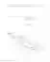
FIG. 9 shows a front view of the female element (1) for connection between floor modules.
FIG. 10 shows a top front view of the female element (1) for connection between floor modules.
FIG. 11 shows a side view of the female element (1) for connection between floor modules.
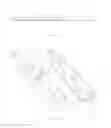
FIG. 12 shows a top view of the locking method of the male element (2) into the female element (1).
FIG. 13 shows a bottom view of the locking method of the male member (2) into the female element (1).
Their various components are visible in the figures: female element (1), major plate of the female element (1.1), track (1.2), edge (1.3), notch (1.3.1), notch (1.3.2), superior plate of the female element (1.4), groove (1.5), male element (2), major plate of the male element (2.1), inferior plate (2.2), protrusion (2.2.1), protrusion (2.2.2), minor plate of the male element (2.3) and latch (2.3.1).
DETAILED DESCRIPTION OF THE INVENTION
Expressions such as: “substantially parallelepiped”, “substantially cylindrical”, “substantially rectangular trapezoidal” shall be construed as preferred embodiments for carrying out the invention since it can operate with other embodiments. By “substantially horizontal”, “substantially vertical”, “substantially coplanar”, “substantially parallel”, “substantially equidistant”, “substantially aligned” shall be construed as preferred positions for carrying out the invention since it can operate with other positions.
Such terms as “sidewall”, “lower surface”, “upper surface”, “adjacent”, “inverted”, “end in the longitudinal direction,” “opposite end” used in the description are intended only for descriptive purposes and are not intended necessarily for describing relative positions. It is to be noted that the terms are used interchangeably in appropriate circumstances and that the embodiments of the invention described herein are capable of working in other orientations other than those herein described or illustrated. The terms “sidewall”, “lower surface”, “upper surface”, are the positions perceived by an observer facing the modules which make part the present disclosure.
The present disclosure relates to a connection system and a method for fitting together modules that make up the flooring covering.
This system is composed of a female element (1) and a male element (2) connected to the floor modules, and which are interlocked between each other.
The female element (1) and the male element (2) are manufactured in any suitable material for this purpose, particularly polyamide or any other polymeric based material. These materials are characterized by high resistance to stress, which is essential to the proper functioning of the system, which ensures the durability thereof.
In order to better understand the apparatus of this invention, in an embodiment thereof, FIGS. 3, 4, 5, 6, 7 and 8 are reversed, i.e., the upper surface is the one that comes in contact with the ground.
According to FIGS. 3, 4, 5, 6, 7 and 8 the male element (2) comprises:
-
- major plate of the male element (2.1)
- that presents
- a substantially parallelepiped shape,
- a length between 0.01 m and 1 m, more specifically between 0.1 m and 0.5 m, more specifically 0.3 m,
- a width of between 0.005 m and 0.25 m, more specifically 0.01 m and 0.05 m, more specifically 0.03 m,
- a height of between 0.001 m and 0.25 m, more specifically from 0.005 m and 0.05 m, more specifically 0.015 m;
- that presents
- an inferior plate (2.2)
- wherein
- one of the side walls in the longitudinal direction merges with one of the side walls in the longitudinal direction of the major plate of the male element (2.1),
- the side wall in the longitudinal direction opposite the side wall in the longitudinal direction merges with the major plate of the male element (2.1), being substantially vertically coplanar and which merges with one of the side walls in the longitudinal direction of the minor plate of the male element (2.3),
- being
- the wall at one of the ends in the longitudinal direction substantially vertically coplanar and that merges with the wall at one of the ends in the longitudinal direction of the minor plate of the male element (2.3),
- the upper surface substantially horizontally coplanar with the upper surface of the major plate of the male element (2.1),
- and having
- a substantially parallelepiped shape,
- a length between 0.01 m and 1 m, more specifically between 0.05 m and 0.5 m, more specifically 0.1758 m,
- a width of between 0.005 m and 0.25 m, more specifically 0.01 m and 0.1 m, more specifically 0.03 m,
- a height of between 0.0001 m and 0.1 m, more specifically between 0.0005 m and 0.05 m, more specifically 0.005 m,
- two protrusions (2.2.1) (2.2.2) for fitting the notches (1.3.1) (1.3.2) of the edge (1.3) of the female element (1);
- wherein
- a minor plate of the male element (2.3)
- being
- one of the walls at the ends in the longitudinal direction substantially vertically coplanar and that merges with the inferior plate (2.2) having the corners cut at the opposite end,
- one of the side walls in the longitudinal direction substantially coplanar and which merges laterally with the inferior plate (2.2),
- that presents
- a substantially parallelepiped shape,
- a length between 0.01 m and 1 m, more specifically between 0.05 m and 0.5 m, more specifically 0.2158 m,
- a width of between 0.005 m and 0.5 m, more specifically between 0.01 m and 0.1 m, more specifically 0.0243 m,
- a height of between 0.0001 m and 0.1 m, more specifically between 0.0005 m and 0.05 m, more particularly 0.0067 m,
- and which includes
- a latch (2.3.1) that fits in the groove (1.5) of the female element (1)
- which begins on the vertical plane passing through the vertical wall of the end in the longitudinal direction of the inferior plate (2.2) opposite the vertical wall of the end in the longitudinal direction that merges with the major plate of the male element (2.1),
- and having
- a length between 0.005 m and 0.2 m, more specifically 0.01 m and 0.1 m, more specifically 0.04 m,
- a width of between 0.005 m and 0.5 m, more specifically between 0.01 m and 0.1 m, more specifically 0.0243 m,
- a height of between 0.0001 m and 0.1 m, more specifically between 0.0005 m and 0.05 m, more specifically 0.0067 m.
- a latch (2.3.1) that fits in the groove (1.5) of the female element (1)
- being
- major plate of the male element (2.1)
The major plate of the male element (2.1) and the minor plate of the male element (2.3) have substantially equidistant holes between each other with a substantially cylindrical shape for placing the fastener elements at the lower surface of the floor modules.
According to FIGS. 9, 10 and 11 the female element (1) comprises:
-
- a major plate of the female element (1.1)
- that presents
- a substantially parallelepiped shape,
- a length between 0.01 m and 1 m, more particularly 0.05 m and 0.5 m, more specifically 0.3 m,
- a width of between 0.005 m and 0.5 m, more specifically between 0.01 m and 0.1 m, more specifically 0.03 m,
- a height of between 0.005 m and 0.5 m, more specifically between 0.01 m and 0.1 m, more specifically 0.015 m;
- that presents
- a track (1.2)
- demarcated on one of the lateral ends by the major plate of the female element (1.1) and on the opposite lateral end by the edge (1.3),
- and having
- a substantially rectangular trapezoidal shape, with a substantially horizontal upper surface,
- a length between 0.05 m and 1.5 m, more specifically between 0.1 m and 0.5 m, more specifically 0.175 m,
- a width of between 0.005 m and 0.25 m, more specifically between 0.01 m and 0.075 m, more specifically 0.02 m,
- a height of between 0.001 m and 0.1 m, more specifically between 0.003 m and 0.01 m, more specifically 0.0063 m on the edge adjacent to the major plate of the female element (1.1),
- a height of between 0.0005 m and 0.1 m, more specifically between 0.001 m and 0.01 m, more specifically 0.0035 m on the adjacent border to the edge (1.3),
- an edge (1.3)
- that presents
- a length between 0.05 m and 1 m, more specifically between 0.1 m and 0.5 m, more specifically 0.175 m,
- a width of between 0.001 m and 0.25 m, more specifically between 0.001 m and 0.1 m, more specifically 0.005 m,
- a height of between 0.001 m and 0.1 m, more specifically between 0.005 m and 0.02 m, more specifically 0.0085 m,
- two notches (1.3.1) (1.3.2) to be fitted in the protrusions (2.2.1) (2.2.2) of the male element (2);
- superior plate of the female element (1.4)
- substantially coplanar and which merges with the major plate of the female element (1.1), hollow in its inside, no bottom wall and having a groove (1.5) on the wall at the end in the longitudinal direction merging with the track (1.2) to fit the latch (2.3.1) of the male element (2),
- and having
- a substantially parallelepiped shape,
- a length between 0.05 m and 1 m, more specifically between 0.1 m and 0.5 m, more specifically 0.125 m,
- a width of between 0.005 m and 0.25 m, more specifically between 0.01 m and 0.075 m, more specifically 0.025 m,
- a height of between 0.0005 m and 0.05 m, more specifically between 0.001 m and 0.01 m, more specifically 0.003 m.
- that presents
- a major plate of the female element (1.1)
The major plate of the female element (1.1) exhibits substantially equidistant holes between each other with a substantially cylindrical shape for placing of the fastener elements to the lower surface of the floor modules.
Method of Fitting Male and Female Elements
According to FIGS. 12 and 13, in order to couple the female element (1) with the male element (2), the female element (1) and the male element (2) shall have to be positioned in substantially parallel planes, and the minor plate of the male element (2.3) substantially aligned with the track (1.2).
Then the male element (2) must be displaced so that the minor plate of the male element (2.3) gets in touch with the track (1.2), being the latch (2.3.1) substantially coplanar with groove (1.5). Simultaneously, the edge (1.3) should fit in the space between the side wall of the inferior plate (2.2) and the side wall of the major plate of the male element (2.1).
The male element (2) must be pushed until the latch (2.3.1) enters the groove (1.5), this movement should continue until the latch (2.3.1) is completely under the superior plate of the female element (1.4). This fact occurs when the vertical wall of the superior plate of the female element (1.4) immediately above the groove (1.5) comes into contact with the vertical wall of the inferior plate (2.2) closest to the latch (2.3.1). At this time, the protrusion (2.2.1) of the inferior plate (2.2) will sit and fit in the notch (1.3.2) of the edge (1.3) and the protrusion (2.2.2) of the inferior plate (2.2) will sit and fit in the notch (1.3.1) of the edge (1.3).
Claims
1. A system for connection of modules comprising a floor covering composed of a female element and a male element, wherein
the female element comprises:
a major plate
that presents
a substantially parallelepiped shape;
a superior plate;
substantially coplanar, and which merges with the major plate of the female element, which is hollow inside, without a bottom wall and having a groove on the end wall in the longitudinal direction that joins together with the plate to fit in the latch of the male element,
and having
a substantially parallelepiped shape;
the male element comprising:
a major plate
that presents
a substantially parallelepiped shape;
an inferior plate,
wherein
one of the side walls of the major plate of the male element in the longitudinal direction merges with one of the side walls in the longitudinal direction of the major plate of the male element,
the side wall in the longitudinal direction opposite the side wall in the longitudinal direction merging with the major plate of the male element, and being substantially vertically coplanar and merging with one of the side walls in the longitudinal direction of the plate,
being
the wall of one of the ends in the longitudinal direction substantially vertically coplanar and merging with the wall of one of the ends in the longitudinal direction of the minor plate of the male element,
the upper surface being substantially horizontally coplanar with the upper surface of the major plate of the male element
and having
a substantially parallelepiped shape
the minor plate of the male element being
one of the end walls in the longitudinal direction substantially vertically coplanar and that merging with the inferior plate having the corners cut at the opposite end,
one of the side walls in the longitudinal direction being substantially coplanar and merging laterally with the inferior plate
that presents
a substantially parallelepiped shape
and which includes
a latch for fitting in the groove of the female element
which begins
on the vertical plane passing through the vertical end wall in the longitudinal direction of the inferior plate opposite the vertical end wall in the longitudinal direction merging with the major plate of the male element
wherein:
the female element comprises:
a track
demarcated on one of the lateral ends by a major plate of the female element and on the opposite lateral end by the edge
and having
a substantially rectangular trapezoidal shape, with a substantially horizontal upper surface
an edge
that presents
notches for fitting the protrusions of the male element;
the male element comprising:
an inferior plate having protrusions for fitting in the notches of the edge of the female element.
2. A system for connection of modules comprising the floor covering according to claim 1, wherein the female element and the male element belong to separate plates.
3. A system for connection of modules comprising the floor covering according to claim 1, wherein the major plate of the female element has substantially equidistant holes between each other, for placement of fasteners to the lower surface of the floor modules.
4. (canceled)
5. (canceled)
6. (canceled)
7. A system for connection of modules comprising the floor covering according to claim 1, wherein the major plate of the male element and the minor plate of the male element have substantially equidistant holes between each other, for placement of fasteners to the lower surface of the floor modules.
8. A system for connection of modules comprising the floor covering according to the previous claims, wherein the female element and the male element are connected to the floor modules, and interconnected with each other.
9. A system for connection of modules comprising the floor covering according to the previous claims wherein the female element and the male element are manufactured in any suitable material for this purpose, particularly polyamide or any other polymeric based material.
10. The blocking method of the female element and the male element of the system for connecting the modules that comprise the floor covering claimed in claim 1, comprising the following steps:
The female element and the male element are positioned in substantially parallel planes, and the minor plate of the male element is substantially aligned with the track;
The male element is displaced so that the minor plate of the male element gets in touch with the track, the latch being substantially coplanar with groove; simultaneously, the edge will fit in the space between the side wall of the inferior plate and the side wall of the major plate of the male element;
The male element is pushed and slides through the track until the latch fits in the groove, this movement should continue until the latch is completely under the superior plate of the female element, this fact occurring when the vertical wall of the superior plate of the female element immediately above the groove comes into contact with the vertical wall of the inferior plate closest to the latch; at this point the protrusion of the inferior plate rests on, and is coupled to, the notch of the edge and the protrusion of the inferior plate rests and couples with notch of the edge;
wherein the notches fitting the protrusions of the male element.
Images & Drawings included:


Sources:
- United States Patent and Trademark Office - verify current appl. status at the USPTO↗
Recent applications in this class:
- » 20250277372 2025-09-04
SET OF FLOOR PANELS - » 20250270821 2025-08-28
PANEL WITH LOCKING DEVICE - » 20250270820 2025-08-28
FLOOR PANEL FOR FORMING A FLOOR COVERING - » 20250270819 2025-08-28
VERTICAL JOINT SYSTEM AND ASSOCIATED SURFACE COVERING SYSTEM - » 20250263940 2025-08-21
PANEL AND METHOD FOR MANUFACTURING SUCH A PANEL - » 20250263939 2025-08-21
PANEL AND METHOD FOR MANUFACTURING SUCH A PANEL - » 20250263938 2025-08-21
FLOOR BOARD AND METHOD FOR MANUFACTURING SUCH FLOOR BOARDS - » 20250263937 2025-08-21
FLOOR PANELS AND METHOD FOR PRODUCING FLOOR PANELS AND CUTTING TOOLS USED THEREIN - » 20250263936 2025-08-21
FLOOR PANEL FOR FORMING A FLOOR COVERING - » 20250263935 2025-08-21
Decorative Article with Multilayered Porosity Base