Air filter for bleed valve assembly
US20180229174A1
2018-08-16
15/431,108
2017-02-13
✅ Patent granted
US 10,512,876 B2
2019-12-24
-
-
Minh Chau T Pham
Kinney & Lange, P.A.
2037-05-03
Abstract:
An air filter assembly includes an air filter element with a pleated filter and seals incorporated at either end to prevent contaminants from bypassing the filter. The air filter assembly includes a filter cover, first, second and third seals, and an air filter element with a large diameter and low micron rating.
Inventors:
- Josh Kamp 26 🇺🇸 Glastonbury, CT, United States
- James J. Mercier 1 🇺🇸 Enfield, CT, United States
Assignee:
- HAMILTON SUNDSTRAND CORPORATION 1,737 🇺🇸 Windsor Locks, CT, United States
Applicant:
Interested in similar patents?
Get notified when new applications in this technology area are published.
Classification:
B01D2271/02 » CPC further
Sealings for filters specially adapted for separating dispersed particles from gases or vapours Gaskets, sealings
B01D46/521 » CPC main
Filters or filtering processes specially modified for separating dispersed particles from gases or vapours; Particle separators, e.g. dust precipitators, using filters embodying folded corrugated or wound sheet material using folded, pleated material
F05D2260/607 » CPC further
Function; Fluid transfer Preventing clogging or obstruction of flow paths by dirt, dust, or foreign particles
B01D46/52 IPC
Filters or filtering processes specially modified for separating dispersed particles from gases or vapours Particle separators, e.g. dust precipitators, using filters embodying folded corrugated or wound sheet material
F02C6/08 » CPC further
Plural gas-turbine plants; Combinations of gas-turbine plants with other apparatus ; Adaptations of gas- turbine plants for special use; Gas-turbine plants providing heated or pressurised working fluid for other apparatus, e.g. without mechanical power output providing compressed gas the gas being bled from the gas-turbine compressor
B01D46/0047 » CPC further
Filters or filtering processes specially modified for separating dispersed particles from gases or vapours with flow guiding by feed or discharge devices for discharging the filtered gas
B01D2271/027 » CPC further
Sealings for filters specially adapted for separating dispersed particles from gases or vapours; Gaskets, sealings Radial sealings
B01D46/2411 » CPC further
Filters or filtering processes specially modified for separating dispersed particles from gases or vapours; Particle separators, e.g. dust precipitators, using rigid hollow filter bodies characterised by the physical shape or structure of the filtering element Filter cartridges
F01D17/105 » CPC further
Regulating or controlling by varying flow; Final actuators by passing part of the fluid
B01D39/10 IPC
Filtering material for liquid or gaseous fluids Filter screens essentially made of metal
B01D39/12 IPC
Filtering material for liquid or gaseous fluids; Filter screens essentially made of metal of wire gauze; of knitted wire; of expanded metal
B01D39/20 IPC
Filtering material for liquid or gaseous fluids; Other self-supporting filtering material ; Other filtering material of inorganic material, e.g. asbestos paper, metallic filtering material of non-woven wires
B01D46/24 IPC
Filters or filtering processes specially modified for separating dispersed particles from gases or vapours Particle separators, e.g. dust precipitators, using rigid hollow filter bodies
F01N3/022 IPC
Exhaust or silencing apparatus having means for purifying, rendering innocuous, or otherwise treating exhaust for cooling, or for removing solid constituents of, exhaust by means of filters characterised by specially adapted filtering structure, e.g. honeycomb, mesh or fibrous
F01N3/021 IPC
Exhaust or silencing apparatus having means for purifying, rendering innocuous, or otherwise treating exhaust for cooling, or for removing solid constituents of, exhaust by means of filters
F01D25/00 IPC
Component parts, details, or accessories, not provided for in, or of interest apart from, other groups
B01D46/00 IPC
Filters or filtering processes specially modified for separating dispersed particles from gases or vapours
F01D17/10 IPC
Regulating or controlling by varying flow Final actuators
F02C9/18 » CPC further
Controlling gas-turbine plants; Controlling fuel supply in air- breathing jet-propulsion plants; Control of working fluid flow by bleeding, bypassing or acting on variable working fluid interconnections between turbines or compressors or their stages
Description
BACKGROUND
The present disclosure relates generally to pneumatically actuated valves and more specifically to filters for pneumatically actuated valves in bleed air systems.
Aircraft engine bleed air from the compressor stage of the engine is often re-routed within the aircraft for a number of uses, including internal cooling of the engine, cross-starting a second engine, ice protection purposes, pneumatic actuators, and many other uses. Typically, bleed air must be conditioned or directed to be used in another system. Thus, bleed air valve assemblies are used to direct and control bleed air before use elsewhere in the aircraft. Specifically, bleed valve assemblies use air filters to sift bleed air.
Typical bleed air assemblies, as found in the art, are bleed air systems with valve filters constructed of wire mesh or sintered metal screens. For pneumatic valves, the wire mesh or sintered metal screen is installed into a bore and constructed top hat style. In this configuration, the valve flange is spring loaded to seat and secure the filter element. This configuration has limited filtration capacity due to the restricted diameter of the configuration. Additionally, the micron rating of the filter is limited, as the valve would clog too quickly. Finally, this type of prior art filter lifts against the spring load when it does clog, which results in particles bypassing the filter element altogether.
SUMMARY
An air filter assembly includes a filter cover, an air filter element with a diameter ranging between 1.400 and 1.420 inches, the air filter element having an absolute micron rating of 5 microns, a first seal sealingly engaged to the filter cover and to the air filter element, a second seal sealingly engaged to the filter cover and to the air filter element, and a third seal sealingly engaged to the air filter element and a housing near an inlet flow path.
A method of filtering incoming bleed air includes receiving bleed air from an engine, routing the bleed air through an inlet path, filtering the bleed air through an air filter element with an absolute micron rating of 5 microns, and delivering the bleed air through an outlet path.
BRIEF DESCRIPTION OF THE DRAWINGS
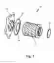
FIG. 1 is an exploded perspective view of a valve assembly.
FIG. 2 is a schematic cross section view of the valve assembly in FIG. 1.
DETAILED DESCRIPTION
Improved methods of filtration for pneumatic valves are increasingly important. Filtration contaminants continually clog valves resulting in decreased life of the valve system, and increased failure rates. A valve assembly with increased capacity having a larger diameter, smaller micron rating filter element, and a better sealing system can prevent breakdowns and is more efficient than prior designs.
FIG. 1 is an exploded perspective view of valve assembly 10. Assembly 10 includes filter cover 14, first seal 16, second seal 18, air filter element 20, and third seal 22. Filter cover 14 is metallic and can be made of a nickel alloy. Filter cover 14 is on an end of assembly 10, and keeps pressure inside valve assembly 10 in conjunction with housing 12 (shown in FIG. 2). Air filter assembly 10 can have a total length between about 2.025 inches and about 2.045 inches, depending on the exact needs of the system.
First and second seals 16, 18 are located between filter cover 14 and air filter element 20. First and second seals 16, 18 are C-seals, in one embodiment are made of metal and can be made of a nickel alloy, such as Inconel 718, for example. Seals 16, 18 are compressed between and seal to both the filter cover 14 and the air filter element 20 to prevent leakage of fluid. First seal 16 has a larger diameter than second seal 18.First seal 16 is configured to prevent external leakage of fluid or contaminants going through air filter element 20, while second seal 18 is configured to prevent bypass of contaminants around air filter element 20.
Air filter element 20 is linked to filter cover 14 by first and second seals 16, 18, on an outlet side of assembly 10. Opposite filter cover 14, air filter element 20 is connected to third seal 22 on an inlet side of assembly 10. Air filter element 20 can be made of a metallic alloy, such as a high-temperature cobalt or nickel based alloy with a minimum temperature capability of 1100 degrees Fahrenheit, and can have a length of about 1.645 inches, which allows for efficient filtering of contaminants. Air filter element 20 is a high capacity, pleated filter with an effective filtration area of 10 square inches minimum. The pleated nature of the filter allows greater surface area on which contaminants can stick, as compared to a flat filter found in the art. Traditional non-pleated filters only capture a certain size contaminant, while pleated filters have higher efficiency. Overall, the filter area of air filter element 20 is approximately thirty times larger than a typical air filter element used to filter bleed air. This allows filter element 20 to have a high surface area, increasing capacity of the assembly, and to maintain a long lifespan as it is used.
Additionally, air filter element 20 of assembly 10 uses a finer mesh filtration compared to the known art. A micron rating is typically used to indicate the ability of a fluid filter to remove contaminants by the size of the particles. Thus, a smaller micron rating means smaller particles can be removed when passing through a filter. Nominal micron ratings express the ability of a filter to capture particles of a specific size at an efficiency between 50% and 90%. In contrast, an absolute micron rating means the filter is capable of removing at least 98% of a particular size particle. In the art, absolute micron ratings of about 17 microns have been used in similar bleed air filter assemblies. In assembly 10, the mesh filtration has an absolute micron rating of 5. Thus, this filter catches significantly more contaminants than those in the prior art.
Air filter element 20 can have such a low absolute micron rating in part due to the diameter D2 (shown in FIG. 2) of assembly 10. Assembly 10 has a larger diameter D2 than other filters disclosed in the art. The diameter D2 of assembly 10 as a whole is between about 1.495 and about 1.505 inches. The diameter D1 of air filter element 20 is between 1.400 inches and 1.420 inches (shown in FIG. 2). Typically, prior art filters have diameters ranging from 0.225 inches to 0.710 inches. In assembly 10, if the diameter is too small, the life of assembly 10 is shortened, and air filter element 20 clogs quickly. But if the diameter is too large, outlet flow paths leading away from air filter element 20 are blocked. The length L1 of air filter element 20 is between 1.480 inches and 1.500 inches, shown in FIG. 2. Air filter assembly 10 has a length L2 between 2.025 inches and 2.045 inches (shown in FIG. 2).
Third seal 22 is also a metallic C-seal, located at an inlet of assembly 10. C-seals are a resilient metal seal that can be created to fit a particular diameter and system. Third seal 22 prevents contaminants from bypassing air filter element 20. Third seal 22 is connected to a valve housing 12 (shown in FIG. 2). Seals 16, 18 and 22 interface with air filter element 20 and a housing 12 to seal assembly 10. Seals 16, 18 and 22 incorporated at each end to prevent contaminants from bypassing assembly 10.
FIG. 2 is a schematic cross sectional view of the valve assembly in FIG. 1. Valve assembly 10 includes the same parts as FIG. 1, and additionally highlights fluid flow in assembly 10 by showing valve housing 12, inlet flow path 24, and first and second outlet flow paths 26, 28.
In valve assembly 10, filter cover 14, first seal 16, second seal 18, air filter element 20, and third seal 22 are surrounded by valve housing 23. Fluid enters assembly 10 through inlet flow path 24 (shown by incoming arrows). Typically, the fluid is highly contaminated bleed air from the compressor region of an engine. The fluid runs through a separator, which removes large debris (of sizes greater than 40 microns) before the fluid flows into assembly 10. Fluid flows through third seal 22 to air filter element 20, where it is filtered and contaminants are separated from the fluid. First and second outlet flow paths 26, 28 are made of circular drill paths (paths created through drill methods) designed to direct outgoing filtered fluid. Filtered outgoing fluid flows out first or second outlet flow paths 26, 28, to different locations, depending on the needs of the system.
Assembly 10 is highly efficient because of its large diameter, low micron rating filter element, and seal system which together better filter incoming bleed air and prevent leakage. There are several aspects to the design of assembly 10. First, the large diameter of the filter element allows for a high capacity of the valve system, improving the durability of the component. The filter element takes longer to clog due to the increased diameter. Second, the construction of the filter element allows for a lower micron rating, which protects downstream components and allows for longer life of the valve assembly. Finally, the valve system does not lift or allow for a flow path around the filter when the filter clogs. There is no axial plug load due to the sealing around the filter element.
The increased capacity and lifespan of the valve assembly is critical for several reasons. First, a valve assembly for use in bleed air control is a relatively expensive part, as it is a must be a brazed or welded assembly. Second, there is a high replacement cost factor; these parts are typically replaced at valve overhaul. Finally, protection of the air filter element allows for better control and life of the assembly as a whole.
Discussion of Possible Embodiments
The following are non-exclusive descriptions of possible embodiments of the present invention.
An air filter assembly includes a filter cover, an air filter element with a diameter ranging between 1.400 and 1.420 inches, the air filter element having an absolute micron rating of 5 microns, a first seal sealingly engaged to the filter cover and to the air filter element, a second seal sealingly engaged to the filter cover and to the air filter element, and a third seal sealingly engaged to the air filter element and a housing near an inlet flow path.
The assembly of the preceding paragraph can optionally include, additionally and/or alternatively, any one or more of the following features, configurations and/or additional components:
The air filter element comprises a high capacity pleated filter.
The air filter assembly has a length between 2.025 inches and 2.045 inches.
The air filter element has a length between 1.480 inches and 1.500 inches.
The air filter assembly has a diameter between 1.495 inches and 1.505 inches.
The air filter element is made of a material selected from the group consisting of nickel, cobalt or an alloy thereof.
The first, second and third seals are made of a material selected from the group consisting of nickel, cobalt or an alloy thereof.
The air filter assembly includes at least one circular drill path extending from a bleed air source to the air filter element.
The air filter assembly includes a first circular drill path extending from the air filter element to a first outlet.
The air filter includes a second circular drill path extending from the air filter element to a second outlet.
A method of filtering incoming bleed air includes receiving bleed air from an engine, routing the bleed air through an inlet path, filtering the bleed air through an air filter element with an absolute micron rating of 5 microns, and delivering the bleed air through an outlet path.
The method of the preceding paragraph can optionally include, additionally and/or alternatively, any one or more of the following features, configurations and/or additional components:
The method includes passing the bleed air through a separator with a rating of 40 microns prior to routing the bleed air through an inlet path.
The air filter element is sealed such that there is negligible leakage of bleed air out of the air filter element.
While the invention has been described with reference to an exemplary embodiment(s), it will be understood by those skilled in the art that various changes may be made and equivalents may be substituted for elements thereof without departing from the scope of the invention. In addition, many modifications may be made to adapt a particular situation or material to the teachings of the invention without departing from the essential scope thereof. Therefore, it is intended that the invention not be limited to the particular embodiment(s) disclosed, but that the invention will include all embodiments falling within the scope of the appended claims.
Claims
1. An air filter arrangement comprising:
a filter cover;
an air filter element with a diameter ranging between 1.400 and 1.420 inches, the air filter element having an absolute micron rating of 5 microns;
a first seal sealingly engaged to the filter cover and to the air filter element;
a second seal sealingly engaged to the filter cover and to the air filter element; and
a third seal sealingly engaged to the air filter element and a housing near an inlet flow path.
2. The air filter assembly of claim 1, wherein the air filter element comprises a high capacity pleated filter.
3. The air filter assembly of claim 1, wherein the air filter assembly has a length between 2.025 inches and 2.045 inches.
4. The air filter assembly of claim 1, wherein the air filter element has a length between 1.480 inches and 1.500 inches.
5. The air filter assembly of claim 1, wherein the air filter assembly has a diameter between 1.495 inches and 1.505 inches.
6. The air filter assembly of claim 1, wherein the air filter element is made of a material selected from the group consisting of nickel, cobalt or an alloy thereof.
7. The air filter assembly of claim 1, wherein the first, second and third seals are made of a material selected from the group consisting of nickel, cobalt or an alloy thereof.
8. The air filter assembly of claim 1, further comprising at least one circular drill path extending from a bleed air source to the air filter element.
9. The air filter assembly of claim 1, further comprising a first circular drill path extending from the air filter element to a first outlet.
10. The air filter assembly of claim 9, further comprising a second circular drill path extending from the air filter element to a second outlet.
11. A method of filtering incoming bleed air comprising:
receiving bleed air from an engine;
routing the bleed air through an inlet path;
filtering the bleed air through an air filter element with an absolute micron rating of 5 microns; and
delivering the bleed air through an outlet path.
12. The method of claim 11, further comprising passing the bleed air through a separator with a rating of 40 microns prior to routing the bleed air through an inlet path.
13. The method of claim 11, wherein the air filter element is sealed such that there is negligible leakage of bleed air out of the air filter element.
Images & Drawings included:


Sources:
- United States Patent and Trademark Office - verify current appl. status at the USPTO↗
Recent applications in this class:
- » 20250288934 2025-09-18
COOKING APPARATUS VENTILATION SYSTEM INCLUDING OIL-SMOKE COLLECTION FILTER - » 20250288933 2025-09-18
FILTER MATERIAL WITH MEMBRANE AND FILTER ELEMENT MADE OF SUCH FILTER MATERIAL - » 20250229208 2025-07-17
FRAMED AIR FILTER COMPRISING PLEATED FILTER ELEMENT WITH EDGE SEALS AND A PERIMETER SEAL - » 20250144555 2025-05-08
REUSABLE AIR FILTER SYSTEM AND METHOD - » 20250090988 2025-03-20
FOLDABLE FILTER WITH SUPPORT - » 20250083084 2025-03-13
AIR FILTER FOR SEVERE CHRONIC ASTHMATICS - » 20240382892 2024-11-21
FILTER-HOUSING INTERFACE DESIGNS FOR HEATING, VENTILATION, AND/OR AIR CONDITIONING SYSTEMS - » 20240325960 2024-10-03
Air Filtration Device And Method Of Use - » 20240269599 2024-08-15
ARCHED AIR FILTER - » 20240261716 2024-08-08
Round Filter Element
Recent applications for this Assignee:
- » 20210381779 2021-12-09
Method for manufacturing a curved heat exchanger using wedge shaped segments - » 20210381438 2021-12-09
In flight restart system and method for free turbine engine - » 20210123695 2021-04-29
Heat exchanger with spray nozzle - » 20200182559 2020-06-11
Heat exchanger riblet and turbulator features for improved manufacturability and performance - » 20200077538 2020-03-05
Heat exchange device in directed flow system - » 20190212074 2019-07-11
Method for manufacturing a curved heat exchanger using wedge shaped segments - » 20190060828 2019-02-28
Temperature controlled nitrogen generation system - » 20190010874 2019-01-10
In flight restart system and method for free turbine engine - » 20180306234 2018-10-25
Foil bearing with split key - » 20180237144 2018-08-23
Two mode system that provides bleed and outside air or just outside air