Stop for a rail of a longitudinally adjustable seat
US20180229625A1
2018-08-16
15/749,962
2016-08-03
✅ Patent granted
US 11,447,042 B2
2022-09-20
WO; PCT/EP2016/068483; 20160803
WO; WO2017/021427; 20170209
Jonathan Liu | Taylor L Morris
Marshall & Melhorn, LLC
2036-08-03
Abstract:
A stop (11, 11′), in particular an abutment for a longitudinal adjustment mechanism, includes a stop element (15, 15′) that can be placed in various positions. The stop element is configured to automatically lock into a retaining position.
Assignee:
- KEIPER SEATING MECHANISMS CO., LTD. 33 🇨🇳 Shanghai, China
Applicant:
Interested in similar patents?
Get notified when new applications in this technology area are published.
Classification:
B60N2/0705 » CPC further
Seats specially adapted for vehicles; Arrangement or mounting of seats in vehicles the seat or part thereof being movable, e.g. adjustable the whole seat being movable slidable; Slide construction characterised by its cross-section omega-shaped
B60N2/0806 » CPC further
Seats specially adapted for vehicles; Arrangement or mounting of seats in vehicles the seat or part thereof being movable, e.g. adjustable the whole seat being movable slidable characterised by the locking device with pin alignment systems, e.g. with at least one of a plurality of locking pins always aligned w.r.t. at least one of a plurality of pin-receiving elements
B60N2/07 IPC
Seats specially adapted for vehicles; Arrangement or mounting of seats in vehicles the seat or part thereof being movable, e.g. adjustable the whole seat being movable slidable Slide construction
B60N2/08 IPC
Seats specially adapted for vehicles; Arrangement or mounting of seats in vehicles the seat or part thereof being movable, e.g. adjustable the whole seat being movable slidable characterised by the locking device
B60N2/0727 » CPC main
Seats specially adapted for vehicles; Arrangement or mounting of seats in vehicles the seat or part thereof being movable, e.g. adjustable the whole seat being movable slidable; Slide construction; Constructive details Stop members for limiting sliding movement
B60N2/073 » CPC further
Seats specially adapted for vehicles; Arrangement or mounting of seats in vehicles the seat or part thereof being movable, e.g. adjustable the whole seat being movable slidable; Slide construction; Constructive details Reinforcement members preventing slide dislocation
B60N2/0722 » CPC further
Seats specially adapted for vehicles; Arrangement or mounting of seats in vehicles the seat or part thereof being movable, e.g. adjustable the whole seat being movable slidable; Slide construction Constructive details
B60R13/0206 » CPC further
Elements for body-finishing, identifying, or decorating; Arrangements or adaptations for advertising purposes; Trim mouldings Ledges; Wall liners for passenger compartments ; Roof liners Arrangements of fasteners and clips specially adapted for attaching inner vehicle liners or mouldings
B60R13/02 IPC
Elements for body-finishing, identifying, or decorating; Arrangements or adaptations for advertising purposes Trim mouldings Ledges; Wall liners for passenger compartments ; Roof liners
Description
CROSS REFERENCE TO RELATED APPLICATIONS
This application is a United States National Phase Application of International Application PCT/EP2016/068483, filed Aug. 3, 2016, and claims the benefit of priority under 35 U.S.C. § 119 of German Application 10 2015 214 775.4, filed Aug. 3, 2015, the entire contents of which are incorporated herein by reference.
FIELD OF THE INVENTION
The invention relates to a stop for a rail of a longitudinally displaceable seat, in particular of a vehicle seat, and to a rail for a longitudinal adjuster with such a stop.
BACKGROUND OF THE INVENTION
Stops, in particular end stops for a rail of a longitudinally displaceable seat are known from the prior art, wherein the end stop stops a displacement of the seat or shortens a travel distance.
SUMMARY OF THE INVENTION
It is an object of the present invention to specify a stop, which is improved over the prior art, for a rail of a longitudinally displaceable vehicle seat, and an improved rail with such a stop.
The object is achieved according to the invention with a stop which comprises a stop element which is variably positionable and automatically fixes itself.
For this purpose, the stop element has at least two protruding holding elements, of which one is angled in a hook shaped manner and the other is of pin shaped design. The stop element is therefore positionable in and pluggable into a rail by means of a fixing and plug in connection. For the fixing of the plug in connection, in particular the pin shaped holding element, a flexible fixing element, in particular a holding spring, is provided. The holding spring is configured as an omega spring. Alternatively, the pin shaped holding element can be is configured such that the latter fixes itself with a form fit and/or force fit connection. For this purpose, the pin shaped holding element is formed, for example, from a flexible material or is of flexible and profiled design at least on the outer side, and therefore a plug in and clamping connection is made possible.
The advantages achieved with the invention consist in particular in that a stop is configured such, when mechanically stressed, for example when a rail part, such as a plate, acts on the stop, a movement is reliably stopped. Furthermore, such a stop can be inserted and fixed variably in the rail. By this means, travel distances of differing length can be set.
The stop is in particular an end stop for a longitudinal adjustment device and comprises a stop element which is variably positionable and is formed in such a manner that it automatically fixes in a holding position.
For this purpose, the stop element, in one possible embodiment, is configured as a positioning and fixing element. In particular, the stop element is configured as a plug in and fixing element. In other words: the stop element is configured, in particular shaped, such that it first of all permits pre positioning and subsequently automatic fixing.
In one possible embodiment, the stop element has at least two protruding holding elements for the positioning, in particular pre positioning, and fixing. In this case, one of the holding elements is of hook shaped design. For example, one of the holding elements protrudes from the stop element, wherein the free protruding end is angled or bent. The other holding element is of pin shaped design. For example, the other holding element protrudes rectilinearly from the stop element in the form of a pin.
In a further embodiment, at least one of the holding elements is of such flexible design that a plug in and clamping connection is made possible. For example the flexible holding element is formed from a flexible material. Alternatively, the flexible holding element can be of flexible design at least on the outer side. For example, the flexible holding element can be formed from two materials, wherein at least the outer layer is formed from a flexible material, in particular a soft material, such as rubber or a plastic. By this means, the holding element can automatically be fixed at a position with a form fit and/or force fit connection.
Furthermore, at least one of the holding elements can be of profiled design on the outer side. Such a profiling improves the automatic fixing of the stop.
In addition, an, in particular separate, fixing element can be provided which is arrangeable with a form fit and/or force fit connection on the stop. By means of the fixing element, the stop can be fixed in addition to the automatic fixing.
In one possible embodiment, the fixing element is configured as a holding spring, in particular an omega spring. Alternatively, the fixing element can be configured as a leaf spring or another suitable element.
In an alternative embodiment, the fixing element is configured as a plug in element which is arrangeable with a form fit and/or force fit connection in the stop element. The installation is thereby simplified.
In addition, the fixing element can be produced simply and cost effectively. For example, the fixing element can be a plastics part, in particular an injection molded part. The fixing element can be formed, for example, from a thermoplastic elastomer, in particular polypropylene or polyethylene. Alternatively, the fixing element can also be a cast part composed of another material.
Furthermore, the fixing element is irreversibly arrangeable on or in the stop element, in particular irreversibly in a recess of the stop element. For example, the fixing element has at least one depression, and the stop element correspondingly has at least one protrusion, or vice versa. In particular, the fixing element has at least one depression, in particular a notch, score or groove, on the outer side, in particular on the end side. The stop element, in particular the recess of the stop element, correspondingly has at least one protrusion, in particular a rib, a web or a saw tooth rib. Alternatively, the fixing element can have a protrusion, and the stop element can correspondingly have a depression. The fixing element can be is configured such that the latter is arrangeable both irreversibly in the stop element and also automatically and irreversibly fixes the stop element in a holding position.
By means of such a fixing element which is held irreversibly in the stop element and automatically and irreversibly holds the stop element in a holding position, a simple stop which can be variably positioned and fixed is provided. In addition, the stop can absorb large forces.
The invention furthermore relates to a longitudinally adjustable pair of rails which comprises at least one stop, as previously described.
The stop is arrangeable here in a variably positionable and automatically fixable manner on a rail of the pair of rails. Installation is therefore simplified. In addition, such a stop can be simply retrofitted in existing longitudinal adjustment devices having pairs of rails.
In one possible embodiment, the stop forms an end stop. The stop can be arrangeable releasably here in an interior space between the rails of the pair of rails.
For the pre positioning and automatic fixing, at least two holding elements of the stop engage horizontally in the rails. One of the holding elements here can have a longer engagement than the other holding element. By this means, the stop is configured as a combined positioning and fixing element, wherein one of the holding elements serves for the positioning, in particular pre positioning, and the other holding element brings about fixing, in particular automatic fixing.
The invention furthermore relates to at least one longitudinal adjustment device with at least two pairs of rails, of which each pair of rails comprises at least one of the previously described stops.
Exemplary embodiments of the invention are explained in more detail with reference to drawings. The various features of novelty which characterize the invention are pointed out with particularity in the claims annexed to and forming a part of this disclosure. For a better understanding of the invention, its operating advantages and specific objects attained by its uses, reference is made to the accompanying drawings and descriptive matter in which preferred embodiments of the invention are illustrated.
BRIEF DESCRIPTION OF THE DRAWINGS
In the drawings:
FIG. 1 is a schematic side view of a vehicle seat comprising at least one pair of rails;
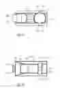
FIG. 2 is a schematic cross sectional view of an exemplary embodiment of a pair of rails with a stop positioned and fixed in a lower rail;
FIG. 3 is a schematic longitudinal sectional view of an exemplary embodiment of a pair of rails with a stop positioned in a lower rail;
FIG. 4 is a schematic top view an exemplary embodiment of a stop positioned in a lower rail;
FIG. 5 is a schematic cross sectional view of a further exemplary embodiment of a pair of rails with a stop positioned in a lower rail;
FIG. 6 is a schematic view of a further exemplary embodiment of a pair of rails with a stop positioned in a lower rail;
FIG. 7 is a schematic view of the further exemplary embodiment of a pair of rails with a stop positioned in a lower rail;
FIG. 8 is a schematic view of a further exemplary embodiment of the pair of rails with a stop positioned in a lower rail;
FIG. 9 is a schematic view of another exemplary embodiment of a stop with a separate fixing element;
FIG. 10 is a schematic view of the other exemplary embodiment of a stop with a separate fixing element;
FIG. 10A is a schematic sectional view of the other exemplary embodiment of a stop with a separate fixing element;
FIG. 10B is a schematic sectional view of the other exemplary embodiment of a stop with a separate fixing element;
FIG. 11 is a schematic view of the other exemplary embodiment of a stop with a separate fixing element;
FIG. 12 is a schematic view of the other exemplary embodiment of a stop with a separate fixing element;
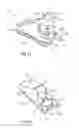
FIG. 13 is a schematic perspective view of an alternative exemplary embodiment of a stop with a separate fixing element;
FIG. 14 is a schematic perspective view of the alternative exemplary embodiment of a stop with a separate fixing element;
FIG. 15 is a schematic sectional view of the alternative exemplary embodiment of a stop with a separate fixing element;
FIG. 16 is a schematic sectional view of the alternative exemplary embodiment of a stop with a separate fixing element;
FIG. 17 is a schematic sectional view of the alternative exemplary embodiment of a stop with a separate fixing element; and
FIG. 18 is a schematic perspective view of the alternative exemplary embodiment of a stop with a separate fixing element.
DESCRIPTION OF THE PREFERRED EMBODIMENTS
Referring to the drawings, mutually corresponding parts are provided with the same reference signs in all of the figures.
FIG. 1 shows in side view one possible exemplary embodiment of a seat configured as a vehicle seat 1, comprising at least one longitudinal adjustment device with a pair of rails 3. The longitudinal adjustment device customarily comprises two pairs of rails 3 which are arranged parallel to each other and are adjusted synchronously in order to adjust the vehicle seat 1. The invention is described in more detail below with reference to one of the pairs of rails 3, wherein the invention is used for both pairs of rails 3.
An arrangement of the vehicle seat 1 in the vehicle is defined here with reference to the system of coordinates used below, comprising a vertical axis Z assigned to a vertical direction of the vehicle, a longitudinal axis X assigned to a longitudinal direction of the vehicle, and a transverse axis Y assigned to a transverse direction of the vehicle.
The pair of rails 3 is provided for the longitudinal displaceability of the vehicle seat 1 and comprises a lower rail 5 and an upper rail 7 which is displaceable in the longitudinal direction in relation to the lower rail 5 and is arranged on the vehicle seat 1.
The lower rail 5 is arranged here fixed to a vehicle structure, for example to a vehicle floor, and, in a predetermined region in the longitudinal direction, has a bearing element 9 supporting the upper rail 7.
The bearing element 9 is, for example, a ball cage which includes a plurality of balls, supports the upper rail 7 by means of the balls and ensures the longitudinal displaceability.
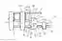
FIG. 2 shows in cross section the pair of rails 3 comprising the lower rail 5, the upper rail 7 and the bearing element 9.
The lower rail 5 comprises, for example, four ball cages which are configured as bearing elements 9 or else are referred to as moving cages, by means of which the upper rail 7 is mounted in a longitudinally displaceable manner on four raceways or supports. Alternatively, other suitable forms or elements can also be used as the bearing elements 9.
The lower rail 5 and the upper rail 7 engage around each other here with their substantially U shaped profiles at longitudinal ends 5.1, 7.1 which are bent inward or outward.
A stop 11 for a pin guiding plate 17 is positioned in the lower rail 5 and is held and fixed on the latter by means of a fixing element 13. The fixing element 13 can optionally be provided here. The stop 11 is configured such that said stop itself is positionable variably on the lower rail 5 and is automatically fixable on the latter.
For this purpose, the stop 11 comprises a stop element 15.
FIG. 3 shows in longitudinal section the pair of rails 3 with the stop 11 positioned in the lower rail 5 and the stop element 15 in detail. The stop element 15 is configured such that it is positionable variably on the lower rail 5 and is automatically fixable.
For this purpose, the stop element 15 has at least two protruding holding elements 15.1, 15.2, of which one is angled in a hook shaped manner and the other is of pin shaped design.
By this means, the stop element 15 is positionable and fixable in the lower rail 5 by means of a positioning and fixing connection, in particular is pluggable in said rail in an automatically fixing manner.
For the optional or additional fixing of the automatically fixable plug in connection of the stop 11, in particular the pin shaped holding element 15.2 thereof, the flexible fixing element 13 is provided. The flexible fixing element 13 is configured, for example, as a holding spring. The holding spring is, for example, an omega spring.
In one possible embodiment, the pin shaped holding element 15.2 can be is configured such that the latter fixes itself with a form fit and/or force fit connection. For this purpose, the pin shaped holding element 15.2 is formed, for example, from a flexible material or is of flexible and profiled design at least on an outer side, and therefore a plug in and clamping connection of the stop 11 on the pair of rails 3, in particular on the lower rail 5, is made possible.
In other words: the variably positionable stop 11 is variably positionable and automatically fixable as an additional geometrical component or a flexible end stop in one of the rails 5 or 7 of the pair of rails 3. The stop 11 can fix itself here or can be held and fixed on the pair of rails 3 by additional connecting means, such as the flexible fixing element 13.
The flexible fixing element 13, for example a clamping spring, is pluggable onto the stop 11 vertically from above or from below in the region of the pin shaped holding element 15.2 and is fixable, in particular clampable, to the lower rail 5.
By this means, it is possible on existing rail profiles with fixed rail stop ends to limit the existing travel distance by retrospective positioning and fixing of the stop 11 according to the invention. The stop 11 here can shorten the travel distance forward or rearward by corresponding variable positioning on one of the rails 5 or 7.
The stop 11 is moreover formed, at least in the stop region 15.3, of a solid material, in particular of metal. In the region of the plug in connection, the stop can be formed from a flexible material. The stop 11 is designed and shaped such that, in the event of the incursion of a load, for example by means of a pin guiding plate 17, the stop region 15.3 can be used as an end stopper and therefore as shortening of the travel distance.
The stop region 15.3 has a stop surface 15.4. Furthermore, the stop surface 15.4 can be of profiled design on the end side, and therefore vertical contact surfaces V and horizontal contact surfaces H are formed. For example, the stop surface 15.4 has webs 20 protruding therefrom. The webs 20 can be formed here in differing lengths in order additionally to form a plug in connection. The webs 20 can also be provided with a contour or bevel in order, for example, to assist a positioning, in particular plugging in, of the stop 11 and/or in order to improve an introduction of force in the event of the incursion of a load.
In particular, the stop surface 15.4 corresponds with an end contact surface 17.1 of the pin guiding plate 17. By this means, the forces which occur over the entire end contact surface 17.1 of the pin guiding plate 17 are distributed to the stop surface 15.4. In the event of the incursion of a load onto the stop surface 15.4 by means of the pin guiding plate 17, a torque D arises, initiated at contact points S1 by the profiling of the end contact surface 17.1 of the pin guiding plate 17.
FIG. 4 shows the stop 11 in top view. The stop 11 here has increased dimensions away from the end side stop surface 15.4.
The stop 11 absorbs the torque D, which acts in the event of the incursion of a load, in the lower rail 5 by means of the front holding element 15.1, for example a front hook, and a rear large receiving surface 15.5 and acts as an end stop and permits an improved introduction of force.
In addition, as shown in FIG. 3, in the event of a load when the torque D occurs, a pin 17.2 of the pin guiding plate 17 acts directly on a further contact point S2 in the lower rail 5. Therefore, in the event of a load, the torque D entering via the lower rail 5 at at least one further contact point S2 additionally acts on the stop 11 at the contact point S3 and therefore supports the vertical stop surface 15.4 in the region of the contact point S1.
The torque D additionally acts in the region of the two holding elements 15.1, 15.2 which are held on the lower rail 5 with a form fit connection and are positioned and held in fixing openings 19, for example punched holes, in the lower rail 5 in order, in the event of a load, to serve for absorbing the load.
Furthermore, the stop 11, in particular the stop region 15.3, has an increasing height in the direction of the end side stop surface 15.4.
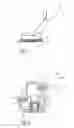
FIG. 5 shows schematically in cross section a further exemplary embodiment of a pair of rails 3 with a stop 11 positioned in a lower rail 5.
FIG. 6 shows schematically in longitudinal section the pair of rails 3 according to FIG. 5. The stop 11 here is configured such that it is positionable and automatically fixable variably at a holding position. The stop 11 is preferably insertable variably at a holding position in the interior of the pair of rails 3. For example, the stop 11 is positioned and automatically fixed on the lower rail 5.
The webs 20 are provided with a rising contour, in particular a rising slope, in order to assist with a positioning, in particular plugging in, of the stop 11 in the pair of rails 3 and to improve an introduction of force in the event of the incursion of a load.
The stop surface 15.4 corresponds here with an end contact surface 17.1 of the pin guiding plate 17. By this means, the forces occurring over the entire end contact surface 17.1 of the pin guiding plate 17 are distributed to the stop surface 15.4. In the event of the incursion of a load on the stop surface 15.4 by means of the pin guiding plate 17, a torque D arises, initiated at contact points S1 by the profiling of the end contact surface 17.1 of the pin guiding plate 17.
Furthermore, the stop 11 has dimensions which are increased away from the end side stop surface 15.4.
The stop 11 absorbs the torque D, which acts in the event of the incursion of a load, in the lower rail 5 by means of the front holding element 15.1, for example a front hook, and a rear large receiving surface 15.5 and acts as an end stop and permits an improved introduction of force.
In addition, in the event of a load when the torque D occurs, the pin 17.2 of the pin guiding plate 17 acts directly in the lower rail 5, and therefore, in the event of a load, the torque D entering via the lower rail 5 additionally acts on the stop 11.
FIG. 7 shows the pair of rails 3 in a top view with the upper rail 7 partially cut open in order to illustrate the stop 11 fixed in the lower rail 5. The stop 11 is additionally fastened releasably here to the pair of rails 3 by means of the separate fixing element 13.
FIG. 8 shows the pair of rails 3 in a perspective illustration, wherein the stop 11 is additionally fastened releasably to the pair of rails 3 by means of a fixing element 13 configured as an omega spring.
FIGS. 9 to 12 schematically show various illustrations of an exemplary embodiment of the stop 11 with a separate fixing element 13. The stop 11 here has a receptacle 15.6 into which the fixing element 13 is pluggable and is holdable with a form fit or force fit connection. The receptacle 15.6 comprises two recesses 15.7 in which spring arms 13.1 of the fixing element 13 are guided and held. The free ends 13.2 of the spring arms 13.1 are angled outward, and therefore said ends 13.2 in the fitted state engage in a latching manner on the pair of rails 3.
The fixing element 13 is configured such that said fixing element holds the stop element 15 in a reversibly releasable manner on the pair of rails 3.
The front holding element 15.1 of the stop element 15 is of hook shaped design and comprises a hook 15.8 protruding forward from the stop surface 15.4. By means of the hook 15.8, the stop element 15 can be pre positioned and held with a form fit and/or force fit connection on the pair of rails 3.
Depending on the arrangement of the stop 11 on the pair of rails 3, and depending on the forces acting on said holding position when one of the rails 5, 7 strikes against the stop 11 during a longitudinal adjustment, the additional fixing element 13 can be omitted or provided. For example, the fixing element 13 can be omitted in the case of a stop 11 which is provided as a front end stop. By contrast, in the case of a stop 11 provided as a rear end stop, said stop is additionally held on the pair of rails 3, in particular on the lower rail 5, by means of the fixing element 13.
FIG. 10A shows the stop 11 with the fixing element 13, which is arranged in the receptacle 15.6, in a sectional illustration. In this embodiment, the fixing element 13 is configured as an omega spring. For example, the fixing element 13 can be a metal spring and can be of U shaped design with lateral spring arms 13.1.
FIG. 10B shows, in the section XB, the stop 11 with the stop element 15 and the lateral spring arms 13.1 of the fixing element.
FIG. 11 shows the stop 11 in a view from below with the stop element 15 and the forwardly protruding hook 15.8 for positioning and fastening the stop 11 itself and with the further pin shaped holding element 15.2 of the stop 11 and the free ends 13.2 of the additional fixing element 13, said free ends protruding laterally from the holding element, for the additional fastening of the stop 11 to the pair of rails 3, in particular to the lower rail 5.
FIG. 12 shows the stop 11 in a top view from above with the additional fixing element 13 which is arranged in the receptacle 15.6, wherein the spring arms 13.1 are guided and held in the recesses 15.7.
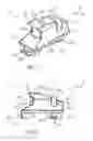
FIGS. 13 to 18 show schematically different illustrations of an alternative exemplary embodiment of a stop 11′ with a separate fixing element 13′.
In the alternative embodiment, the fixing element 13′ is configured as a plug in element 21 which is arrangeable in the stop element 15′ with a form fit and/or force fit connection.
In this simple embodiment, the fixing element 13′ can be a plastics part, in particular an injection molded part. For example, the fixing element 13′ can be formed from a thermoplastic elastomer, in particular polypropylene or polyethylene. The stop element 15′ and the fixing element 13′ can be formed here from the same plastics material. Alternatively, the stop element 15′ can be formed from a firmer plastics material than the fixing element 13′.
Furthermore, the fixing element 13′ is arrangeable irreversibly on or in the stop element 15′. For this purpose, the stop element 15′ has, for example, a receptacle 15.6′. The receptacle 15.6′ is configured as a recess 15.7′, the contour of which corresponds with the contour of the fixing element 13′. For example, the fixing element 13′ is configured as a plug in element 21 with a web 21.1 protruding therefrom, in particular a T shaped web 21.1. Corresponding to said T shaped web 21.1, the receptacle 15.6′ has a correspondingly T shaped recess 15.7′.
The fixing element 13′ is configured such that said fixing element is arrangeable irreversibly in the stop element 15′, in particular in the recess 15.7′.
FIG. 15 shows the insertion of the alternative stop 11′ into a pair of rails 3′, in particular into the lower rail 5′. First of all here the stop element 15′, as shown in a position I, is pluggable with the rear holding element 15.2′ into an opening 19′ of the lower rail 5′. The holding element 15.2′ has a protruding hook 15.8′ which engages under the lower rail 5′ after displacement from an intermediate position II in the longitudinal direction R into a holding position III.
The holding element 15.1′ also has a protruding hook 15.8′ which, in the displaced end state in the holding position III of the stop 11′, holds said stop 11′ on the lower rail 5′.
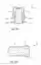
FIG. 16 shows the stop 11′ in the holding position III.
When the stop 11′ is used, for example, as an end stop, the stop 11′ can additionally be provided with a fixing element 13′.
The fixing element 13′ in the present case is a plug in element 21 which, after the stop 11′ is held in the holding position III on the lower rail 5′, is plugged from above into the stop 11′, in particular into the receptacle 15.6′ thereof. The plug in element 21 is arranged and held here both in the receptacle 15.6′ and in the opening 19′ of the lower rail 5′ with a form fit and/or force fit connection.
The fixing element 13′ is configured such that it is held irreversibly in the receptacle 15.6′ and in the opening 19′. For example, the fixing element 13′ for this purpose has at least one depression 13.3 and the stop element 15′ correspondingly has at least one protrusion 15.9, or vice versa.
In particular, the fixing element 13′ has, on the outer side, in particular on the end side, in particular a notch, score or groove as the depression 13.3. The stop element 15′, in particular the recess 15.7′ of the stop element 15′, correspondingly has the at least one protrusion 15.9, for example a rib, a web or a saw tooth rib. Alternatively, the fixing element 13′ can have a protrusion and the stop element 15′ can correspondingly have a depression.
The fixing element 13′ can be is configured such that said fixing element is both arrangeable irreversibly in the stop element 15′ and also automatically and irreversibly fixes the stop element 15′ in the holding position III. By means of such a fixing element 13′ which is held irreversibly in the stop element 15′ and holds the stop element 15′ automatically and irreversibly in the holding position III, a simple stop which can be variably positioned and fixed is provided.
FIG. 17 shows the stop 11′ in the holding position III with the fixing element 13′ inserted and irreversibly fastened. The stop element 15′ engages here around the lower rail 5′ in a U shaped manner. For this purpose, the stop element 15′ has the protruding hooks 15.8′ on the holding elements 15.1′, 15.2′. By means of additional cutouts 15.10 in the holding elements 15.1′, 15.2′, the stop element 15′ engages around the lower rail 5′ in the openings 19′ in a U shaped manner.
FIG. 18 shows the stop 11′ as a front end stop which is inserted and fixed in one of the openings 19′. By means of an actuating lever 22, a seat 23 can be stopped at the stop 11′ on being moved forward in the longitudinal direction R.
While specific embodiments of the invention have been shown and described in detail to illustrate the application of the principles of the invention, it will be understood that the invention may be embodied otherwise without departing from such principles.
Claims
1. An end stop for a longitudinal adjustment device, the end stop comprising:
a stop element which is variably positionable and is configured to be automatically fixed in a holding position.
2. The end stop as claimed in claim 1, wherein the stop element is configured as a combined positioning and fixing element.
3. The end stop as claimed in claim 1, wherein the stop element has at least two protruding holding elements, of which one of the at least two protruding holding elements is angled with a hook shape and the other of the at least two protruding holding elements is of a pin shaped configuration.
4. The end stop as claimed in claim 3, wherein at least one of the holding elements is a flexible holding element with a flexible configuration such that a plug in and clamping connection is made possible.
5. The end stop as claimed in claim 4, wherein the flexible holding element is formed from a flexible material.
6. The end stop as claimed in claim 4, wherein the flexible holding element is of flexible configuration at least on an outer side.
7. The end stop as claimed in claim 3, wherein at least one of the holding elements is of profiled configuration on the an outer side.
8. The end stop as claimed in claim 1, further comprising a fixing element arrangeable with a form fit connection or a force fit connection or both a force fit and a form fit connection on the stop element.
9. The end stop as claimed in claim 8, wherein the fixing element is configured as a holding spring.
10. The end stop as claimed in claim 8, wherein the fixing element is configured as a plug in element arrangeable with a form fit connection or a force fit connection or both a force fit and a form fit connection in the stop element.
11. The end stop as claimed in claim 8, wherein the fixing element is irreversibly arrangeable in a receptacle of the stop element.
12. The end stop as claimed in claim 8, wherein the fixing element has at least one depression and the stop element correspondingly has at least one protrusion, or the stop element has at least one depression and the fixing element correspondingly has at least one protrusion.
13. A longitudinally adjustable rail arrangement comprising:
a pair of rails;
an end stop comprising a stop element which is variably positionable and is configured to be automatically fixed in a holding position.
14. The longitudinally adjustable rail arrangement as claimed in claim 13, wherein the stop is arrangeable in a positionable and automatically fixable manner on a rail of the pair of rails.
15. The longitudinally adjustable rail arrangement as claimed in claim 14, wherein the stop is releasably arrangeable in an interior space between the rails of the pair of rails.
16. The longitudinally adjustable rail arrangement as claimed in claim 15, wherein the stop element comprises a combined positioning and fixing element.
17. The longitudinally adjustable rail arrangement as claimed in claim 15, wherein the stop element comprises two protruding holding elements with one of the two protruding holding elements angled with a hook shape and another of the two protruding holding elements having a pin shape and at least one of the holding elements comprises a flexible holding element formed of a flexible material.
18. The longitudinally adjustable rail arrangement as claimed in claim 15, further comprising a fixing element arrangeable, with a form fit connection or a force fit connection or both a force fit and a form fit connection, on the stop element.
19. The longitudinally adjustable rail arrangement as claimed in claim 18, wherein:
the fixing element is configured as a omega shaped holding spring;
the fixing element is configured as a plug in element arrangeable, with the form fit connection or the force fit connection or both the force fit and the form fit connection, in the stop element.
20. The longitudinally adjustable rail arrangement as claimed in claim 18, wherein:
the fixing element comprises at least one depression and the stop element correspondingly has at least one protrusion; or
the stop element has at least one depression and the fixing element correspondingly has at least one protrusion.
Images & Drawings included:


Sources:
- United States Patent and Trademark Office - verify current appl. status at the USPTO↗
Recent applications in this class:
- » 20250196728 2025-06-19
LONGITUDINAL SEAT-ADJUSTMENT DEVICE AND VEHICLE SEAT - » 20250187500 2025-06-12
SEAT TRACK MECHANISM WITH ADJUSTABLE SPACER LENGTH - » 20250170925 2025-05-29
SEAT SLIDER - » 20250121742 2025-04-17
STOPPER ASSEMBLY FOR A SEAT TRACK ASSEMBLY - » 20240416802 2024-12-19
Stopper assembly for a seat track assembly - » 20230256870 2023-08-17
SLIDING RAIL HAVING ENHANCED RIGIDITY MODULUS - » 20230211708 2023-07-06
Seat slide device - » 20220281359 2022-09-08
Seat slide adjuster - » 20220185150 2022-06-16
Longitudinal adjusting device for the motorized longitudinal adjustment of a vehicle seat, and vehicle seat - » 20220118887 2022-04-21
Memory module and seat mounting structure with easy entry module
Recent applications for this Assignee:
- » 20240229906 2024-07-11
ELECTRIC CABLE DRIVING MECHANISM HAVING SELF-RETURN FUNCTION - » 20240133453 2024-04-25
ELECTRIC CABLE DRIVING MECHANISM HAVING SELF-RETURN FUNCTION - » 20220402407 2022-12-22
Fitting for a vehicle seat - » 20220281363 2022-09-08
Double fitting for a vehicle seat, and vehicle seat - » 20220266725 2022-08-25
Welcoming slide rail - » 20220227260 2022-07-21
Longitudinal adjuster and vehicle seat - » 20220219578 2022-07-14
Adjustment fitting for a vehicle seat and vehicle seat - » 20220219577 2022-07-14
Fitting for vehicle seat - » 20220212574 2022-07-07
Adjustment fitting for a vehicle seat - » 20220161692 2022-05-26
Longitudinal adjustment mechanism, vehicle seat