MULTIPLE-ORIFICE JEWEL FOR FLUID-JET DEVICE
US20180236635A1
2018-08-23
15/435,646
2017-02-17
Abstract:
Systems, apparatuses, and methods for generating a fluid-jet stream through a multiple-orifice jewel so that abrasive particulates can more evenly distributed in the resultant fluid-abrasive stream. In an embodiment, a fluid-jet cutting device may include a fluid inlet configured to receive fluid from a fluid supply; which is coupled to a jewel having multiple orifices by which fluid may be pumped through to generate several separated fluid-jet streams. An abrasive inlet disposed adjacent to the first jewel surface may be configured to inject an abrasive into the vacuum created between a plurality of fluid-jet streams exiting the plurality of orifices of the jewel prior to a convergence point where the plurality of fluid-jet streams converge with each other and with the abrasive. In this manner, instead of remaining at the outskirts of the single fluid-jet stream as is the case with conventional fluid-jet cutting devices, the abrasive is more fully immersed in the converged fluid-jet stream.
Inventors:
- Ted E. Jernigan 1 🇺🇸 Olympia, WA, United States
- Perry M. Hanchey 1 🇺🇸 Olympia, WA, United States
- Adam R. Miranda 1 🇺🇸 Olympia, WA, United States
Interested in similar patents?
Get notified when new applications in this technology area are published.
Classification:
B24C1/045 » CPC further
Methods for use of abrasive blasting for producing particular effects; Use of auxiliary equipment in connection with such methods for treating only selected parts of a surface, e.g. for carving stone or glass for cutting
B24C5/04 » CPC main
Devices or accessories for generating abrasive blasts; Blast guns, e.g. for generating high velocity abrasive fluid jets for cutting materials Nozzles therefor
B24C1/04 IPC
Methods for use of abrasive blasting for producing particular effects; Use of auxiliary equipment in connection with such methods for treating only selected parts of a surface, e.g. for carving stone or glass
Description
BACKGROUND
Fluid-jet cutting machines (sometimes called water-jet cutting machines, but referred to as fluid-jets throughout this disclosure) are used in industry to cut a variety of materials using a highly-pressurized stream of fluid precisely positioned to strike an object to be cut. Further, many fluid-jets may use an abrasive substance that when added to the fluid-jet stream provides greater cutting capability. A typical fluid-jet device may include a fluid inlet for receiving a supply of fluid (e.g., water) that feeds a jewel orifice (typically just called a jewel) wherein water is pumped through a small orifice in the jewel in an effort to produce a water-jet stream of high pressure resulting in high velocity. Upon exiting the jewel orifice, an additional substance may be fed into the fluid-jet stream in a mixing tube just beyond the exit point of the jewel orifice. Together, the components form a cutting head assembly configured to direct the fluid-jet stream of fluid-abrasive mixture onto an object to be cut.
However, a particular problem that exists when introducing an abrasive to the high-velocity fluid-jet stream is that the individual particulates in the abrasive substance tend to remain on the outer portions of the fluid-jet stream and tend to remain only within the side in which the abrasive is first introduced. This results in fluid-jet stream of fluid-abrasive mixture that is unbalanced and favoring one portion of a cross-section of the final fluid-jet stream. As a result, conventional ways of inserting an abrasive into a fluid-jet stream lead to inequities in cutting precision (e.g., one side (with more abrasive particulate) of the fluid-jet stream cuts a bit better than the other side (with fewer or no abrasive particulates).
BRIEF DESCRIPTION OF THE DRAWINGS
Embodiments of the subject matter disclosed herein in accordance with the present disclosure will be described with reference to the drawings, in which:
FIG. 1 is a diagram illustrating a device for generating a fluid-jet stream using any orifice jewel according to an embodiment of the subject matter disclosed herein;
FIG. 2 is a diagram illustrating a side view of a multiple-orifice jewel for use in a device for generating a fluid-jet stream according to an embodiment of the subject matter disclosed herein;
FIG. 3 is a diagram illustrating a top view of a multiple-orifice jewel for use in a device for generating a fluid-jet stream according to an embodiment of the subject matter disclosed herein;
FIG. 4 is a diagram illustrating a device for generating a fluid-jet stream using a multiple-orifice jewel according to an embodiment of the subject matter disclosed herein; and
FIG. 5 is a diagram illustrating a system having the device of FIG. 4 according to an embodiment of the subject matter disclosed herein.
Note that the same numbers are used throughout the disclosure and figures to reference like components and features.
DETAILED DESCRIPTION
The subject matter of embodiments disclosed herein is described here with specificity to meet statutory requirements, but this description is not necessarily intended to limit the scope of the claims. The claimed subject matter may be embodied in other ways, may include different elements or steps, and may be used in conjunction with other existing or future technologies. This description should not be interpreted as implying any particular order or arrangement among or between various steps or elements except when the order of individual steps or arrangement of elements is explicitly described.
Embodiments will be described more fully hereinafter with reference to the accompanying drawings, which form a part hereof, and which show, by way of illustration, exemplary embodiments by which the systems and methods described herein may be practiced. This systems and methods may, however, be embodied in many different forms and should not be construed as limited to the embodiments set forth herein; rather, these embodiments are provided so that this disclosure will satisfy the statutory requirements and convey the scope of the subject matter to those skilled in the art.
By way of overview, various embodiments as discussed herein are directed to systems, apparatuses, and methods for generating a fluid-jet stream through a multiple-orifice jewel so that abrasive particulates can more evenly distributed in the resultant fluid-abrasive stream, in an embodiment, a fluid-jet cutting device may include a fluid inlet configured to receive fluid from a fluid supply; which is coupled to a jewel having multiple orifices by which fluid may be pumped through to generate several separated fluid-jet streams. Such a multiple orifice jewel may be characterized as having a first jewel surface having a substantially flat surface disposed in a first plane, a plurality of additional jewel surfaces, each additional jewel surface having a substantially flat surface disposed in a plane other than the first plane; and a plurality of orifices disposed through the jewel such that each orifice extends from the first jewel surface to one of the plurality of additional jewel surfaces. Thus, each orifice, which may be angled in such a way as to point each formed jet stream toward a convergence point below the bottom surface of the jewel, then creates a vacuum in a space between each newly created jet stream.
With a vacuum created, an injector or abrasive inlet disposed adjacent to the first jewel surface may be configured to inject an abrasive (e.g., metal particulates) into the vacuum created between a plurality of fluid-jet streams exiting the plurality of orifices of the jewel prior to a convergence point where the plurality of fluid-jet streams converge with each other and with the abrasive. In this manner, instead of remaining at the outskirts of the single fluid-jet stream as is the case with conventional fluid-jet cutting devices, the abrasive is more fully immersed in the converged fluid-jet stream because the abrasive tends to enter the stream at the center areas of the converged stream. These aspects as well as additional advantages and benefits will become more apparent when understood with respect to the descriptions below in conjunction with FIGS. 1-5.
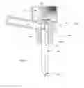
FIG. 1 is a diagram illustrating a fluid-jet device 100 for generating a fluid-jet stream using any orifice jewel according to an embodiment of the subject matter disclosed herein. Fluid-jet (sometimes called water-jet) is a generic term used to describe equipment that generates a high-pressure stream of fluid for cutting or cleaning purposes. Fluid-jets may further include a means for introducing an abrasive to the fluid-jet stream and may generally be called an abrasive-jet. Abrasive-jet is a subcategory of fluid-jet in which abrasive is introduced to accelerate the cutting or cleaning process. Pure fluid-jet and fluid-only cutting can be specifically distinguished from abrasive-jets that use abrasive. However, as is common in many industries, the term fluid-jet has become short-hand for referring to both fluid(only)-jets and abrasive-jets. In this disclosure, the term fluid-jet will refer to topics that cover both pure fluid-jet devices and abrasive-jet devices as the context will make clear what is being referred to in each embodiment,
As shown in FIG. 1, a fluid-jet cutting device 100 includes a fluid inlet 110 that may be configured to be coupled to a fluid supply (not shown). In this manner, fluid may be pumped to the fluid-jet device by a fluid pump (not shown) as controlled by a control system (not shown). The fluid pumped into the fluid inlet 110 is then forced through a jewel orifice 120 (called jewel 120 hereinafter) where the velocity of the fluid exiting the jewel 120 is extreme. Typically, the pump will create pressures from 30,000 psi to 90,000 psi and the velocity of the fluid exiting the jewel 120 will be approximately 600 miles per hour (e.g., super-sonic speeds).
The jewel 120 may be held in place by a jewel mount 121 that allows for each orifice in the jewel 120 to be exposed to a mixing tube 160 disposed beyond the exit points of the one or more orifices of the jewel 120. Further, the jewel 120, jewel mount 121, mixing tube 160, and abrasive feed tube 140 may be secured in place and configured for use by a jewel housing 150. The mixing tube extends beyond the bottom boundary of the jewel housing which then forms a nozzle end 161. In this manner, one or more fluid-jet streams 125 may be formed by the jewel 120 and mixed with abrasive in the mixing tube 160 prior to exiting the nozzle end 161 as a fluid-abrasive jet stream 130, As will be discussed in greater detail with respect to FIG. 4, the multiple fluid streams 125 may converge at a convergence point 126 after abrasive is injected at an abrasive injection point 141.
The jewel 120, as shown in FIG. 1 may have multiple orifices (sometimes called bores) through the jewel 120 that allow for fluid to pass from the fluid inlet 110 to the mixing tube 160. In an embodiment discussed throughout this disclosure, the jewel 120 includes four orifices that are positioned equidistant from each other in the jewel 120,
Further, as is shown with respect to the FIGS. 2-4 below, each orifice may be disposed at an angle such that a respective fluid stream that is produced may be aimed at the convergence point 126 at some distance beyond the bottom surface of the jewel, Having multiple fluid streams exiting the jewel may create an interior space between the fluid streams prior to convergence. Because of the high velocity of the fluid streams, this interior space forms a vacuum. Thus, abrasive may be fed into this vacuum in this interior space. Then, as the fluid streams converge, the abrasive joins the resultant fluid-abrasive-jet stream from within the vacuum. This is an improvement over a single orifice jewel producing a single fluid stream where the abrasive does not typically mix evenly with the fluid-abrasive-jet stream. Rather, the conventional fluid-jet exhibits a fluid-abrasive streams with abrasive only disposed at the periphery of the fluid-abrasive-jet stream. Specific aspects of one embodiments of a multiple orifice jewel 120 are discussed next with respect to FIGS. 2 and 3.
FIG. 2 is a diagram illustrating a side view of a multiple-orifice jewel 120 for use in a device for generating a fluid-jet stream according to an embodiment of the subject matter disclosed herein. In this embodiment, the jewel 120 may include four different orifices, although only two (first orifice 250 and second orifice 251) of the orifices can be seen clearly in the side view of FIG. 2. The jewel 120 includes a bottom jewel surface 257 having a substantially flat surface disposed in a bottom plane 201. A skilled artisan understands that the use of terms like “bottom” are relative to the drawings that are used for ease of illustration and that the jewel may be oriented in any manner such that the term bottom and other similar terms are always relative. Further, the jewel 120 includes a plurality of additional jewel surfaces wherein each additional jewel surface also exhibits a substantially flat surface. Each of the additional jewel surfaces may be disposed in a respective plane other than the bottom plane 201. As can be seen in FIG. 2, a first additional surface 260 may be disposed in a first additional plane 202 and a second additional surface 261 may be disposed in a second additional plane 203. Although not shown in FIG. 2, the jewel 120 may include a third and fourth additional surface disposed in respective third and fourth planes. Of the first through fourth additional planes, none of the planes are congruent with any other plane including the bottom plane 201. Lastly, the jewel 120 may include a side surface 255 that is curved and provides side boundaries of the jewel. The side surface is contiguous with the bottom surface 257 and each additional surface.
The jewel 120 further includes, in this embodiment, four orifices respectively extending from the bottom surface 257 to a respective additional surface. Thus, as can be seen in FIG. 2, the first orifice 250 is shown extending from the bottom surface 257 to the first additional surface 260. Likewise, the second orifice 251 is shown extending from the bottom surface 257 to the second additional surface 261. Although not shown in FIG. 2, third and fourth orifices extend from the bottom surface to respective third and fourth additional surfaces. Further, each of the orifices (first through fourth) are disposed at an angle with respect to the bottom plane 257. Different from a conventional jewel which exhibits one orifice disposed at an angle normal to the bottom plane 201, the jewel 120 of FIG. 2 has multiple orifices each offset from the normal of the bottom plane 201. To this end, each orifice is disposed at an angle configured to intersect a convergence point (not shown in FIG. 2) beyond the bottom surface 257 of the jewel 120. Thus, the first orifice 250 is disposed at an angle congruent with axis 204. Likewise, the second orifice 251 is disposed congruent with the axis 205. In one embodiment, the angle is approximately 10-20 degrees (but vary from 5-90 degrees) from the normal of the bottom surface 257 and is normal to the respective additional surface. The location of the orifices may vary from close to the edge of the jewel to close to the center of the jewel. Further, the size of each orifice may vary widely depending on desired stream size.
The jewel 120 may typically comprise a diamond substance, but may also be made from other super hard materials and minerals with Mohs hardness ratings of, or in excess of 9, such as PCD, CBN, corundum, and carbide, all of which may be less robust that diamond substance for applications that may not call for the highest pressure and highest velocity cutting streams. Further, although the above-described embodiment includes four additional surfaces with four orifices, a skilled artisan understands that any plurality of orifice-surface combinations may be realized in a multiple orifice jewel 120. Further, different embodiments may include additional surface that do not have a respective orifice bored therethrough. Further yet, other different embodiments may include one or more additional surfaces that more than one respective orifice bored therethrough.
FIG. 3 is a diagram illustrating a top view of a multiple-orifice jewel 120 for use in a device for generating a fluid-jet stream according to an embodiment of the subject matter disclosed herein. In this top view, each orifice as discussed with respect to FIG. 2 is more easily distinguished. Thus, the first orifice 250 is shown extending to the first additional surface 260, the second orifice 251 is shown extending to the second additional surface 261, the third orifice 252 is shown extending to the third additional surface 262, and the fourth orifice 253 is shown extending to the fourth additional surface 263. As can more easily be distinguished in FIG. 3, the jewel 120 may comprise quadrants wherein each quadrant is a separately crafted portion that can be combined with other similarly crafted portions, In other embodiments, the number of partitions may be different or may be differently shaped. For example, other embodiments not shown may have between two and five partitions that may or may not be equally partitioned.
FIG. 4 is a diagram illustrating a device 100 for generating a fluid-jet stream using a multiple-orifice jewel 120 according to an embodiment of the subject matter disclosed herein. FIG. 4 shows a zoomed-in view of the device 100 from FIG. 1 so as to more clearly show the manner in which abrasive is introduced to a vacuum created between multiple fluid-jet streams. Thus, a multiple-orifice jewel may create more than one fluid-jet stream when a fluid (e.g., water) is forced through the small orifices of the jewel. Each orifice in the jewel 120 may typically be 0,001″ to 0.030″ in diameter (0.025 to 0.762 mm). which creates a very high-velocity, thin beam of fluid. In this embodiment, three such fluid-jet streams are shown, a first fluid-jet stream 125a, a first fluid-jet stream 125b, and a third fluid-jet stream 125c. A fourth fluid-jet stream may be present when used with the jewel 120 of FIGS. 2 and 3, but is not easily illustrated in the view of FIG. 4. The combination of high-velocity fluid-jet streams 125a, 125b, and 125c exiting the jewel 120 creates a vacuum in an interior space between the streams within the mixing tube 160.
As discussed previously, an abrasive inlet 140 may be disposed with respect to the mixing tube so that an injection point 141 is within the vacuum created in the interior space between streams. This vacuum pulls abrasive from the abrasive inlet 140, which then mixes with the fluid streams in the mixing tube 160 beyond the injection point 141 as each of the streams converge at the convergence point 126. The converging streams of fluid accelerate abrasive particles to speeds fast enough to cut through very hard materials. The fluid-jet streams exiting the jewel converge at the convergence point 126 because the fluid-jet streams are generated at an angle through respective orifices in the jewel 120 having an axis of propagation that intersects beyond the abrasive injection point 141, The injected abrasive may be garnet, aluminum oxide, olivine, and the like depending on that which is being cut. The cutting action of a fluid-abrasive-jet stream is two-fold, The force of the fluid and abrasive erodes the material to be cut, even if the fluid-jet nozzle is stationary (which is how the material may be initially pierced). The cutting action may be greatly enhanced if the fluid-abrasive-jet stream is moved across the material wherein the ideal speed of movement may depend on a variety of factors, including the material being cut, the shape of the object being cut, the fluid pressure, and the type of abrasive, Controlling the speed of the fluid-jet nozzle is a factor in efficient and economical machining.
FIG. 5 is a diagram illustrating a system 500 having the device of FIG. 4 according to an embodiment of the subject matter disclosed herein. In this system 500, a fluid-jet cutting device assembly 100 may be attached to an actuator 583 that is maneuverable within a carriage or gantry or other means for imparting motion to the fluid-jet device assembly 100. Further, a fluid pump 581 may pump a fluid, such as water from a fluid supply 582 to the fluid inlet of the fluid-jet assembly 100. Further yet, an abrasive feeder 586 may supply abrasive from an abrasive supply 585 to the abrasive inlet of the fluid-jet assembly 100. Collectively, the fluid pump 581, the abrasive feeder 586, and the actuator 583 may be communicatively coupled to and controlled by a controller 580 so as to cut a target object 590.
In one embodiment, the controller may be configured to adjust the injection of abrasive into the vacuum to change the amount of abrasive in the converged fluid-abrasive stream. In another embodiment, the controller may be configured to adjust the pumping of fluid into the jewel to change the velocity of the converged fluid-abrasive stream. Because fluid-jets cut using fluid and abrasive, the fluid-jet 100 is operable to function to cut, shape, form, or otherwise modify a wide variety of materials. These materials include copper, brass, aluminum, pre-hardened steel, mild steel, titanium, Inconel, hastalloy, glass (non-tempered), ceramic, quartz, stone, laminated materials, and flammable materials. With fluid-jet machining, a flat piece of material may be placed on a table so that a fluid-jet cutting head can move across the material (although in some custom systems, the material moves past a fixed head). The movement of the fluid-jet cutting head is controlled by controller 580, which greatly simplifies control of the fluid-jet. In some embodiments, “programming” the cutting of an object may include using a Computer-Aided Design (CAD) drawing to model the object so that an operator need only initiate the process.
It should be understood that the present disclosures as described above can be implemented in the form of control logic using computer software in a modular or integrated manner. Based on the disclosure and teachings provided herein, a person of ordinary skill in the art will know and appreciate other ways and/or methods to implement the present disclosure using hardware and a combination of hardware and software.
Any of the software components, processes or functions described in this application may be implemented as software code to be executed by a processor using any suitable computer language such as, for example, Java, Javascript, C++ or Perl using, for example, conventional or object-oriented techniques. The software code may be stored as a series of instructions, or commands on a computer readable medium, such as a random access memory (RAM), a read only memory (ROM), a magnetic medium such as a hard-drive or a floppy disk, or an optical medium such as a CD-ROM. Any such computer readable medium may reside on or within a single computational apparatus, and may be present on or within different computational apparatuses within a system or network.
All references, including publications, patent applications, and patents, cited herein are hereby incorporated by reference to the same extent as if each reference were individually and specifically indicated to be incorporated by reference and/or were set forth in its entirety herein.
The use of the terms “a” and “an” and “the” and similar referents in the specification and in the following claims are to be construed to cover both the singular and the plural, unless otherwise indicated herein or clearly contradicted by context. The terms “having,” “including,” “containing” and similar referents in the specification and in the following claims are to be construed as open-ended terms (e.g., meaning “including, but not limited to,”) unless otherwise noted. Recitation of ranges of values herein are merely indented to serve as a shorthand method of referring individually to each separate value inclusively falling within the range, unless otherwise indicated herein, and each separate value is incorporated into the specification as if it were individually recited herein. All methods described herein can be performed in any suitable order unless otherwise indicated herein or clearly contradicted by context. The use of any and all examples, or exemplary language (e.g., “such as”) provided herein, is intended merely to better illuminate embodiments and does not pose a limitation to the scope of the disclosure unless otherwise claimed. No language in the specification should be construed as indicating any non-claimed element as essential to each embodiment of the present disclosure.
Different arrangements of the components depicted in the drawings or described above, as well as components and steps not shown or described are possible. Similarly, some features and sub-combinations are useful and may be employed without reference to other features and sub-combinations. Embodiments have been described for illustrative and not restrictive purposes, and alternative embodiments will become apparent to readers of this patent. Accordingly, the present subject matter is not limited to the embodiments described above or depicted in the drawings, and various embodiments and modifications can be made without departing from the scope of the claims below.
Claims
That which is claimed is:1. A jewel for a fluid-jet cutting device, comprising:
a first jewel surface having a substantially flat surface disposed in a first plane;
a plurality of additional jewel surfaces, each additional jewel surface having a substantially flat surface disposed in a plane other than the first plane; and
a plurality of orifices disposed through the jewel such that each orifice extends from the first jewel surface to one of the plurality of additional jewel surfaces.
2. The jewel of claim 1, wherein the jewel comprises a super-hard material having a hardness greater than none on a Mohs scale.
3. The jewel of claim 1, wherein the plurality of additional jewel surfaces comprises four additional jewel surfaces.
4. The jewel of claim 1, wherein the plurality of orifices comprises four orifices.
5. The jewel of claim 1, wherein each of the plurality of orifices comprises an axis disposed at angle with respect to the first jewel surface.
6. The jewel of claim 1, wherein each of the plurality of orifices comprises an axis normal to one of the plurality of additional jewel surfaces.
7. The jewel of claim 1, further comprising a curved surface having a circumference, the curved surface contiguous with the first jewel surface and contiguous with each of the plurality of additional jewel surfaces.
8. The jewel of claim 1, wherein each of the plurality of orifices comprises an axis set at an angle, the angle of each axis configured so that each axis intersects at a single point beyond the first jewel surface.
9. A fluid-jet cutting device assembly, comprising:
a fluid inlet configured to receive fluid from a fluid supply;
a jewel disposed adjacent to the fluid inlet and having:
a first jewel surface having a substantially flat surface disposed in a first plane;
a plurality of additional jewel surfaces, each additional jewel surface having a substantially flat surface disposed in a plane other than the first plane; and
a plurality of orifices disposed through the jewel such that each orifice extends from the first jewel surface to one of the plurality of additional jewel surfaces; and
an abrasive inlet disposed adjacent to the first jewel surface and configured to direct abrasive particles into a vacuum between a plurality of fluid-jet streams exiting the plurality of orifices of the jewel at an injection point prior to a convergence point where the plurality of fluid-jet streams converge with each other and with the abrasive,
10. A fluid-jet cutting device assembly of claim 9, further comprising a nozzle disposed beyond the inlet after the convergence point.
11. A fluid-jet cutting device assembly of claim 9, further comprising a mixing tube disposed surrounding the injection point and the convergence point.
12. A fluid-jet cutting device assembly of claim 9, wherein the fluid inlet is further configured to be coupled to a fluid pump for pumping fluid through the fluid inlet.
13. A fluid-jet cutting device assembly of claim 9, wherein the abrasive inlet is further configured to direct a metal abrasive at the injection point.
14. A fluid-jet cutting device assembly of claim 9, wherein jewel comprises quadrants secured together, each quadrant comprising one and only one orifice.
15. A method, comprising:
pumping fluid into an inlet toward a jewel;
forcing the fluid through a plurality of jewel orifices to generate a plurality of fluid-jet streams that exit the jewel;
creating a vacuum between the plurality of fluid-jet streams;
injecting abrasive into the vacuum at an injection point; and
converging each of the plurality of fluid-jet streams into a single stream with the abrasive beyond the injection point.
16. The method of claim 15, further comprising generating a plurality of fluid-jet streams that are equidistant from each other when exiting the jewel.
17. The method of claim 15, further comprising generating the fluid-jet streams at an angle having an axis of propagation that intersects beyond the abrasive injection point.
18. The method of claim 15, further comprising cutting an object with the converged fluid-abrasive stream.
19. The method of claim 15, further comprising adjusting the injection of abrasive into the vacuum to vary the quantity of abrasive in the converged fluid-abrasive stream.
20. The method of claim 15, further comprising adjusting the pumping of fluid into the jewel to change the velocity of the converged fluid-abrasive stream.
Images & Drawings included:


Sources:
- United States Patent and Trademark Office - verify current appl. status at the USPTO↗
Recent applications in this class:
- » 20240100651 2024-03-28
ABRASIVE WATERJET CUTTING NOZZLE WITH A RESISTIVE STRAIN GAUGE SENSOR - » 20240025016 2024-01-25
SILENCER FOR A BLAST NOZZLE - » 20240009806 2024-01-11
THRUST REDUCTION SYSTEM FOR A BLAST NOZZLE - » 20240009805 2024-01-11
Spray Head Device and Sandblasting Device for Automobile Part Processing - » 20240001509 2024-01-04
DAMAGE TOLERANT CAVITATION NOZZLE - » 20230330813 2023-10-19
ABRASIVE WATER JET NOZZLE FOR STRENGTHENING - » 20230286109 2023-09-14
AN IMPROVED BLAST NOZZLE - » 20230150089 2023-05-18
FOCUSING TUBE, AND USE THEREOF - » 20230074518 2023-03-09
Nozzle for Shot Peening and Shot Blasting Machine - » 20230013354 2023-01-19
DRY WET BLAST MEDIA BLASTING SYSTEM