Method for visualizing a tooth situation
US20180249912A1
2018-09-06
15/775,601
2016-11-17
✅ Patent granted
US 10,980,422 B2
2021-04-20
WO; PCT/EP2016/077934; 20161117
WO; WO2017/085160; 20170526
Michael J Vanchy, Jr.
Dentsply Sirona Inc.
2036-11-17
Abstract:
Method for visualizing a tooth situation. The invention relates to a method for visualizing a tooth situation, wherein an image of the face of a patient is recorded and stored as a facial data record (1), feature points (3) within the facial data record (1) are automatically recognized by means of a facial recognition method, a mouth area (4) located between the lips is recognized automatically on the basis of the feature points (3), a position of the face in the facial data record (1) and a three-dimensional direction (5) of an orientation of the face in the facial data record (1) is automatically recognized on the basis of the feature points (3), a virtual tooth data record (2) of the tooth situation is oriented according to the three-dimensional direction (5) of the orientation of the face and is positioned according to the position of the face with respect to the facial data record (1), the mouth area within the facial data record (1) is partially overlaid and/or overlaid and/or replaced by the tooth data record (2), and the result is displayed as a visualization data record.
Inventors:
- Sascha Schneider 18 🇩🇪 Muhltal, Germany
- Evgenij DERZAPF 10 🇩🇪 Lorsch, Germany
- Ravid ALONI 3 🇩🇪 Gross-Rohrheim, Germany
Assignee:
- DENTSPLY SIRONA INC. 522 🇺🇸 York, PA, United States
Applicant:
Interested in similar patents?
Get notified when new applications in this technology area are published.
Classification:
A61B5/0077 » CPC main
Measuring for diagnostic purposes ; Identification of persons using light, e.g. diagnosis by transillumination, diascopy, fluorescence Devices for viewing the surface of the body, e.g. camera, magnifying lens
A61B5/1171 IPC
Measuring for diagnostic purposes ; Identification of persons; Identification of persons based on the shapes or appearances of their bodies or parts thereof
A61C9/00 IPC
Dental prosthetics; Artificial teeth
A61C9/00 IPC
Impression cups, i.e. impression trays ; Impression methods
A61B5/1176 » CPC further
Measuring for diagnostic purposes ; Identification of persons; Identification of persons based on the shapes or appearances of their bodies or parts thereof Recognition of faces
A61B5/7425 » CPC further
Measuring for diagnostic purposes ; Identification of persons; Details of notification to user or communication with user or patient ; user input means using visual displays Displaying combinations of multiple images regardless of image source, e.g. displaying a reference anatomical image with a live image
A61C9/0053 » CPC further
Impression cups, i.e. impression trays ; Impression methods; Means or methods for taking digitized impressions; Data acquisition means or methods Optical means or methods, e.g. scanning the teeth by a laser or light beam
A61C13/0004 » CPC further
Dental prostheses; Making same; Making bridge-work, inlays, implants or the like Computer-assisted sizing or machining of dental prostheses
G16H30/20 » CPC further
ICT specially adapted for the handling or processing of medical images for handling medical images, e.g. DICOM, HL7 or PACS
A61B5/00 IPC
Measuring for diagnostic purposes ; Identification of persons
A61B1/24 » CPC further
Instruments for performing medical examinations of the interior of cavities or tubes of the body by visual or photographical inspection, e.g. endoscopes ; Illuminating arrangements therefor for the mouth, i.e. stomatoscopes, e.g. with tongue depressors ; Instruments for opening or keeping open the mouth
A61B5/0088 » CPC further
Measuring for diagnostic purposes ; Identification of persons using light, e.g. diagnosis by transillumination, diascopy, fluorescence adapted for particular medical purposes for oral or dental tissue
A61C13/00 IPC
Dental prostheses; Making same
G16H10/60 » CPC further
ICT specially adapted for the handling or processing of patient-related medical or healthcare data for patient-specific data, e.g. for electronic patient records
G16H50/50 » CPC further
ICT specially adapted for medical diagnosis, medical simulation or medical data mining; ICT specially adapted for detecting, monitoring or modelling epidemics or pandemics for simulation or modelling of medical disorders
A61B2090/365 » CPC further
Instruments, implements or accessories specially adapted for surgery or diagnosis and not covered by any of the groups - , e.g. for luxation treatment or for protecting wound edges; Image-producing devices or illumination devices not otherwise provided for; Correlation of different images or relation of image positions in respect to the body augmented reality, i.e. correlating a live optical image with another image
A61B34/20 » CPC further
Computer-aided surgery; Manipulators or robots specially adapted for use in surgery Surgical navigation systems; Devices for tracking or guiding surgical instruments, e.g. for frameless stereotaxis
A61B2034/102 » CPC further
Computer-aided surgery; Manipulators or robots specially adapted for use in surgery; Computer-aided planning, simulation or modelling of surgical operations; Computer-aided simulation of surgical operations Modelling of surgical devices, implants or prosthesis
G06T2210/41 » CPC further
Indexing scheme for image generation or computer graphics Medical
G06K9/00 IPC
Methods or arrangements for recognising patterns
A61B90/36 » CPC further
Instruments, implements or accessories specially adapted for surgery or diagnosis and not covered by any of the groups - , e.g. for luxation treatment or for protecting wound edges Image-producing devices or illumination devices not otherwise provided for
G06F3/012 » CPC further
Input arrangements for transferring data to be processed into a form capable of being handled by the computer; Output arrangements for transferring data from processing unit to output unit, e.g. interface arrangements; Input arrangements or combined input and output arrangements for interaction between user and computer; Arrangements for interaction with the human body, e.g. for user immersion in virtual reality Head tracking input arrangements
G06T11/60 » CPC further
2D [Two Dimensional] image generation Editing figures and text; Combining figures or text
A61B2034/105 » CPC further
Computer-aided surgery; Manipulators or robots specially adapted for use in surgery; Computer-aided planning, simulation or modelling of surgical operations; Computer-aided simulation of surgical operations Modelling of the patient, e.g. for ligaments or bones
A61B2034/107 » CPC further
Computer-aided surgery; Manipulators or robots specially adapted for use in surgery; Computer-aided planning, simulation or modelling of surgical operations Visualisation of planned trajectories or target regions
A61B2034/2074 » CPC further
Computer-aided surgery; Manipulators or robots specially adapted for use in surgery; Surgical navigation systems; Devices for tracking or guiding surgical instruments, e.g. for frameless stereotaxis Interface software
A61B2090/368 » CPC further
Instruments, implements or accessories specially adapted for surgery or diagnosis and not covered by any of the groups - , e.g. for luxation treatment or for protecting wound edges; Image-producing devices or illumination devices not otherwise provided for; Correlation of different images or relation of image positions in respect to the body changing the image on a display according to the operator's position
A61B2576/02 » CPC further
Medical imaging apparatus involving image processing or analysis specially adapted for a particular organ or body part
G09G2340/12 » CPC further
Aspects of display data processing Overlay of images, i.e. displayed pixel being the result of switching between the corresponding input pixels
A61B90/00 IPC
Instruments, implements or accessories specially adapted for surgery or diagnosis and not covered by any of the groups - , e.g. for luxation treatment or for protecting wound edges
A61B34/10 » CPC further
Computer-aided surgery; Manipulators or robots specially adapted for use in surgery Computer-aided planning, simulation or modelling of surgical operations
G06F3/01 IPC
Input arrangements for transferring data to be processed into a form capable of being handled by the computer; Output arrangements for transferring data from processing unit to output unit, e.g. interface arrangements Input arrangements or combined input and output arrangements for interaction between user and computer
G16H30/40 » CPC further
ICT specially adapted for the handling or processing of medical images for processing medical images, e.g. editing
A61B5/4547 » CPC further
Measuring for diagnostic purposes ; Identification of persons; For evaluating or diagnosing the musculoskeletal system or teeth; Evaluating a particular part of the muscoloskeletal system or a particular medical condition; Evaluating the mouth, e.g. the jaw Evaluating teeth
A61B2034/2065 » CPC further
Computer-aided surgery; Manipulators or robots specially adapted for use in surgery; Surgical navigation systems; Devices for tracking or guiding surgical instruments, e.g. for frameless stereotaxis; Tracking techniques Tracking using image or pattern recognition
Description
TECHNICAL FIELD
The invention relates to a method for visualizing a tooth situation, wherein a virtual tooth data record of the tooth situation is available and wherein an image of the face of a patient is recorded and stored as a facial data record.
STATE OF THE ART
Previous methods for visualizing a tooth situation, for example for visualizing the effect of a planned dental prosthesis on the face of a patient, usually show a frozen or at least rotatable image of the face of the patient, into which a virtual tooth situation is incorporated with proper orientation and positioning.
A method for visualizing a tooth situation is known, for example, from DE 20 2008 014 344 U1, DE 10 2013 102 421 A1 or US 2012/0095732 A1.
A variety of methods for automatically recognizing the characteristics of a face, or of feature points of a face, in images of the face are known, for example, from D. Vukadinovic and M. Pantic, “Automatic Facial Feature Point Detection using Gabor Feature Based Boosted Classifiers” (2005) IEEE International Conference on Systems, Man and Cybernetics, from M. Dantone et al, “Real-time Facial Feature Detection using Conditional Regression Forests” (2012) IEEE Conference on Computer Vision and Pattern Recognition or from US 2010/030578 A1.
The object of the present invention is to further develop and improve the prior art.
Presentation of the Invention
The subject matter of the invention is a method for visualizing a tooth situation, wherein an image of the face of a patient is recorded and stored as a facial data record, wherein feature points within the facial data record are automatically recognized by means of a facial recognition method, wherein a mouth area located between the lips is recognized automatically on the basis of the feature points, wherein a position of the face in the facial data record and a three-dimensional direction of an orientation of the face in the facial data record is automatically recognized on the basis of the feature points, wherein the tooth data record is oriented according to the three-dimensional direction of the orientation of the face and positioned according to the position of the face with respect to the facial data record, wherein the mouth area within the facial data record is partially overlaid and/or overlaid and/or replaced by the tooth data record, and the result is displayed as a visualization data record.
It should be noted that the tooth situation can be any tooth situation, involving one tooth or multiple teeth, as well as an image of a complete set of teeth. It can be a purely virtually planned data record, for example, or it can be a data record of a planned dental prosthesis generated from a model by means of a scan. It can also be a data record of the actual tooth situation, generated by means of a camera, for example. The latter can be supplemented with or manipulated around dental prosthesis parts for instance, for example to show the planned result of an orthodontic treatment.
Feature points, often also referred to as facial feature points (FFP) or as biometric feature points, are points that, within the framework of a two-dimensional or three-dimensional facial recognition method, can automatically be recognized in a face, i.e. by means of a computer and without interaction of the user; e.g. the tip of the nose, the corners of the mouth, the eyes, etc.
One advantage of the method according to the invention is that a planned tooth situation can be visualized for a patient or a treating physician or dental technician within the face of the patient. The combination of current data representing reality with virtual data is often referred to as augmented reality. The effect of the planned tooth situation is in particular demonstrated by complete superimposition of the planned tooth situation onto the current tooth situation or replacement of the current tooth situation by the planned tooth situation. A planned tooth situation and a current tooth situation can be displayed simultaneously with a partial superimposition of the planned tooth situation onto the current tooth situation. For example, the planned tooth situation and the current tooth situation, i.e. the range of the facial data record within the mouth area, can be displayed in a different color and transparently. As a result, for example when preparing the current tooth situation, the conformity with or deviation from a planned tooth situation can be verified.
Advantageously, the facial data record is two-dimensional or three-dimensional. A two-dimensional data record is easy to generate, or can be generated by means of a simple device, e.g. a camera, whereas a better quality of the visualization data record can be achieved with a three-dimensional data record.
Advantageously, the tooth data record is three-dimensional. The tooth data record can therefore easily be combined with the facial data record in an orientation adapted to the orientation of the face in the facial data record, or displayed within the visualization data record.
The method is advantageously rerun at timed intervals. A continuous or repeated generation of a visualization data record to an updated, i.e. newly recorded, image of the face produces a type of virtual mirror image of the face. The patient can thus turn or move his head, open his mouth, etc., and is consistently shown an image of his face adapted to the current orientation or current expression on his face, and with the planned tooth situation properly overlaid. The reruns can be performed automatically, for example; e.g. at consistently equal time intervals. A trigger mechanism to initiate the reruns could also be provided, however. This could possibly lead to different time intervals.
The time intervals are advantageously no more than 42 ms, as a result of which a frame rate of 24 Hz, typical for videos, is achieved, and with it a visualization in real time. In order to ensure correct recognition, at least four feature points are advantageously automatically identified for the automatic recognition of the mouth area.
At least one three-dimensional additional data record is advantageously oriented according to the three-dimensional direction of the orientation of the face and positioned according to the position of the face with respect to the visualization data record, wherein the facial data record and/or the tooth data record in the visualization data record is partially overlaid and/or overlaid and/or replaced by the additional data record. In this way, additional information can easily be displayed within the visualization data record and presented clearly to a user.
The additional data record is advantageously an image of a tooth root, segmented from a volume data record and correlated to a current tooth situation with respect to the position, an image of a nerve in the jaw, segmented from a magnetic resonance tomography image and correlated to a current tooth situation with respect to the position, an image of a mandibular joint or an image of a drill or a drill hole. For the purpose of planning or monitoring, a planned course of a drill hole, for example, or a current position of a drill determined by means of a sensor, can be displayed in the visualization data record.
BRIEF DESCRIPTION OF THE DRAWINGS
Design examples of the invention are outlined in the drawings. The drawings show:
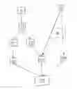
FIG. 1 a schematic image of a first embodiment of a method according to the invention,
FIG. 2 a schematic view of a digital data record of a dental prosthesis designed for the treatment of a patient,
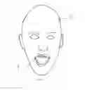
FIG. 3 a schematic view of a two-dimensional digital data record of the face of a patient,
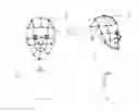
FIG. 4A, B a schematic view of a facial data record with feature points for determining the orientation of the face within the facial data record and
FIG. 5 a schematic view of a visualization of a planned dental prosthesis.
DESIGN EXAMPLES
A first embodiment of a method according to the invention is outlined in FIG. 1.
A three-dimensional tooth data record 1 of a dental prosthesis designed for a patient is provided according to a method step S1. An example of a three-dimensional tooth data record 1 is outlined in FIG. 2.
In order to show the result to be achieved with the dental prosthesis to a patient, according to a method step S2, one facial data record 2 is provided by recording a two-dimensional image of the face of the patient, or a series of facial data records 2 is provided by recording a series of two-dimensional images at short time intervals, wherein one respective facial data record 2 is generated for each image of the series. The one or more two-dimensional images can be recorded by using a camera, for example. The face can be filmed, e.g. with a camera. An example of a facial data record 3 is shown in FIG. 3.
With the aid of a facial recognition method, feature points 3, i.e. characteristic points of the face, such as the corners of the mouth, are identified within the facial data record 2 in a method step S3. In a method step S4, the mouth or the lips are identified in the facial data record 2 on the basis of the recognized feature points 3.
As shown in FIGS. 4A and 4B with two differently oriented faces, a three-dimensional direction 5 of the orientation of the face of the patient in the facial data record 2 is determined on the basis of the feature points 3 in a method step S5. While the direction 5 of the orientation of a front-facing orientation of the face extends perpendicular to the image plane of the facial data record 2 and out of the image plane, for example, the direction 5 for a face recorded in profile lies within the image plane. In method step S5, the three-dimensional orientation of the face is thus deduced from the two-dimensional image of the face.
As outlined in FIG. 5, in a method step S6 following method step S4, an area located between the lips is segmented and cut out as a mouth area 4 within the facial data record 2.
In a method step S7, the tooth data record 1 is rotated and positioned relative to the image plane of the facial data record 2 in such a way that the orientation of the tooth data record 1 matches the determined direction 5 of the orientation of the face and the position matches the position of the mouth area 4.
To do this, the relative orientation of the dental prosthesis to the face is established in method step S8, for example on the basis of a relationship of an orientation of the tooth data record 1 within the image plane to a direction of the orientation of the face within the facial data record 2. The relationship to the orientation of the face in the facial data record 2 can, for instance, be established on the basis of existing teeth that will remain or teeth that are to be replaced. The relevant data is stored, so that the orientation of the tooth data record 1 takes place automatically in method step S7 with the aid of the stored data and the determined orientation 5 of the face within the facial data record 2. Method step S8 therefore does not have to be rerun for every generated facial data record, and for this reason is indicated with dashed lines in FIG. 1.
It is also possible to perform the orientation according to method step S8 once by hand. The thus produced relative orientation of the tooth data record 1 to the direction 5 of the orientation of the face within the facial data record 2 is subsequently stored so that then, in the event of a change in the orientation of the face and a resulting change in the direction 5, the tooth data record can be positioned automatically.
In a method step S9, the oriented three-dimensional tooth data record 1 is displayed behind the facial data record. The data record consisting of the facial data record 2 and the tooth data record 1 with the cut-out mouth area 4 and shown schematically in FIG. 5 is referred to here as the visualization data record.
According to a further development, the tooth data record 2 is edited in a method step S10 prior to merging and displaying the facial data record 2 and the tooth data record 1. The provided tooth data record 2 is typically a data record generated for a CAM method using a CAD method, i.e. a data record that is generated for a computer-aided manufacturing method. A data record intended for use in computer-aided manufacturing merely has to include information pertaining to the shape, i.e. the position of the surface. For the method according to the invention, however, it is advantageous for the appearance of the tooth data record 1 to be as realistic as possible. For this purpose, the tooth data record 1 provided according to method step S1 is edited according to the optional method step S10.
If the facial data record is repeatedly provided at regular time intervals according to method step S2 and at least method steps S3, S4, S5, S6, S7 and S9 are respectively carried out for each new facial data record, the display means is the equivalent of a virtual mirror or the continuously regenerated visualization data record is the equivalent of a virtual mirror image. The patient can move his head and/or open and close his mouth, and see the effect of the planned dental prosthesis from a variety of perspectives. In particular when a recording means for generating the images of the face of the patient is arranged at the smallest possible distance from the display means, the effect of a mirror image, displaying the face of the patient in a current orientation and augmented with the planned dental prosthesis, is achieved.
If the mouth area 4 of the facial data record 2 is not cut out in method step S6, but is instead only identified and partially overlaid with the tooth data record 1, a deviation of a current tooth situation from a planned tooth situation can be visualized. To do this, the mouth area 4 and the tooth data record 1, for example, are displayed simultaneously and in a partially transparent manner; for instance with different colors. This visualization permits easy monitoring of a preparation in real time, or real-time monitoring of the current tooth situation when carrying out a preparation of the tooth situation.
It is also possible to incorporate an additional data record into the visualization data record by orienting the additional data record according to the determined direction 5 of the orientation of the face and the position of the face in the facial data record 2 and superimposing said additional data record on the facial data record 2 and/or the tooth data record 1.
Additional information, e.g. regarding the nerve in the jaw, the mandibular joint, tooth roots, the location of a planned drill hole or the position and orientation of a current drill during use, can be displayed clearly.
LIST OF REFERENCE SIGNS
- 1 Tooth data record
- 2 Facial data record
- 3 Feature points
- 4 Mouth area
- 5 Direction of an orientation of a face within the facial data record
- S1-S9 Method steps
Claims
1. Method for visualizing a tooth situation, wherein an image of the face of a patient is recorded and stored as a facial data record (1),
characterized in that,
feature points (3) within the facial data record (1) are automatically recognized by means of a facial recognition method,
a mouth area (4) located between the lips is recognized automatically on the basis of the feature points (3),
a position of the face in the facial data record (1) and a three-dimensional direction (5) of an orientation of the face in the facial data record (1) is automatically recognized on the basis of the feature points (3),
a virtual tooth data record (2) of the tooth situation is oriented according to the three-dimensional direction (5) of the orientation of the face and positioned according to the position of the face with respect to the facial data record (1),
the mouth area within the facial data record (1) is partially overlaid and/or overlaid and/or replaced by the tooth data record (2) and the result is displayed as a visualization data record.
2. Method according to claim 1, characterized in that the facial data record (1) is two-dimensional or three-dimensional.
3. Method according to claim 1 or 2, characterized in that the tooth data record (2) is three-dimensional.
4. Method according to any of claims 1 to 3, characterized in that the method is rerun at timed intervals.
5. Method according to claim 4, characterized in that the time intervals are no more than 42 ms.
6. Method according to any of claims 1 to 5, characterized in that at least four feature points (3) are automatically identified for the automatic recognition of the mouth area (4).
7. Method according to any of claims 1 to 6, characterized in that at least one three-dimensional additional data record is oriented according to the three-dimensional direction (5) of the orientation of the face and positioned according to the position of the face with respect to the visualization data record, and that the facial data record (1) and/or the tooth data record (2) in the visualization data record is partially overlaid and/or overlaid and/or replaced by the additional data record.
8. Method according to claim 7, characterized in that the additional data record is an image of a tooth root which is segmented from a volume data record and correlated to a current tooth situation with respect to the position.
9. Method according to claim 7 or 8, characterized in that the additional data record is an image of a nerve in the jaw which is segmented from a magnetic resonance tomography image and correlated to a current tooth situation with respect to the position.
10. Method according to any of claims 7 to 9, characterized in that the additional data record is an image of a mandibular joint.
11. Method according to any of claims 7 to 10, characterized in that the additional data record is an image of a drill or a drill hole.
Images & Drawings included:

Sources:
- United States Patent and Trademark Office - verify current appl. status at the USPTO↗
Recent applications in this class:
- » 20250275681 2025-09-04
IMAGE CAPTURING APPARATUS, CONTROL METHOD, AND STORAGE MEDIUM - » 20250255486 2025-08-14
ILLUMINATION DEVICE AND IMAGING DEVICE FOR IMAGING SKIN OF A HUMAN BODY - » 20250255485 2025-08-14
System and Method for Remotely Monitoring Pathological Functions and Conditions with Multi-Spectral, Chip-Based Lidar - » 20250204787 2025-06-26
CAMERA APPARATUS FOR MEDICAL DETECTION - » 20250194931 2025-06-19
ANATOMICAL SURFACE ASSESSMENT METHODS, DEVICES AND SYSTEMS - » 20250194930 2025-06-19
TERMINAL DEVICE AND MEASUREMENT METHOD - » 20250194929 2025-06-19
PERSONAL CAROTID ARTERY STENOSIS DETECTION AND STROKE PREVENTION DEVICE AND PROCESS - » 20250185915 2025-06-12
Digitales Dermatoskop - » 20250160652 2025-05-22
RELEASABLE PORTABLE IMAGING DEVICE FOR MULTISPECTRAL MOBILE TISSUE ASSESSMENT - » 20250152011 2025-05-15
EXAMINATION DEVICE FOR OPTICAL MEDICAL EXAMINATIONS
Recent applications for this Assignee:
- » 20250288479 2025-09-18
MECHANISM FOR ASSEMBLING AND DISASSEMBLING THE HANDLES AND THE INSTRUMENT HOLDER OF A MEDICAL ELEMENT - » 20250252693 2025-08-07
INRAORAL IMAGING BEFORE AND AFTER TREATMENT - » 20250239342 2025-07-24
GENERATING RESTORATION OPTIONS - » 20250218590 2025-07-03
METHOD AND SYSTEM FOR PROCESSING DIGITAL DENTAL IMPRESSIONS - » 20250200863 2025-06-19
REDUCING BANDWIDTH BY PARTIAL RECONSTRUCTION OF OVERLAPPING DENTAL DEPTH IMAGES - » 20250195181 2025-06-19
GENERATING A HIGH-RESOLUTION SCAN OF AN INTRAORAL CAVITY - » 20250185938 2025-06-12
APPARATUSES, SYSTEMS, AND METHODS FOR USING MAGNETIC RESONANCE IMAGING TO ASSESS PERIODONTAL HEALTH - » 20250177105 2025-06-05
DENTAL TREATMENT SYSTEM FOR LOCATING THE APEX OF A TOOTH - » 20250169922 2025-05-29
Means for Managing a Dental Aligner Treatment in Dependence of Magnetic Resonance Data - » 20250162255 2025-05-22
ADDITIVE MANUFACTURING APPARATUS WITH OPTICAL MEANS FOR DIFFUSING/ SCATTERING PROJECTED UV LIGHT TOWARDS PHOTOCURABLE RESIN