Display substrate and display panel
US20180277033A1
2018-09-27
15/544,782
2017-01-19
✅ Patent granted
US 10,607,524 B2
2020-03-31
WO; PCT/CN2017/071683; 20170119
WO; WO2017/206526; 20171207
Kevin M Nguyen
Kinney & Lange, P.A.
2037-01-19
Abstract:
A display panel has a light exit side and includes an infrared light emitting unit for emitting infrared light towards the light exit side of the display panel; and at least three infrared light sensing units provided at different positions for detecting intensity of the infrared light emitted from the light exit side of the display panel and reflected by a human eye.
Inventors:
- Wei Liu 488 🇨🇳 Beijing, China
- Xue Dong 936 🇨🇳 Beijing, China
- Jing Lv 110 🇨🇳 Beijing, China
- Haisheng Wang 644 🇨🇳 Beijing, China
- Xiaoliang Ding 477 🇨🇳 Beijing, China
- Yingming Liu 537 🇨🇳 Beijing, China
- Lijun Zhao 103 🇨🇳 Beijing, China
- Yanling HAN 150 🇨🇳 Beijing, China
- RUI XU 233 🇨🇳 Beijing, China
- Chunwei WU 60 🇨🇳 Beijing, China
- Yanan Jia 56 🇨🇳 Beijing, China
- Changfeng LI 287 🇨🇳 Beijing, China
- Pengpeng WANG 215 🇨🇳 Beijing, China
- Yuzhen GUO 125 🇨🇳 Beijing, China
Assignee:
- BOE TECHNOLOGY GROUP CO., LTD. 20,350 🇨🇳 Beijing, China
Applicant:
Interested in similar patents?
Get notified when new applications in this technology area are published.
Classification:
G09G3/2003 » CPC main
Control arrangements or circuits, of interest only in connection with visual indicators other than cathode-ray tubes for presentation of an assembly of a number of characters, e.g. a page, by composing the assembly by combination of individual elements arranged in a matrix no fixed position being assigned to or needed to be assigned to the individual characters or partial characters Display of colours
G06F3/013 » CPC further
Input arrangements for transferring data to be processed into a form capable of being handled by the computer; Output arrangements for transferring data from processing unit to output unit, e.g. interface arrangements; Input arrangements or combined input and output arrangements for interaction between user and computer; Arrangements for interaction with the human body, e.g. for user immersion in virtual reality Eye tracking input arrangements
H01L27/3234 » CPC further
Devices consisting of a plurality of semiconductor or other solid-state components formed in or on a common substrate including components using organic materials as the active part, or using a combination of organic materials with other materials as the active part with components specially adapted for light emission, e.g. flat-panel displays using organic light-emitting diodes [OLED]; OLED integrated with another component the other component being an imager structure
G09G2320/0261 » CPC further
Control of display operating conditions; Improving the quality of display appearance in the context of movement of objects on the screen or movement of the observer relative to the screen
G09G2360/145 » CPC further
Aspects of the architecture of display systems; Detecting light within display terminals, e.g. using a single or a plurality of photosensors the light originating from the display screen
G09G3/20 IPC
Control arrangements or circuits, of interest only in connection with visual indicators other than cathode-ray tubes for presentation of an assembly of a number of characters, e.g. a page, by composing the assembly by combination of individual elements arranged in a matrix no fixed position being assigned to or needed to be assigned to the individual characters or partial characters
G06F3/01 IPC
Input arrangements for transferring data to be processed into a form capable of being handled by the computer; Output arrangements for transferring data from processing unit to output unit, e.g. interface arrangements Input arrangements or combined input and output arrangements for interaction between user and computer
G09G3/3225 » CPC further
Control arrangements or circuits, of interest only in connection with visual indicators other than cathode-ray tubes for presentation of an assembly of a number of characters, e.g. a page, by composing the assembly by combination of individual elements arranged in a matrix no fixed position being assigned to or needed to be assigned to the individual characters or partial characters using controlled light sources using electroluminescent panels semiconductive, e.g. using light-emitting diodes [LED] organic, e.g. using organic light-emitting diodes [OLED] using an active matrix
H01L27/32 IPC
Devices consisting of a plurality of semiconductor or other solid-state components formed in or on a common substrate including components using organic materials as the active part, or using a combination of organic materials with other materials as the active part with components specially adapted for light emission, e.g. flat-panel displays using organic light-emitting diodes [OLED]
G09G3/3208 » CPC further
Control arrangements or circuits, of interest only in connection with visual indicators other than cathode-ray tubes for presentation of an assembly of a number of characters, e.g. a page, by composing the assembly by combination of individual elements arranged in a matrix no fixed position being assigned to or needed to be assigned to the individual characters or partial characters using controlled light sources using electroluminescent panels semiconductive, e.g. using light-emitting diodes [LED] organic, e.g. using organic light-emitting diodes [OLED]
Description
CROSS-REFERENCE TO RELATED APPLICATION
This application is a Section 371 National Stage Application of International Application No. PCT/CN2017/071683, filed on Jan. 19, 2017, entitled “DISPLAY SUBSTRATE AND DISPLAY PANEL”, which claims priority to Chinese Patent Application No. 201620537196.2, filed on Jun. 3, 2016 with SIPO, incorporated herein by reference in their entirety.
BACKGROUND
Technical Field
Embodiments of the present disclosure relate to a field of display technology, and more particularly, to a display substrate and a display panel.
Description of the Related Art
Some display devices have a function of eye locating (or eye tracking) in order to obtain an eye location of a viewer in real time and adjust a display according to the obtained eye location for a better usage experience.
SUMMARY
According to an aspect of the present disclosure, there is provided a display panel having a light exit side, wherein the display panel comprises:
an infrared light emitting unit for emitting infrared light towards the light exit side of the display panel; and
at least three infrared light sensing units provided at different positions for detecting intensity of the infrared light emitted from the light exit side of the display panel and reflected by a human eye.
According to an exemplary embodiment, the display panel comprises a plurality of infrared light emitting units provided at different positions.
According to an exemplary embodiment, the infrared light emitting unit is a pulse infrared light emitting unit for emitting pulsed infrared light.
According to an exemplary embodiment, the display panel comprises a display area and a peripheral area surrounding the display area, the display area being provided with a plurality of pixel units spaced apart from each other.
According to an exemplary embodiment, the infrared light emitting unit is arranged in the display area, and the infrared light sensing unit is arranged in the peripheral area; or the infrared light emitting unit is arranged in the peripheral area, and the infrared light sensing unit is arranged in the display area.
According to an exemplary embodiment, at least portion of the infrared light emitting units and/or the infrared light sensing units are arranged in the display area, and the infrared light emitting unit and/or the infrared light sensing unit arranged in the display area are located at an interval between adjacent pixel units.
According to an exemplary embodiment, a black matrix is provided at a side of the infrared light emitting unit and/or the infrared light sensing unit arranged in the display area adjacent to the light exit side.
According to an exemplary embodiment, the display panel is a light emitting diode display panel, and the infrared light emitting unit is an infrared light emitting diode provided in the display area.
According to another aspect of the present disclosure, there is provided a display substrate having a light exit side, wherein the display substrate comprises:
an infrared light emitting unit for emitting infrared light towards the light exit side of the display substrate; and
at least three infrared light sensing units provided at different positions for detecting intensity of the infrared light emitted from the light exit side of the display substrate and reflected by a human eye.
According to an exemplary embodiment, the display substrate is an array substrate.
BRIEF DESCRIPTION OF THE DRAWINGS
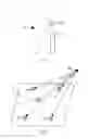
FIG. 1 is a schematic structural side view of a display device having a function of eye locating;
FIG. 2 is a schematic view showing a principle of eye locating of a display panel according to an embodiment of the present disclosure;
FIG. 3 is a schematic view showing a principle of eye locating of another display panel according to an embodiment of the present disclosure;
FIG. 4 is a schematic structural top view of a display panel according to an embodiment of the present disclosure;
FIG. 5 is a schematic structural view of the display panel in partial cross section along a line A-A of FIG. 4;
FIG. 6 is a schematic structural top view of another display panel according to an embodiment of the present disclosure;
FIG. 7 is a schematic structural view of the display panel in partial cross section along a line B-B of FIG. 6;
FIG. 8 is a schematic view showing a structure in partial cross section of a further display panel according to an embodiment of the present disclosure; and
FIG. 9 is a schematic view showing a principle of eye locating of a display substrate according to an embodiment of the present disclosure.
DETAILED DESCRIPTION OF PREFERRED EMBODIMENTS
In order to provide a better understanding of the technical solutions of the present disclosure for those skilled in the art, the present disclosure will be described in further detail with reference to the accompanying drawings and specific embodiments below.
As shown in FIG. 1, a display device having a function of eye locating is provided with a camera 8 on a display panel 1, an image in front of the display panel 1 is acquired by the camera 8, and an eye 9 is recognized from the image by an image analysis technique so as to determine its spatial location.
The image obtained by the above method has a large amount of information, so it needs a complex operation to locate the eye, thus it has a large amount of computation, high cost and low accuracy.
In order to at least partially solve the problem that the eye locating technique has a large amount of computation, high cost and low accuracy, as shown in FIG. 2, according to an embodiment of the present disclosure, there is provided a display panel 1 having a light exit side 2, wherein the display panel 1 includes an infrared light emitting unit 3 for emitting infrared light towards the light exit side 2 of the display panel 1; and at least three infrared light sensing units 4 provided at different positions for detecting intensity of the infrared light emitted from the light exit side 2 of the display panel 1 and reflected by a human eye 9. The display panel 1 of this embodiment can be used for displaying. One side of the display panel functions as a light exit side 2 at which the light for displaying is emitted, and the infrared light emitting unit 3 included in the display panel 1 is used for emitting infrared light and the infrared light sensing unit 4 included in the display panel 1 is used for detecting intensity of the infrared light.
Specifically, as shown in FIG. 5 or 7, the display panel 1 may be formed by assembling two substrates, such as an array substrate 15 and a substrate 16 to be assembled. The infrared light emitting unit 3 and the infrared light sensing unit 4 may be integrated in one or both of the two substrates, so that they are perfectly integrated with the display panel 1, thereby achieving a high integration level. Of course, the infrared light emitting unit 3 and the infrared light sensing unit 4 may also be connected to the array substrate 15 or the substrate 16 to be assembled for example by adhesives, or arranged on a frame of the display panel 1, or the like.
In comparison with most articles in daily life, the eye 9 has a very strong reflecting ability to the infrared light. Therefore, as shown in FIG. 2, the infrared light emitted from the infrared light emitting unit 3 is mainly reflected back by the eye 9 and passes onto the infrared light sensing unit 4. Thus, the intensity of the infrared light received by the infrared light sensing unit 4 is related to a distance between the infrared light sensing unit 4 and the eye 9. Therefore, the distance between the eye 9 and the infrared light sensing unit 4 may be determined by analyzing a detection result from the infrared light sensing unit 4, and a spatial location of the eye 9 relative to the display panel 1 may be determined according to the distances between the eye 9 and the plurality of infrared light sensing units 4. Thus, it can achieve the locating or tracking of the eye 9.
In the display panel 1 of this embodiment, the location of the eye 9 may be determined by the intensity of the infrared light reflected by the eye 9, therefore it does not need complicated image processing, and has a small amount of computation, low cost, and high location accuracy.
Of course, in general, the infrared light is reflected by both (or two) eyes of the same person at the same time. However, since a distance between the two eyes is much smaller than a distance between the eyes 9 and the display panel 1, and the distance between two eyes of each person is in a substantially range, two eyes for the same person can be approximately considered as one reflection point to calculate the location thereof.
Although only one infrared light emitting unit 3 is shown in FIG. 2, the present disclosure is not limited thereto. According to a further embodiment, a plurality of infrared light emitting units 3 may be provided, and may be arranged at different positions.
Specifically, as shown in FIGS. 4 and 6, there are a plurality of infrared light emitting units 3 arranged at different positions. If there is only one infrared light emitting unit 3 and the one infrared light emitting unit 3 is shielded, then it is difficult to detect the location of the eye due to weak intensity of the infrared light emitted into the eye 9. In contrast, if a plurality of infrared light emitting units 3 are provided, then it can ensure that the eye 9 can receive stable infrared light in a variety of different circumstances.
According to an embodiment, the infrared light emitting unit 3 is a pulse infrared light emitting unit for emitting pulsed infrared light.
Specifically, as shown in FIG. 3, the infrared light emitting unit 3 is intended to generate pulsed infrared light. Accordingly, the infrared light sensing unit 4 receives the infrared light which is in the form of a pulse. In this way, by analyzing the number of pulses, the time, the phase, and the like of the infrared light received by the infrared light sensing unit 4, it is possible to more accurately determine the distance between the infrared light sensing unit 4 and the eye 9, and further achieve a more accurate location of the eye 9.
For example, the infrared light emitting unit 3 may intermittently transmit a square-wave pulsed infrared light of, for example, 100 square-wave pulses each transmission. Since a certain amount of time is needed for the infrared light to be reflected to the infrared light sensing unit 4, the infrared light sensing unit 4 should receive only a part of the pulses when the infrared light emitting unit 3 stops emitting the infrared light. For example, 98 square-wave pulses may be received. Moreover, the difference of the number of the pulses is determined by a length of a propagation path of the infrared light. Therefore, the distance between the eye 9 and the infrared light sensing unit 4 can be obtained by analyzing it.
FIG. 4 is a schematic structural top view of a display panel according to an embodiment of the present disclosure, and FIG. 5 is a schematic structural view of the display panel in partial cross section along a line A-A of FIG. 4. As shown in FIGS. 4-5, the display panel 1 includes a display area 11 and a peripheral area 12 surrounding the display area 11, and the display area 11 is provided with a plurality of pixel units 5 spaced apart from each other.
Specifically, the display panel 1 may include a display area 11 for displaying in the middle of the display panel and a peripheral area 12 (for example, a frame or the like) which is not used for displaying, surrounding the display area 11, and display area 11 includes a plurality of pixel units 5 for displaying in the display area 11.
As shown in FIG. 4, the infrared light emitting unit 3 is arranged in the display area 11, and the infrared light sensing unit 4 is arranged in the peripheral area 12.
FIG. 6 is a schematic structural top view of another display panel according to an embodiment of the present disclosure, and FIG. 7 is a schematic structural view of the display panel in partial cross section along a line B-B of FIG. 6. As shown in FIGS. 6-7, the display panel 1 includes a display area 11 and a peripheral area 12 surrounding the display area 11, and the display area 11 is provided with a plurality of pixel units 5 spaced apart from each other.
As shown in FIG. 6, the infrared light emitting unit 3 is arranged in the peripheral area 12, and the infrared light sensing unit 4 is arranged in the display area 11.
In order to avoid interference between the infrared light emitting unit 3 and the infrared light sensing unit 4 caused by too small of a distance, the infrared light emitting unit 3 may be arranged in the display area 11 and the infrared light sensing unit 4 may be arranged in the peripheral area 12, as shown in FIGS. 4-5, or alternatively, the infrared light emitting unit 3 may be arranged in the peripheral area 12 and the infrared light sensing unit 4 may be arranged in the display area 11, as shown in FIGS. 6-7. In general, the infrared light emitting unit 3 and the infrared light sensing unit 4 are respectively arranged in different areas of the display panel, for example, the infrared light emitting unit 3 and the infrared light sensing unit 4 may be respectively arranged in different sub-regions of the display area 11 or the peripheral area 12.
According to a further embodiment, at least a portion of the infrared light emitting units 3 and/or the infrared light sensing units 4 are arranged in the display area 11, and the infrared light emitting unit 3 and/or the infrared light sensing unit 4 arranged in the display area 11 are located at an interval between adjacent pixel units 5. The meaning of the expression “at least a portion of the infrared light emitting units 3 and/or the infrared light sensing units 4 are arranged in the display area 11” refers to at least one infrared light emitting unit 3 being arranged in the display area 11, or at least one infrared light sensing unit 4 being arranged in the display area 11, or at least one infrared light emitting unit 3 and at least one infrared light sensing unit 4 being arranged in the display area 11.
That is to say, as shown in FIG. 5 or 7, if the infrared light emitting unit 3 or the infrared light sensing unit 4 is arranged in the display area 11, then it should be arranged at the respective interval between the adjacent pixel units 5, so as to avoid adversely affecting the display.
As shown in FIG. 8, taking an organic light emitting diode (OLED) display panel as an example, each of the pixel units 5 is provided with one organic light emitting diode 51 for emitting light, a pixel definition layer (PDL) 52 is formed between the respective pixel units 5. Therefore, if the infrared light emitting unit 3 is arranged in the display area 11, then it should be located at the pixel definition layer 52, for example, it is arranged on the pixel definition layer 52.
Further, as shown in FIG. 5 or 7, a black matrix 6 may be provided at a side of the infrared light emitting unit 3 and/or the infrared light sensing unit 4 arranged in the display area 11 adjacent to the light exit side.
That is to say, as shown in FIG. 5 or 7, as for the infrared light emitting unit 3 or the infrared light sensing unit 4 arranged in the display area 11, a black matrix 6 may be provided at a side thereof close to the light exit side of the display panel 1. The provision of the black matrix 6 may better avoid an adverse influence of the infrared light emitting unit 3 or the infrared light sensing unit 4 on the display. Additionally, because the infrared light is different from visible light, it can transmit through the black matrix 6, therefore, the provision of the black matrix 6 would not adversely affect the transmission of the infrared light.
According to an embodiment, the display panel 1 shown in FIG. 4 may be a light emitting diode display panel, and the infrared light emitting unit 3 may be an infrared light emitting diode provided in the display area 11.
According to this embodiment, in the light emitting diode display panel, each pixel unit 5 implements display by means of the light emitting diode. If the infrared light emitting unit is an infrared light emitting diode having a similar structure, then partial structures of the two kinds of diodes may be arranged in the same layer, for example, cathodes or anodes thereof are arranged in the same layer, but light emitting layers are made from different materials. In this way, it can simplify the production process and structure of the product.
The above light emitting diodes may include a quantum dot light emitting diode (QLED) and an organic light emitting diode 51 (OLED), etc., and the infrared light emitting diode may be different from the light emitting diode for displaying in terms of kinds or types, which will not be described in detail herein.
The display panel according to the above embodiments of the present disclosure includes an infrared light emitting unit and an infrared light sensing unit. Since the eye has a stronger reflection ability to the infrared light, the intensity of the infrared light received by the infrared light sensing unit is related to a distance between the infrared light sensing unit and the eye. Therefore, the location of the eye may be determined by analyzing the intensity of the infrared light received by the infrared light sensing unit. Since the display panel determines the location of the eye by the intensity of the infrared light reflected by the eye, it does not need a complicated image processing, and it has a small amount of computation, low cost, and high location accuracy.
According to another aspect of the present disclosure, as shown in FIG. 9, there is provided a display substrate 15 having a light exit side 2, wherein the display substrate includes an infrared light emitting unit 3 for emitting infrared light towards the light exit side 2 of the display substrate 15; and at least three infrared light sensing units 4 provided at different positions for detecting intensity of the infrared light emitted from the light exit side 2 of the display substrate and reflected by a human eye 9.
That is to say, the infrared light emitting unit 3 and the infrared light sensing unit 4 in the display panel 1 according to the above embodiments may be arranged in a same one display substrate 15.
According to an embodiment, the display substrate 15 may be an array substrate. That is to say, if the infrared light emitting unit 3 and the infrared light sensing unit 4 are arranged in the same one substrate, then the substrate may be an array substrate. Since the array substrate is inherently provided with a lot of leads, electrodes, etc., it is relatively convenient to incorporate the infrared light emitting unit 3, the infrared light sensing unit 4, and the like into the array substrate, which is easy to be implemented.
It should be understood that the above embodiments are merely exemplary embodiments for illustrating the principles of the present disclosure, however, the present disclosure is not limited thereto. It will be apparent to those skilled in the art that various modifications and improvements can be made without departing from the principle and spirit of the present disclosure, and such modifications and improvements shall fall within the scope of the present disclosure.
Claims
1. A display panel having a light exit side, wherein the display panel comprises:
an infrared light emitting unit for emitting infrared light towards the light exit side of the display panel; and
at least three infrared light sensing units provided at different positions for detecting intensity of the infrared light emitted from the light exit side of the display panel and reflected by a human eye.
2. The display panel according to claim 1, wherein the display panel comprises a plurality of infrared light emitting units provided at different positions for emitting the infrared light towards the light exit side of the display panel.
3. The display panel according to claim 1, wherein the infrared light emitting unit is a pulse infrared light emitting unit for emitting pulsed infrared light.
4. The display panel according to claim 1, further comprising a display area and a peripheral area surrounding the display area, the display area being provided with a plurality of pixel units spaced apart from each other.
5. The display panel according to claim 4, wherein,
the infrared light emitting unit is arranged in the display area, and the infrared light sensing units are arranged in the peripheral area; or
the infrared light emitting unit is arranged in the peripheral area, and the infrared light sensing units are arranged in the display area.
6. The display panel according to claim 4, wherein the infrared light emitting unit and/or the infrared light sensing units are arranged in the display area and are located at an interval between adjacent pixel units.
7. The display panel according to claim 6, wherein a black matrix is provided at a side of the infrared light emitting unit and/or the infrared light sensing units arranged in the display area adjacent to the light exit side.
8. The display panel according to claim 4, wherein the display panel is a light emitting diode display panel, and the infrared light emitting unit is an infrared light emitting diode provided in the display area.
9. A display substrate having a light exit side, wherein the display substrate comprises:
an infrared light emitting unit for emitting infrared light towards the light exit side of the display substrate; and
at least three infrared light sensing units provided at different positions for detecting intensity of the infrared light emitted from the light exit side of the display substrate and reflected by a human eye.
10. The display substrate according to claim 9, wherein the display substrate is an array substrate.
11. The display panel according to claim 2, wherein the infrared light emitting unit is a pulse infrared light emitting unit for emitting pulsed infrared light.
12. The display panel according to claim 2, further comprising a display area and a peripheral area surrounding the display area, the display area being provided with a plurality of pixel units spaced apart from each other.
13. The display panel according to claim 12, wherein,
the infrared light emitting unit is arranged in the display area, and the infrared light sensing units are arranged in the peripheral area; or
the infrared light emitting unit is arranged in the peripheral area, and the infrared light sensing units are arranged in the display area.
14. The display panel according to claim 12, wherein the infrared light emitting unit and/or the infrared light sensing units are arranged in the display area and are located at an interval between adjacent pixel units
15. The display panel according to claim 14, wherein a black matrix is provided at a side of the infrared light emitting unit and/or one of the infrared light sensing units arranged in the display area adjacent to the light exit side.
16. The display panel according to claim 12 wherein the display panel is a light emitting diode display panel, and the infrared light emitting unit is an infrared light emitting diode provided in the display area.
Images & Drawings included:


Sources:
- United States Patent and Trademark Office - verify current appl. status at the USPTO↗
Similar patent applications:
- » 20110147751
DISPLAY PANEL SUBSTRATE, DISPLAY PANEL, METHOD FOR MANUFACTURING DISPLAY PANEL SUBSTRATE, AND METHOD FOR MANUFACTURING DISPLAY PANEL - » 20100013785
DISPLAY PANEL SUBSTRATE, DISPLAY PANEL, DISPLAY APPRATUS, AND METHOD FOR MANUFACTURING DISPLAY PANEL SUBSTRATE - » 20110175870
DISPLAY PANEL SUBSTRATE, DISPLAY PANEL, AND METHOD FOR MANUFACTURING DISPLAY PANEL SUBSTRATE - » 20120225245
SPACER FORMING METHOD, METHOD OF MANUFACTURING DISPLAY PANEL SUBSTRATE, SPACER, AND DISPLAY PANEL SUBSTRATE - » 20100033666
Display panel substrate, a display panel having the substrate, a method of producing the substrate, and a method of producing the display panel - » 20240147809
TRANSPARENT OLED SUBSTRATE, TRANSPARENT DISPLAY PANEL, ARRAY SUBSTRATE, DISPLAY PANEL, AND DISPLAY DEVICE - » 20190056811
Touch control substrate, touch control panel, display substrate, display panel and display device - » 20050248068
Material for manufacturing display panel substrate assembly and process for manufacturing display panel substrate assembly - » 20130295337
Display panel substrate assembly and an apparatus and method for forming a display panel substrate assembly - » 20110222001
DISPLAY PANEL SUBSTRATE AND DISPLAY PANEL
Recent applications in this class:
- » 20250292713 2025-09-18
OPTICAL COMPENSATION DEVICE, DISPLAY DEVICE, METHOD OF OPTICALLY COMPENSATING DISPLAY DEVICE, AND ELECTRONIC APPARATUS INCLUDING DISPLAY DEVICE - » 20250285574 2025-09-11
SYSTEM AND METHOD FOR A MULTI-PRIMARY WIDE GAMUT COLOR SYSTEM - » 20250273111 2025-08-28
DISPLAY AND DATA CONFIGURATION METHOD THEREOF - » 20250265959 2025-08-21
COLOR MEASURING AND COLOR ADJUSTING DEVICE - » 20250265958 2025-08-21
LIGHT EMITTING DEVICE, IMAGE FORMING DEVICE, DISPLAY DEVICE, IMAGE CAPTURING DEVICE, ELECTRONIC APPARATUS, ILLUMINATION DEVICE, MOVING BODY, AND WEARABLE DEVICE - » 20250259581 2025-08-14
DEVICES AND METHODS FOR CONTROLLING PIXEL DATA PROCESSING - » 20250252885 2025-08-07
IMAGING SYSTEM - » 20250252884 2025-08-07
Apparatus and Method for Inspecting External Appearance of Product - » 20250246111 2025-07-31
SYSTEM AND METHODS TO PROGRAM ACTIVE VEHICLE PAINT SURFACES - » 20250239199 2025-07-24
DISPLAY DEVICE AND COMPUTER READABLE MEDIA
Recent applications for this Assignee:
- » 20250295022 2025-09-18
QUANTUM DOT COMPOSITION, LIGHT-EMITTING ELEMENT, DISPLAY PANEL AND PREPARATION METHOD THEREOF - » 20250295019 2025-09-18
HEAT DISSIPATION FILM, DISPLAY MODULE AND DISPLAY DEVICE - » 20250294987 2025-09-18
DISPLAY PANEL, DISPLAY DEVICE - » 20250294983 2025-09-18
DISPLAY PANEL AND DISPLAY DEVICE - » 20250292736 2025-09-18
DRIVING CIRCUIT, DRIVING METHOD, DRIVING MODULE AND DISPLAY DEVICE - » 20250291336 2025-09-18
COMPUTER-IMPLEMENTED METHOD, APPARATUS FOR MANAGING PRODUCTION OF ONE OR MORE PRODUCTS, AND COMPUTER-PROGRAM PRODUCT - » 20250291215 2025-09-18
CIRCUIT BOARD AND METHOD FOR MANUFACTURING THE SAME, LIGHT-EMITTING SUBSTRATE, BACKLIGHT MODULE, DISPLAY PANEL AND DISPLAY APPARATUS - » 20250287801 2025-09-11
ARRAY SUBSTRATE AND DISPLAY APPARATUS - » 20250287695 2025-09-11
ARRAY PANEL, METHOD OF MANUFACTURING THE SAME AND DISPLAY DEVICE - » 20250285597 2025-09-11
DISPLAY SUBSTRATE AND DISPLAY DEVICE