Four-stroke rotary- piston engine with adjustable compression ratio and adjustable valve control times
US20180306033A1
2018-10-25
15/768,713
2015-10-16
✅ Patent granted
US 11,261,733 B2
2022-03-01
WO; PCT/EP2015/073980; 20151016
WO; WO2017/063710; 20170420
Mary Davis | Paul W Thiede
Andre Roland S.A. | Nikolaus Schibli
2036-03-30
Abstract:
An internal combustion engine is provided using parts that can be produced simply and inexpensively, in which internal combustion engine the fuel is burned optimally by adjustments of compression ratio and valve control times and thus the least possible harmful exhaust gases are emitted while maximum effective power is achieved. Furthermore, all liquid and gaseous fuels can be used.
Inventors:
- Bülent Pulat EVIRGEN 1 🇦🇹 Wien, Austria
- Bilge DREYSEL 1 🇩🇪 Neumünster, Germany
- Bülent Pulat Evirgen 1 🇦🇹 Vienna, Austria
Applicant:
Interested in similar patents?
Get notified when new applications in this technology area are published.
Classification:
F01C20/14 » CPC further
Control of, monitoring of, or safety arrangements for, machines or engines characterised by changing the positions of the inlet or outlet openings with respect to the working chamber using rotating valves
F01B5/00 » CPC further
Reciprocating-piston machines or engines with cylinder axes arranged substantially tangentially to a circle centred on main shaft axis
F01B13/04 IPC
Reciprocating-piston machines or engines with rotating cylinders in order to obtain the reciprocating-piston motion with more than one cylinder
F01B13/045 » CPC main
Reciprocating-piston machines or engines with rotating cylinders in order to obtain the reciprocating-piston motion with more than one cylinder with cylinder axes arranged substantially tangentially to a circle centred on main shaft axis
F02B75/265 » CPC further
Other engines; Engines with cylinder axes coaxial with, or parallel or inclined to, main-shaft axis; Engines with cylinder axes arranged substantially tangentially to a circle centred on main-shaft axis Engines with cylinder axes substantially tangentially to a circle centred on main-shaft axis
F02B75/26 IPC
Other engines Engines with cylinder axes coaxial with, or parallel or inclined to, main-shaft axis; Engines with cylinder axes arranged substantially tangentially to a circle centred on main-shaft axis
F01L7/026 » CPC further
Rotary or oscillatory slide valve-gear or valve arrangements with cylindrical, sleeve, or part-annularly shaped valves with two or more rotary valves, their rotational axes being parallel, e.g. 4-stroke
F01L7/02 IPC
Rotary or oscillatory slide valve-gear or valve arrangements with cylindrical, sleeve, or part-annularly shaped valves
F02B57/04 » CPC further
Internal-combustion aspects of rotary engines in which the combusted gases displace one or more reciprocating pistons Control of cylinder-charge admission or exhaust
F02B57/06 » CPC further
Internal-combustion aspects of rotary engines in which the combusted gases displace one or more reciprocating pistons Two-stroke engines or other engines with working-piston-controlled cylinder-charge admission or exhaust
Description
A four-stroke combustion engine is disclosed, wherein the piston does not—as usually—move up and down in a fixed cylinder, but the piston and the cylinder both move into one direction. This means that, when the piston reaches the bottom dead center, the cylinder slides downwards over the piston until the piston arrives at the top dead center. Then, the piston moves downwards again until it reaches the bottom dead center. This cycle repeats itself in circles continuously.
An adjustable compressor and an adjustable valve time allow for optimal combustion. Due to a springless rotary gate valve with its maximum feed-through cross-section, the best possible fill is achieved.
Thus, highest performance, minimum pollutants in the exhaust gas and the utilization of various fuels become possible.
TECHNICAL IMPLEMENTATION
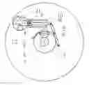
A planet gear (2) rotates around a fixed gear (1) of the same size. The planet gear (2) is supported on an inner disk (3). This disk is supported at the center of the fixed gear (1). A crank (4), which is as long as the radius of the planet gear (2), moves the lever (6) via the piston rod (5). This lever (6) has one end supported on the outer disk (7). The other end is connected to the piston (9) via the bar (8). The cylinder (10) is affixed to the outer rotary disk (7). Using the compression control device (13), the inner disk (3) is shifted along the outer disk (7). Thereby, the piston rod (5) is pulled or pushed, the position of the lever (5) and the compression ratio are changed. (FIG. 1)
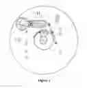
For a simple manufacture, instead of two gears, a gear diameter long lower bar (12), where two gears grip together to the housing, and another gear radius long crank (4) can be employed, as shown in FIG. 2, wherein the support of the inner disk (3) is not at the center, but further out (FIG. 2).
A freewheel attached to the outer disk (7) prevents the disk from rotating backwards.
Functional Principle
By rotating the disks (3 and 7), the crank (4) is set in rotation, pushes the lever (6) via the piston rod (5), which pulls the piston (9) downwards towards the bottom dead center.
When the piston (9) reaches the bottom dead center, it stands still in relation to the rotary movement, because the crank (4) pulls the piston rod (5) backwards. Yet, the cylinder (10) fastened to the outer disk (7) moves on until the piston (9) reaches the top dead center.
When the piston (9) reaches the top dead center, the crank (4) pushes the piston rod (5) again, and in this way the piston (9) moves downwards until it reaches the bottom dead center.
This procedure is repeated once every revolution. This means that the piston (9) moves from the top to the bottom dead center and back to the top dead center once per revolution.
By repositioning the inner disk (3) in relation to the outer disk (7) using the screw/worm gear (13) of the compression control device, the position of the lever (6) and thus the compression ratio is changed.
Every half revolution, the rotary gate valve (11) rotates by one quarter revolution (FIG. 3). Thereby, intake and compression are achieved after one full revolution of the disks, and work and emission after the next revolution. In this way, the 4 strokes (FIG. 3) of a combustion engine come about.
The rotary gate valve (FIG. 3) is a cylinder, wherein the gases enter via the intake passage and exit via the exhaust passage (FIG. 6) at the bottom and are communicated into the combustion chamber via pipe ends (FIG. 3), which are attached on the side at the top.
The quarter valve rotation device is located on top of the rotary gate valve (11) (FIG. 5). Every full revolution, it hits the two opposing pins attached to the fixed outer ring twice and rotates by one quarter revolution every time (FIG. 4).
In this way, the rotary gate valve revolves twice each full revolution (FIG. 3).
By readjusting the quarter valve rotation device (FIG. 5), the valve opening time is adjusted.
Injection nozzles or spark plugs may be arranged at will. In a similar manner, the combustion chamber may take any form.
It is possible to have engines with several cylinders, for example a two-cylinder engine as in FIG. 6.
| Names of the parts |
| 1. fixed gear | |
| 2. planet gear | |
| 3. inner disk | |
| 4. crank | |
| 5. piston rod | |
| 6. lever | |
| 7. outer disk | |
| 8. bar | |
| 9. piston | |
| 10. cylinder | |
| 11. rotary gate valve | |
| 12. lower bar | |
| 13. compression control device screw/worm gear | |
Claims
1. Piston (9) and cylinder (10) as in FIG. 1 moving in one direction.
2. Using two equally large gears (1 and 2) as in FIG. 1 to move the piston (9) and the cylinder (10).
3. Using a rod (12) and a crank (4) as in FIG. 2 to move the piston (9) and the cylinder (10).
4. Changing the compression ratio by readjusting the inner disk (3) in relation to the outer disk (7) as in FIG. 1.
5. Design of the rotary gate valve (11) as in FIG. 3.
6. Design of the quarter rotation device as in FIGS. 4 and 5.
7. Adjustment device for the rotary gate valve (11) as in FIG. 5.
8. Combustion engine according to one of the claims from 1 to 7.
9. Pump according to one of the claims from to 7.
10. Compressor according to one of the claims from 1 to 7.
Images & Drawings included:


Sources:
- United States Patent and Trademark Office - verify current appl. status at the USPTO↗
Recent applications in this class:
- » 20100006059 2010-01-14
Pressure engine, in particular, an internal combustion engine, with an annular structure