TANK
US20180312293A1
2018-11-01
15/936,492
2018-03-27
Abstract:
A tank, including: a foldable liquid container; and a frame, for housing the foldable liquid container, thereby avoiding collapse of the foldable liquid container.
Interested in similar patents?
Get notified when new applications in this technology area are published.
Classification:
B65D1/225 » CPC main
Containers having bodies formed in one piece, e.g. by casting metallic material, by moulding plastics, by blowing vitreous material, by throwing ceramic material, by moulding pulped fibrous material, by deep-drawing operations performed on sheet material; Boxes or like containers with side walls of substantial depth for enclosing contents Collapsible boxes
B65D5/42 » CPC further
Rigid or semi-rigid containers of polygonal cross-section, e.g. boxes, cartons or trays, formed by folding or erecting one or more blanks made of paper Details of containers or of foldable or erectable container blanks
B65D1/22 IPC
Containers having bodies formed in one piece, e.g. by casting metallic material, by moulding plastics, by blowing vitreous material, by throwing ceramic material, by moulding pulped fibrous material, by deep-drawing operations performed on sheet material Boxes or like containers with side walls of substantial depth for enclosing contents
Description
CROSS-REFERENCE TO RELATED APPLICATIONS
This application claims the benefit of priority from Israel Patent Application No. 252013, filed Apr. 27, 2017, the disclosure of which is incorporated herein by reference.
TECHNICAL FIELD
The invention relates to the field of liquid containers. More particularly, the invention relates to a fortified liquid container.
BACKGROUND
A liquid container must be very massive for bearing the hydrostatic pressure of the contained liquid, which without being massive, might likely collapse the liquid container.
There is a long felt need to provide a solution to the above-mentioned and other problems of the prior art.
SUMMARY
A tank, including:
a foldable liquid container; and
a frame, for housing the foldable liquid container, thereby avoiding collapse of the foldable liquid container.
BRIEF DESCRIPTION OF THE DRAWINGS
Embodiments, features, and aspects of the invention are described herein in conjunction with the following drawings:
FIG. 1 depicts a liquid container in two states, according to one embodiment of the invention.
FIG. 2 depicts a frame for housing the liquid container of FIG. 1 in two states, according to one embodiment of the invention.
FIG. 3 depicts a fortified foldable tank in two states, according to one embodiment of the invention.
FIG. 4 is a front sectional view of the tank of FIG. 3.
FIG. 5 is a magnification of a certain region of the tank of FIG. 3.
FIG. 6 is a rear view of the height locking element of FIG. 5.
FIG. 7 depicts placement of two tanks of FIG. 3, one on top of the other.
FIG. 8 is a magnification of the side opening of FIG. 7.
FIG. 9 depicts the first step of using a tank according to another embodiment.
FIG. 10 depicts the second and third steps of using the tank of FIG. 9.
FIG. 11 depicts the fourth step of using the tank of FIG. 9.
The drawings are not necessarily drawn to scale.
DETAILED DESCRIPTION
The invention will be understood from the following detailed description of embodiments of the invention, which are meant to be descriptive and not limiting. For the sake of brevity, some well-known features are not described in detail.
The reference numbers have been used to point out elements in the embodiments described and illustrated herein, in order to facilitate the understanding of the invention. They are meant to be merely illustrative, and not limiting. Also, the foregoing embodiments of the invention have been described and illustrated in conjunction with systems and methods thereof, which are meant to be merely illustrative, and not limiting.
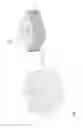
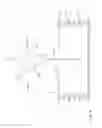
FIG. 1 depicts a liquid container in two states, according to one embodiment of the invention.
A liquid container 10A includes foldable and extendible walls 80; and an opening 16.
Thus liquid container 10A may occupy a small volume, while being empty, or occupy a large volume while containing the liquid.
However, there is yet a problem in that liquid container 10A alone is not sufficient for bearing the hydrostatic pressure of the contained liquid, producing for instance a protrusion 22, and which might likely collapse liquid container 10A.
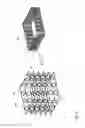
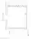
FIG. 2 depicts a frame for housing the liquid container of FIG. 1 in two states, according to one embodiment of the invention.
A frame 10B includes foldable and extendible arms 82.
Thus, frame 10B may provide a small volume, for housing liquid container 10A (not shown) while being empty; or may occupy a large volume, for housing liquid container 10A (not shown) while containing the liquid.
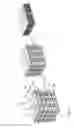
FIG. 3 depicts a fortified foldable tank in two states, according to one embodiment of the invention.
A tank 10C includes liquid container 10A, housed by foldable frame 10B.
The volume of tank 10C is a function of the amount of contained liquid.
The collapse, shown by protrusion 22 of FIG. 1, is avoided by a plurality of horizontal bars 84A, 84B, each being rigid, as presented by rigid corners 86, and horizontally surrounding liquid container 10A.
The distance between each adjacent horizontal bars is equal, whereas the current distance and the current vertical location of each of horizontal bars 84A, 84B is a function of the extent of opening of the crossover arms 82 of foldable frame 10B.
According to another embodiment, frame 10B is not foldable.
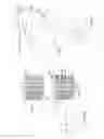
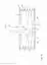
FIG. 4 is a front sectional view of the tank of FIG. 3.
The natural pressure of the contained liquid may be sufficient, for determining the extent of the opening of crossover arms 82.
A float 48, being lifted by the top level of the liquid 46, may lift the top plate 12 of foldable tank 10C, for lifting, the top of frame 10B, through connecting elements 60.
Once liquid 46 is removed from foldable tank 10C, vertical springs 44 may induce folding of frame 10B, which may induce, through connecting elements 60, folding of foldable tank 10C.
The lifting force of float 48 is to be stronger than the folding force of springs 44.
Connecting elements 60 may be rotated, as shown by arrow 90, for canceling the connection, for allowing removing foldable liquid container 10A from frame 10B.
FIG. 5 is a magnification of a certain region of the tank of FIG. 3.
One or more height locking elements 38 may be added to fix the extent of the opening of crossover arms 82.
FIG. 6 is a rear view of the height locking element of FIG. 5.
Height locking element 38 may include a plurality of slits 40, each for housing one horizontal bar, such as 84B, or of arms 82.
FIG. 7 depicts placement of two tanks of FIG. 3, one on top of the other.
Height locking element 38 may strengthen one tank 10C so as to place it below another one.
Liquid may be dispensed from a side cap 76.
FIG. 8 is a magnification of the side opening of FIG. 7.
FIG. 9 depicts the first step of using a tank according to another embodiment.
At the first step, being while tank 10C is folded, the user inserts a bag assembly 92, through top opening 16 of liquid container 10A thereinto.
Bag assembly 92 includes a plate 106, and a bag 96, the bottom 98 thereof being stuck to plate 106.
Plate 106 is rigid, for naturally deploying on the floor of liquid container 10A. Plate 106 may include one or more folds 102, for forming plate 106 to two or more subsidiary plates 94A, 94B, etc., for allowing insertion through opening 16.
FIG. 10 depicts the second and third steps of using the tank of FIG. 9.
At the second step, the user may insert his hand 104, to press plate 106 onto the floor 108 of liquid container 10A, since liquid container 10A is yet folded, thus being low.
Thus, according to this embodiment, tank 10C includes as well bag assembly 92.
At the third step, liquid 18 is poured.
FIG. 11 depicts the fourth step of using the tank of FIG. 9.
Upon filling liquid 18, liquid 18 neatly deploys bag 96, and extends liquid container 10A together with frame 10B.
Thus, in one aspect, the invention is directed to a tank (10C), including:
-
- a foldable liquid container (10A); and
- a frame (10B), for housing the foldable liquid container (10A), thereby avoiding collapse (22) of the foldable liquid container (10A).
The frame (10B) may be vertically foldable.
The frame (10B) may include:
-
- a plurality of rigid peripheral horizontal bars (84A, 84B);
- a plurality of vertically foldable crossover arms (82), for extending between the plurality of rigid peripheral horizontal bars (84A, 84B).
The foldable liquid container (10A) may include a float (48) for enlarging the height of the foldable liquid container (10A) to conform to the amount of the contained liquid (46).
The frame (10B) may include:
-
- a spring (44), for diminishing the height of the frame (10B) to conform to the amount of the contained liquid (46).
The tank (10C) may further include:
-
- a connecting element (60), for connecting the top of the frame (10B) to the top (12) of the foldable liquid container (10A).
The tank (10C) may further include:
-
- at least one height locking element (38), for fixing the height of the frame (10B).
The tank according may further include:
-
- a bag (96), including a plate (106) being stuck thereto, for being inserted into the liquid container (10A) while being folded,
thereby the plate (106) is accessible from the top (16) of the liquid container (10A) for deploying the bottom (98) of the bag (96),
thereby filling of liquid (18) neatly deploys the bag (96) within the liquid container (10A) while unfolding thereof.
In the figures and/or description herein, the following reference numerals (Reference Signs List) have been mentioned:
-
- numeral 10A denotes the foldable liquid container, according to one embodiment of the invention;
- numeral 10B denotes the foldable frame;
- numeral 10C denotes the foldable tank, including at least foldable liquid container 10A and foldable frame 10B;
- numeral 14 denotes the top cap;
- numeral 16 denotes a depression for the top cap, thereby the cap does not protrude, thereby allowing placing one container on the other;
- numeral 18 denotes the liquid;
- numeral 22 denotes a protrusion;
- numeral 24 denotes a grid;
- numeral 26 denotes a hinge between two arms;
- numeral 38 denotes the height locking element;
- numeral 40 denotes a slit, for holding an arm or bar;
- numeral 46 denotes the contained liquid;
- numeral 48 denotes a float;
- numeral 60 denotes a connecting element;
- numeral 72 denotes a lifting plate;
- numeral 76 denotes a side cap;
- numeral 80 denotes the foldable wall of the container;
- numeral 82 denote a crossover foldable extendible arm;
- numerals 84A, 84B and 84C denote peripheral horizontal rigid bars, each forming a closed form;
- numeral 86 denotes a rigid corner;
- numeral 90 denotes rotation or any other disconnecting operation of the connecting element;
- numeral 92 denotes the bag assembly;
- numerals 94A and 94B denote the subsidiary plates;
- numeral 96 denotes the bag;
- numeral 98 denotes the bag's bottom;
- numeral 102 denotes a fold;
- numeral 104 denotes the user's hand;
- numeral 106 denotes the plate of the bag assembly;
- numeral 108 denotes the floor of the liquid container.
The foregoing description and illustrations of the embodiments of the invention has been presented for the purposes of illustration. It is not intended to be exhaustive or to limit the invention to the above description in any form.
Any term that has been defined above and used in the claims, should to be interpreted according to this definition.
The reference numbers in the claims are not a part of the claims, but rather used for facilitating the reading thereof. These reference numbers should not be interpreted as limiting the claims in any form.
Claims
What is claimed is:1. A tank, comprising:
a foldable liquid container; and
a frame, for housing said foldable liquid container,
thereby avoiding collapse of said foldable liquid container.
2. A tank according to claim 1, wherein said frame is vertically foldable.
3. A tank according to claim 2, wherein said frame comprises:
a plurality of rigid peripheral horizontal bars; and
a plurality of vertically foldable crossover arms, for extending between said plurality of rigid peripheral horizontal bars.
4. A tank according to claim 2, wherein said foldable liquid container comprises a float for enlarging a height of said foldable liquid container to conform to an amount of contained liquid.
5. A tank according to claim 2, wherein said frame comprises:
a spring, for diminishing a height of said frame to conform to an amount of contained liquid.
6. A tank according to claim 2, further comprising:
a connecting element, for connecting a top of said frame to a top of said foldable liquid container.
7. A tank according to claim 2, further comprising:
at least one height locking element, for fixing a height of said frame.
8. A tank according to claim 1, further comprising:
a bag (96), comprising a plate being stuck thereto, for being inserted into said liquid container while being folded,
thereby said plate is accessible from a top of said liquid container for deploying a bottom of said bag,
thereby filling of liquid neatly deploys said bag within said liquid container while unfolding thereof.
Images & Drawings included:


Sources:
- United States Patent and Trademark Office - verify current appl. status at the USPTO↗
Similar patent applications:
- » 20210331484
Image-recording apparatus including first tank, second tank connectable to first tank, and head for ejecting liquid supplied from second tank - » 20120111870
INSTALLATION COMPONENT FOR A TANK, APPARATUS FOR DETERMINING A FILL LEVEL OF A TANK, METHOD FOR PRODUCING AN INSTALLATION COMPONENT, TANK AND MOTOR VEHICLE HAVING A TANK - » 20200031133
Image-recording apparatus including first tank, second tank connectable to first tank, and head for ejecting liquid supplied from second tank - » 20230302809
Image-recording apparatus including first tank, second tank connectable to first tank, and head for ejecting liquid supplied from second tank - » 20180244061
Image-recording apparatus including first tank, second tank connectable to first tank, and head for ejecting liquid supplied from second tank - » 20100075200
HIGH-PRESSURE TANK, METHOD OF MANUFACTURING HIGH-PRESSURE TANK, AND MANUFACTURING EQUIPMENT OF HIGH-PRESSURE TANK - » 20090266823
METHOD FOR MANUFACTURING A SEALING BLADDER MADE OF THERMOSETTING POLYMER FOR A TANK CONTAINING A PRESSURIZED FLUID, SUCH AS A COMPOSITE TANK, AND A TANK - » 20110126577
Water tank for refrigerator, manufacturing method of water tank for refrigerator, and refrigerator having water tank for refrigerator - » 20080044517
STIRRED TANK FOR STORING YEAST SLURRY, METHOD OF MANUFACTURING FERMENTED FOODS SUCH AS BEER USING THE STIRRED TANK, AND STIRRING IMPELLER PROVIDED IN THE STIRRED TANK - » 20090101642
FUEL INLET STRUCTURE OF RESIN FUEL TANK, RESIN FUEL TANK HAVING FUEL INLET COMPONENT, AND METHOD FOR PRODUCING THE RESIN FUEL TANK
Recent applications in this class:
- » 20250042597 2025-02-06
Multi-compartment collapsible storage container - » 20230042184 2023-02-09
IMPROVEMENTS IN OR RELATING TO PACKAGING OR CONTAINERS FOR A FOODSTUFF - » 20220274732 2022-09-01
Reinforced Composite Transport Container for Beverages - » 20220194650 2022-06-23
THERMOPLASTIC CONTAINERS COMPRISING AN INTEGRATED SEPARATING COMPONENT - » 20220048666 2022-02-17
FOLDABLE CONTAINER - » 20210047069 2021-02-18
Foldable container and cleaning tool assembly - » 20200255180 2020-08-13
Removable end cap - » 20190375533 2019-12-12
SYSTEM FOR ACTION FIGURE ENTERTAINMENT - » 20190300224 2019-10-03
PACKAGING BOX - » 20140319204 2014-10-30
Eye shield lens dispenser tray