Pump assembly for a hydraulic vehicle braking system
US20180326959A1
2018-11-15
15/778,136
2016-09-28
✅ Patent granted
US 10,875,513 B2
2020-12-29
WO; PCT/EP2016/073076; 20160928
WO; WO2017/089008; 20170601
Thomas W Irvin
Norton Rose Fulbright US LLP | Gerard A. Messina
2036-09-28
Abstract:
A pump assembly for generating a brake pressure in a hydraulic slip-controlled power vehicle braking system, including a fluid sensor between an electric motor and a piston cylinder unit with the aid of which a small brake fluid quantity inadvertently leaking from the piston cylinder unit in the form of leakage is ascertainable before it affects a function of an electronic control or the electric motor.
Assignee:
- Robert Bosch GMBH 19,123 🇩🇪 Stuttgart, Germany
Applicant:
Interested in similar patents?
Get notified when new applications in this technology area are published.
Classification:
B60T13/161 » CPC main
Transmitting braking action from initiating means to ultimate brake actuator with power assistance or drive; Brake systems incorporating such transmitting means, e.g. air-pressure brake systems with fluid assistance, drive, or release the fluid being liquid using pumps directly, i.e. without interposition of accumulators or reservoirs Systems with master cylinder
B60T13/662 » CPC further
Transmitting braking action from initiating means to ultimate brake actuator with power assistance or drive; Brake systems incorporating such transmitting means, e.g. air-pressure brake systems with fluid assistance, drive, or release; Electrical control in fluid-pressure brake systems characterised by specified functions of the control system components
F04B19/22 » CPC further
Machines or pumps having pertinent characteristics not provided for in, or of interest apart from, groups - ; Other positive-displacement pumps of reciprocating-piston type
B60T13/16 IPC
Transmitting braking action from initiating means to ultimate brake actuator with power assistance or drive; Brake systems incorporating such transmitting means, e.g. air-pressure brake systems with fluid assistance, drive, or release the fluid being liquid using pumps directly, i.e. without interposition of accumulators or reservoirs
B60T13/66 IPC
Transmitting braking action from initiating means to ultimate brake actuator with power assistance or drive; Brake systems incorporating such transmitting means, e.g. air-pressure brake systems with fluid assistance, drive, or release Electrical control in fluid-pressure brake systems
F04B17/03 » CPC further
Pumps characterised by combination with, or adaptation to, specific driving engines or motors driven by electric motors
B60T2270/10 » CPC further
Further aspects of brake control systems not otherwise provided for ABS control systems
B60T8/176 » CPC further
Arrangements for adjusting wheel-braking force to meet varying vehicular or ground-surface conditions, e.g. limiting or varying distribution of braking force; Using electrical or electronic regulation means to control braking Brake regulation specially adapted to prevent excessive wheel slip during vehicle deceleration, e.g. ABS
B60T8/4072 » CPC further
Arrangements for adjusting wheel-braking force to meet varying vehicular or ground-surface conditions, e.g. limiting or varying distribution of braking force responsive to a speed condition, e.g. acceleration or deceleration having a fluid pressure regulator responsive to a speed condition comprising an additional fluid circuit including fluid pressurising means for modifying the pressure of the braking fluid, e.g. including wheel driven pumps for detecting a speed condition, or pumps which are controlled by means independent of the braking system Systems in which a driver input signal is used as a control signal for the additional fluid circuit which is normally used for braking
B60T8/4081 » CPC further
Arrangements for adjusting wheel-braking force to meet varying vehicular or ground-surface conditions, e.g. limiting or varying distribution of braking force responsive to a speed condition, e.g. acceleration or deceleration having a fluid pressure regulator responsive to a speed condition comprising an additional fluid circuit including fluid pressurising means for modifying the pressure of the braking fluid, e.g. including wheel driven pumps for detecting a speed condition, or pumps which are controlled by means independent of the braking system; Systems in which a driver input signal is used as a control signal for the additional fluid circuit which is normally used for braking Systems with stroke simulating devices for driver input
B60T13/686 » CPC further
Transmitting braking action from initiating means to ultimate brake actuator with power assistance or drive; Brake systems incorporating such transmitting means, e.g. air-pressure brake systems with fluid assistance, drive, or release; Electrical control in fluid-pressure brake systems by electrically-controlled valves in hydraulic systems or parts thereof
B60T13/745 » CPC further
Transmitting braking action from initiating means to ultimate brake actuator with power assistance or drive; Brake systems incorporating such transmitting means, e.g. air-pressure brake systems with electrical assistance or drive acting on a hydraulic system, e.g. a master cylinder
B60T2270/20 » CPC further
Further aspects of brake control systems not otherwise provided for ASR control systems
B60T2270/30 » CPC further
Further aspects of brake control systems not otherwise provided for ESP control system
B60T13/68 IPC
Transmitting braking action from initiating means to ultimate brake actuator with power assistance or drive; Brake systems incorporating such transmitting means, e.g. air-pressure brake systems with fluid assistance, drive, or release; Electrical control in fluid-pressure brake systems by electrically-controlled valves
B60T13/74 IPC
Transmitting braking action from initiating means to ultimate brake actuator with power assistance or drive; Brake systems incorporating such transmitting means, e.g. air-pressure brake systems with electrical assistance or drive
B60T13/14 IPC
Transmitting braking action from initiating means to ultimate brake actuator with power assistance or drive; Brake systems incorporating such transmitting means, e.g. air-pressure brake systems with fluid assistance, drive, or release the fluid being liquid using accumulators or reservoirs fed by pumps
B60T8/1755 » CPC further
Arrangements for adjusting wheel-braking force to meet varying vehicular or ground-surface conditions, e.g. limiting or varying distribution of braking force; Using electrical or electronic regulation means to control braking Brake regulation specially adapted to control the stability of the vehicle, e.g. taking into account yaw rate or transverse acceleration in a curve
B60T13/146 » CPC further
Transmitting braking action from initiating means to ultimate brake actuator with power assistance or drive; Brake systems incorporating such transmitting means, e.g. air-pressure brake systems with fluid assistance, drive, or release the fluid being liquid using accumulators or reservoirs fed by pumps; Systems with master cylinder; Master cylinder integrated or hydraulically coupled with booster Part of the system directly actuated by booster pressure
B60T13/62 » CPC further
Transmitting braking action from initiating means to ultimate brake actuator with power assistance or drive; Brake systems incorporating such transmitting means, e.g. air-pressure brake systems with fluid assistance, drive, or release; Combined or convertible systems both straight and automatic
B60T8/40 IPC
Arrangements for adjusting wheel-braking force to meet varying vehicular or ground-surface conditions, e.g. limiting or varying distribution of braking force responsive to a speed condition, e.g. acceleration or deceleration having a fluid pressure regulator responsive to a speed condition comprising an additional fluid circuit including fluid pressurising means for modifying the pressure of the braking fluid, e.g. including wheel driven pumps for detecting a speed condition, or pumps which are controlled by means independent of the braking system
B60T17/22 » CPC further
Component parts, details, or accessories of power brake systems not covered by groups , or , or presenting other characteristic features; Safety devices; Monitoring Devices for monitoring or checking brake systems; Signal devices
Description
FIELD OF THE INVENTION
The present invention relates to a pump assembly for a hydraulic vehicle braking system. The pump assembly is in particular provided for generating a brake pressure for actuating a hydraulic power vehicle braking system using external power and/or for generating a brake pressure or for delivering brake fluid for a slip control of a hydraulic vehicle braking system.
BACKGROUND INFORMATION
Slip controls such as anti-lock systems, traction control systems, and electronic stability control systems or electronic stability programs, for which the abbreviations ABS, TCS, ESC and ESP are commonly used, are known for hydraulic vehicle braking systems. For this purpose, wheel brake pressures in wheel brake cylinders of the wheel brakes of hydraulic vehicle braking systems are controlled with the aid of brake pressure build-up valves and brake pressure release valves which are also referred to as inlet and outlet valves. A brake pressure build-up valve and a brake pressure release valve, whose functions may also be combined in one valve, are assigned to each wheel brake cylinder for a wheel-individual pressure control. A brake pressure is generated using muscle power or assisted power with the aid of a brake master cylinder, which may include a brake booster, and/or using external power with the aid of a hydraulic pump which is drivable with the aid of an electric motor. Such slip controls are known per se and are not explained here in greater detail. The unexamined patent application DE 10 2006 026 872 A1 is referred to here as an example.
A hydraulic power vehicle braking system which has a slip control of the type elucidated above is known from the international patent application WO 2012/150 120 A1. In the case of this vehicle braking system, a brake pressure for service braking and slip control is generated using a piston cylinder unit whose piston is drivable with the aid of an electric motor via a mechanical transmission. A brake master cylinder, which is operated via muscle power, is used as a setpoint value indicator for a brake pressure or a brake force during service braking and as a brake pressure generator for assisted braking in the case of failure of the piston cylinder unit including its drive. Hydraulic components of the vehicle braking system, such as solenoid valves, check valves, piston pumps, hydraulic accumulators, damping chambers, and pressure sensors, the already mentioned piston cylinder unit and the brake master cylinder, are accommodated in a hydraulic block and are hydraulically interconnected with one another via bores in the hydraulic block. Electric motors for driving the piston pumps and the piston cylinder unit are also attached on the hydraulic block. Such a hydraulic block is not a required component of the present invention, but is, however, a feature of the exemplary embodiments.
SUMMARY OF THE INVENTION
The pump assembly according to the present invention having the features according to the definition of the species in claim 1 is provided for a hydraulic, slip-controlled and/or power vehicle braking system and is used to generate a brake pressure and/or to deliver brake fluid. The pump assembly includes an electric motor and a hydraulic pump which is drivable with the aid of the electric motor. The hydraulic pump may include a piston cylinder unit or be a piston cylinder unit. A gear pump may, for example, also be used as the hydraulic pump. Furthermore, one or multiple transmissions may be present via which the electric motor drives the hydraulic pump. The transmission may include a reduction gear unit which reduces a rotational speed and converts a torque. The transmission may include a worm gear or any other type of gear which converts a rotary driving motion of the electric motor into a displacement toward a lift drive of a piston in a cylinder (or vice versa) of the hydraulic pump or of a piston cylinder unit.
According to the present invention, the pump assembly includes a fluid sensor for ascertaining brake fluid which leaks from the hydraulic pump or also other hydraulic components. The fluid sensor makes it possible to ascertain leaking brake fluid before the brake fluid, for example, affects or renders inoperative an electronic system for controlling or regulating a brake pressure or a brake force and/or an electronic system for slip control, or before it enters the electric motor. The leaked brake fluid may, for example, be ascertained by measuring the resistance on a circuit board of an electronic system of the pump assembly where the leaked brake fluid reduces an electrical resistance or generates an ohmic connection when entering the circuit board.
The further embodiments and descriptions herein provide advantageous embodiments and refinements of the subject matter of the present invention described herein.
The present invention is explained in greater detail below on the basis of one specific embodiment illustrated in the drawing.
BRIEF DESCRIPTION OF THE DRAWING
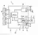
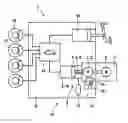
The Figure shows a circuit diagram of a pump assembly according to the present invention.
DETAILED DESCRIPTION
Pump assembly 1 according to the present invention illustrated in the drawing includes an electric motor 2, a transmission 3, and a piston cylinder unit 4 as hydraulic pump 10 which is drivable with the aid of electric motor 2 via transmission 3. Transmission 3 includes a planetary gear set 5 and a worm gear 6. Planetary gear set 5 is accommodated in a housing 7 of electric motor 2 and is used as a reduction gear unit which reduces a rotational speed of electric motor 2 and converts a torque of electric motor 2. Electric motor 2 drives worm gear 6, which may be configured as a ball screw, for example, via planetary gear set 5. Worm gear 6 converts a rotary motion of planetary gear set 5 into a displacement and drives a piston 8 of piston cylinder unit 4 to carry out an axial up and down movement in a cylinder 9 of piston cylinder unit 4. Worm gear 6 may therefore be generally understood as a converter or a conversion gear which converts a rotary motion into a displacement. The up and down movement of piston 8 in cylinder 9 alternatingly displaces brake fluid from cylinder 9 and sucks brake fluid into cylinder 9, whereby a brake pressure is generated and/or brake fluid is delivered, as is known from piston pumps. Piston cylinder unit 9 may therefore also be understood as a piston pump and, in general, as a hydraulic pump 10. Together with electric motor 2 and transmission 3, piston cylinder unit 9 forms a pump assembly 11 for generating a brake pressure for service braking with the aid of a hydraulic power vehicle braking system 12 using external power. Moreover, pump assembly 11 is used to generate a brake pressure and/or to deliver brake fluid for a slip control via hydraulic vehicle braking system 12.
Pump assembly 11 is attached to or in a hydraulic block 13 which is used to mechanically fasten and hydraulically interconnect hydraulic components 14 of a brake force control. In addition to pump assembly 11, such hydraulic components 14 are solenoid valves, check valves, hydraulic accumulators, and damping chambers which are symbolically illustrated in the drawing by one solenoid valve.
Hydraulic wheel brakes 15, whose wheel brake pressures are controllable in a wheel-individual manner with the aid of hydraulic components 14, are connected to hydraulic block 13.
In addition to hydraulic components 14 and pump assembly 11, a brake master cylinder 16, which is actuatable via muscle power and which is used for assisted braking in the case of failure of pump assembly 11, is situated in hydraulic block 13. As already mentioned above, service braking takes place via external power, the brake pressure for service braking being generated with the aid of pump assembly 11. Brake master cylinder 16 is only used for service braking as a setpoint value indicator for a brake pressure which is controlled or regulated via hydraulic components 14. A slip control also takes place via hydraulic components 14 using which a wheel-individual brake pressure control is possible. Such slip controls are, for example, an anti-lock system, a traction control system, an electronic stability control system and/or an electronic stability program, for which the abbreviations ABS, TCS, ESC and ESP are commonly used. Such slip controls and brake force controls for service braking using external power are known per se and are not explained here in greater detail.
Hydraulic blocks 13 are also known from hydraulic power and/or slip-controlled vehicle braking systems. Typically, these involve flat, cuboid-shaped metal blocks, made in most cases from an aluminum alloy, whose thickness is approximately ¼ to ⅓ of a width or length. As a result of machining, hydraulic blocks 13 include diameter-staggered or non-staggered blind holes and/or through holes for accommodating hydraulic components 14, brake master cylinder 16, and piston cylinder unit 4 which are hydraulically interconnected with one another through bores in hydraulic block 13. Instead of a single circuit brake master cylinder 16 (as illustrated), hydraulic block 13 may also include a dual circuit or a multi-circuit brake master cylinder (not illustrated).
On a low-pressure or an unpressurized side, cylinder 9 of piston cylinder unit 4 communicates with a reservoir 17 in which possible leakage fluid is collected, i.e. brake fluid inadvertently leaking from piston cylinder unit 4.
For controlling or regulating a brake force or a brake pressure, hydraulic block 13 includes an electronic control 18 which may also be understood as an electronic control unit. Electronic control 18 controls or regulates hydraulic components 14 and pump assembly 11, a wheel-individual brake force and brake pressure control being possible. Hydraulic block 13 includes a required or at any rate provided installation position in which electronic control 18 is located below piston cylinder unit 4, below transmission 3 and/or below electric motor 2. Electronic control 18 includes a fluid sensor 19 with the aid of which brake fluid inadvertently leaking from piston cylinder unit 4 is determinable prior to entering electric motor 2. An electrical resistance is measured, for example, between two points on a circuit board of electronic control 18 which is rendered electrically conductive by possible brake fluid. The brake fluid quantity is so low in this case that a function of the electronic system is not impaired. Other fluid sensors 19 are also possible. With the aid of fluid sensor 19, an indication for necessary maintenance or repair may be provided already in the case of a small quantity of brake fluid which leaked from cylinder 9 and which does not impair the function of electronic control 18 and of electric motor 2.
Claims
1-9. (canceled)
10. A pump assembly for a hydraulic vehicle braking system, comprising:
an electric motor;
a hydraulic pump which is drivable by the electric motor; and
a fluid sensor to ascertain leaked brake fluid.
11. The pump assembly of claim 10, wherein the fluid sensor is situated between the hydraulic pump and the electric motor.
12. The pump assembly of claim 10, wherein the fluid sensor is situated in an installation position of the pump assembly below the hydraulic pump and/or below the electric motor.
13. The pump assembly of claim 10, wherein the pump assembly includes a transmission which is drivable by the electric motor and which drives the hydraulic pump.
14. The pump assembly of claim 10, wherein the hydraulic pump includes a piston cylinder unit.
15. The pump assembly of claim 10, wherein the pump assembly includes a hydraulic block for mechanically fastening and hydraulically interconnecting the electric motor, the hydraulic pump, and the hydraulic components of a brake force control of a vehicle braking system.
16. The pump assembly of claim 15, wherein the hydraulic block includes a brake master cylinder.
17. The pump assembly of claim 10, wherein the pump assembly includes an electronic control.
18. The pump assembly of claim 17, wherein the electronic control includes the fluid sensor.
Images & Drawings included:
Sources:
- United States Patent and Trademark Office - verify current appl. status at the USPTO↗
Similar patent applications:
- » 20150322931
Hydraulic pump assembly for a hydraulic vehicle brake system, hydraulic vehicle brake system with such a hydraulic pump assembly and method for manufacturing the hydraulic pump assembly - » 20190017502
Piston pump assembly for a hydraulic power vehicle braking system - » 20210122342
Piston pump assembly for a hydraulic power vehicle braking system - » 20150298674
Pump housing arrangement of a hydraulic assembly of a vehicle brake system - » 20160152218
Method for conveying a metered hydraulic volume in a vehicle braking system by means of an electrically driven motor pump assembly and vehicle braking system
Recent applications in this class:
- » 20250206279 2025-06-26
BRAKING APPARATUS FOR VEHICLE - » 20220379861 2022-12-01
HYDRAULIC BLOCK FOR A HYDRAULIC POWER UNIT OF A HYDRAULIC POWER VEHICLE BRAKING SYSTEM - » 20210269004 2021-09-02
Method for operating a brake system, and brake system - » 20190329748 2019-10-31
Hydraulic Control Apparatus and Brake System - » 20160251007 2016-09-01
Pump for integrated brake system - » 20140346852 2014-11-27
Brake system and method of operating - » 20140327296 2014-11-06
Brake device - » 20140265543 2014-09-18
Control of hydraulic brake system and method - » 20140117748 2014-05-01
Rotary pump and braking system having the same - » 20140110996 2014-04-24
Hydraulic brake system
Recent applications for this Assignee:
- » 20250154889 2025-05-15
PRESSURE CONTROL IN AN EXHAUST AFTERTREATMENT SYSTEM - » 20250154580 2025-05-15
ENZYME TRANSLOCATORS IN NANOGAP WITH 3' -ESTERS - » 20250147582 2025-05-08
METHOD FOR DETERMINING AN EYE DISTANCE IN A PAIR OF DATA GLASSES, AND DATA GLASSES - » 20250146568 2025-05-08
DRIVE ASSEMBLY AND VEHICLE HAVING SUCH A DRIVE ASSEMBLY - » 20250146495 2025-05-08
Flexible Pump Assembly for Use in a Fan Drive - » 20250140882 2025-05-01
FUEL CELL SYSTEM HAVING ENERGY RECUPERATION - » 20250137810 2025-05-01
METHOD FOR MATCHING A DIGITAL ROAD MAP - » 20250137033 2025-05-01
DNA UNFOLDING USING A FREE-END TAG FLOW MODIFIER - » 20250119751 2025-04-10
A BLUETOOTH COMMUNICATION METHOD AND SYSTEM - » 20250118116 2025-04-10
Diagnostic Protocol Search With Improved Efficiency