One-side rotating arc lock
US20180328082A1
2018-11-15
16/012,730
2018-06-19
✅ Patent granted
US 10,711,490 B2
2020-07-14
-
-
Kristina R Fulton | Faria F Ahmad
2038-07-13
Abstract:
The present invention discloses a one-side rotating arc lock which comprises an adjusting assembly arranged on a first shell and a strainer arranged on a second shell. The adjusting assembly comprises an arc adjuster rotatably connected with the first shell. The arc adjuster is provided with multiple protrusions in the circumferential direction, used for adjusting the angle between the first and the second shell. Groove is provided on the protrusion. The strainer comprises an adjusting rod which matches the groove for locking the first and the second shell. The angle between the first and the second shell is adjusted through the arc adjuster rotatably connected with the first shell, and locking of the first and the second shell is achieved through the strainer. The one-side rotating arc lock of the preset invention not only has a simple structure and easy to operate, but also facilitates adjustment of the angle.
Inventors:
- Zhiqiang GAO 17 🇨🇳 ShenZhen, China
- Yongjun Zhang 6 🇨🇳 Shenzhen, China
- Guoqiang Li 7 🇨🇳 Shenzhen, China
- Yongjun ZHANG 20 🇨🇳 Guangdong, China
- Guoqiang Li 21 🇨🇳 Guangdong, China
- Zhiqiang Gao 9 🇨🇳 Guangdong, China
Assignee:
- SHENZHEN GLOSHINE TECHNOLOGY CO., LTD. 20 🇨🇳 Shenzhen, China
Applicant:
Interested in similar patents?
Get notified when new applications in this technology area are published.
Classification:
F16B5/0628 » CPC further
Joining sheets or plates, e.g. panels, to one another or to strips or bars parallel to them by means of clamps or clips joining sheets or plates to each other in parallel relationship allowing for adjustment parallel or perpendicular to the plane of the sheets or plates
Y10T292/0867 » CPC further
Closure fasteners; Bolts; Sliding and rotary Spring projected
Y10T292/0868 » CPC further
Closure fasteners; Bolts; Sliding and rotary; Spring projected Combined motion
Y10T292/0886 » CPC further
Closure fasteners; Bolts Sliding and swinging
Y10T292/0887 » CPC further
Closure fasteners; Bolts; Sliding and swinging Operating means
Y10T292/0891 » CPC further
Closure fasteners; Bolts; Sliding and swinging; Operating means Rigid
Y10T292/0893 » CPC further
Closure fasteners; Bolts; Sliding and swinging Spring retracted
Y10T292/57 » CPC further
Closure fasteners Operators with knobs or handles
E05B63/0056 » CPC main
Locks or fastenings with special structural characteristics Locks with adjustable or exchangeable lock parts
E05B63/00 IPC
Locks or fastenings with special structural characteristics or for special use
E05B63/00 IPC
Locks or fastenings with special structural characteristics
E05B9/00 » CPC further
Lock casings or latch-mechanism casings ; Fastening locks or fasteners or parts thereof to the wing
F16B2/185 » CPC further
Friction-grip releasable fastenings; Clamps, i.e. with gripping action effected by positive means other than the inherent resistance to deformation of the material of the fastening using cams, levers, eccentrics, or toggles using levers
F16B5/0092 » CPC further
Joining sheets or plates, e.g. panels, to one another or to strips or bars parallel to them; Joining sheets, plates or panels in abutting relationship characterised by particular locking means with locking means rotating about an axis parallel to the main plane and perpendicular to the abutting edge, e.g. screw, bayonet
F16B5/0614 » CPC further
Joining sheets or plates, e.g. panels, to one another or to strips or bars parallel to them by means of clamps or clips joining sheets or plates to each other in angled relationship
G09F9/307 » CPC further
Indicating arrangements for variable information in which the information is built-up on a support by selection or combination of individual elements in which the desired character or characters are formed by combining individual elements being incandescent filaments
H04M1/0222 » CPC further
Substation equipment, e.g. for use by subscribers; Constructional features of telephone sets; Portable telephone sets, e.g. cordless phones, mobile phones or bar type handsets; Portable telephones comprising a plurality of mechanically joined movable body parts, e.g. hinged housings characterized by the relative motions of the body parts; Foldable telephones, i.e. with body parts pivoting to an open position around an axis parallel to the plane they define in closed position Foldable in two directions, i.e. using a two degree of freedom hinge
Y10T292/089 » CPC further
Closure fasteners; Bolts; Sliding and swinging; Operating means Lever
Y10T292/0863 » CPC further
Closure fasteners; Bolts Sliding and rotary
Y10T292/0864 » CPC further
Closure fasteners; Bolts; Sliding and rotary Combined motion
Y10T292/68 » CPC further
Closure fasteners Keepers
Y10T292/696 » CPC further
Closure fasteners; Keepers With movable dog, catch or striker
Y10T292/702 » CPC further
Closure fasteners; Keepers; With movable dog, catch or striker Pivoted or swinging
Y10T292/705 » CPC further
Closure fasteners; Keepers Adjustable
H04M1/02 IPC
Substation equipment, e.g. for use by subscribers Constructional features of telephone sets
F16B2/18 IPC
Friction-grip releasable fastenings; Clamps, i.e. with gripping action effected by positive means other than the inherent resistance to deformation of the material of the fastening using cams, levers, eccentrics, or toggles
F16B5/06 IPC
Joining sheets or plates, e.g. panels, to one another or to strips or bars parallel to them by means of clamps or clips
F16B5/00 IPC
Joining sheets or plates, e.g. panels, to one another or to strips or bars parallel to them
Description
CROSS REFERENCES TO RELATED APPLICATIONS
This application is a continuation application of PCT Application No. PCT/CN2018/082590 filed on Apr. 11, 2018, which claims the benefit of Chinese Patent Application No. 201710334337.X filed on May 12, 2017. The entire contents of the above applications are hereby incorporated by reference in their entirety.
FIELD OF THE INVENTION
The present invention relates to the technical field of connecting components, in particular to a one-side rotating arc lock.
BACKGROUND OF THE INVENTION
The arc lock in the prior art has a complex structure and is very difficult to maintain. It has a high requirement for the surface in vertical, and the angle is not easy to adjust. Therefore, it is necessary to develop an arc lock that facilitates adjustment of the angle.
SUMMARY OF THE INVENTION
The purpose of the present invention is to provide a one-side rotating arc lock, which has a simple structure, easy to operate, and facilitates adjustment of the angle.
To achieve this goal, the present invention adopts the following technical solutions:
A one-side rotating arc lock which comprises an adjusting assembly arranged on a first shell and a strainer arranged on a second shell. The adjusting assembly comprises an arc adjuster rotatably connected with the first shell. The arc adjuster is provided with multiple protrusions in the circumferential direction, which are used for adjusting the angle between the first shell and the second shell. Groove is provided on the protrusion. The strainer comprises an adjusting rod which matches the groove for locking the first shell and the second shell.
Wherein, the number of the protrusions is nine, the nine protrusions are uniformly arranged along the circumferential direction of the arc adjuster, and the radial lengths of the nine protrusions gradually increase along the circumferential direction of the arc adjuster.
Wherein, the arc adjuster is rotatably connected with the first shell through a rotating shaft, and the rotating shaft is sleeved with bearings on both upper and lower ends of the arc adjuster.
Wherein, the first shell is provided with a receiving groove for mounting the arc adjuster, and an upper part of the receiving groove is provided with a cover plate.
Wherein, the rotating shaft is provided at an upper part of the cover plate with a first knob for adjusting the rotation angle of the arc adjuster and a nut for fixing the first knob.
Wherein, one end of the adjusting rod is provided with a chuck, and the other end of the adjusting rod is provided with a second knob; when locking, press the second knob so that the chuck passes through the groove, rotating the second knob so that the chuck and the groove are alternately arranged to lock the arc adjuster. When unlocking, rotates the second knob so that the chuck is disposed parallel to the groove, and the second knob moves outwards so that the chuck is released from the groove to unlock the arc adjuster.
Wherein, the strainer further comprises a fixing seat fixedly connected with the second shell and a handle screwed with the fixing seat; When locking, rotate the handle so that the handle moves outward relative to the fixing seat until the handle is against the second knob to tighten the adjusting rod and lock the arc adjuster; When unlocking, rotate the handle in the opposite direction, so that the handle moves inward relative to the fixing seat until the handle is separated from the second knob to release the adjusting rod, thereby unlocking the arc adjuster.
Wherein, a spring is sleeved on the adjusting rod, and both ends of the spring are respectively abutted with the second knob and the handle.
The beneficial effects of the present invention: The one-side rotating arc lock of the present invention realizes the adjustment of the angle between the first shell and the second shell through the arc adjuster rotatably connected with the first shell, and realizes locking of the first shell and the second shell through the strainer. The one-side rotating arc lock of the present invention has a simple structure and is easy to operate, also facilitates adjustment of the angle between two surfaces.
BRIEF DESCRIPTION OF THE DRAWINGS
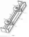
FIG. 1 is a schematic diagram of installation of a one-side rotating arc lock provided by an embodiment of the present invention;
FIG. 2 is a schematic exploded perspective view I of a one-side rotating arc lock provided by an embodiment of the present invention;
FIG. 3 is a schematic exploded perspective view II of a one-side rotating arc lock provided by an embodiment of the present invention;
FIG. 4 is a three-dimensional structural schematic diagram of a one-side rotating arc lock provided by an embodiment of the present invention;
FIG. 5 is a top view of a one-side rotating arc lock provided by an embodiment of the present invention;
FIG. 6 is a top view of an adjusting assembly provided by an embodiment of the present invention;
FIG. 7 is a sectional view taken along line AA in FIG. 6;
FIG. 8 is a three-dimensional structural schematic diagram of an arc adjuster provided by an embodiment of the present invention;
FIG. 9 is a top view of an arc adjuster provided by an embodiment of the present invention;
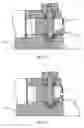
FIG. 10 is a schematic diagram of an unlocked state of a one-side rotating arc lock provided by an embodiment of the present invention;
FIG. 11 is a schematic diagram of a locked state of a one-side rotating arc lock provided by an embodiment of the present invention;
FIG. 12 is a schematic diagram I of an angle adjustment state of an adjusting assembly provided by an embodiment of the present invention;
FIG. 13 is a schematic diagram II of an angle adjustment state of an adjusting assembly provided by an embodiment of the present invention;
FIG. 14 is a schematic diagram III of an angle adjustment state of an adjusting assembly provided by an embodiment of the present invention.
The reference signs in the drawings are as follows:
10: adjusting assembly; 11: arc adjuster; 111: protrusions; 112: groove; 12: rotating shaft; 13: bearing; 14: cover plate; 15: first knob; 16: nut; 20: strainer; 21: adjusting rod; 211: chuck; 22: second knob; 23: fixing seat; 24: handle; 25: spring; 30: first shell; 31: receiving groove; 40: second shell.
DETAILED DESCRIPTION OF THE PREFERRED EMBODIMENT
The technical solution of the present invention will be further described below with reference to FIGS. 1 to 14 and through specific embodiments.
As shown in FIGS. 1 to 7, a one-side rotating arc lock, which comprises an adjusting assembly 10 arranged on a first shell 30 and a strainer 20 arranged on a second shell 40. As shown in FIG. 2, FIG. 6 and FIG. 7, the adjusting assembly 10 comprises an arc adjuster 11 rotatably connected with the first shell 30. The arc adjuster 11 is provided with multiple protrusions 111 along its circumferential direction, for adjusting the angle between the first shell 30 and the second shell 40, a protrusion 111 is provided with a groove 112. As shown in FIG. 3, the strainer 20 comprises an adjusting rod 21 that cooperates with the groove 112 to lock the first shell 30 and the second shell 40.
The adjustment of the angle between the first shell 30 and the second shell 40 is achieved by the arc adjuster 11 which is rotatably connected with the first shell 30, and the locking of the first shell 30 and the second shell 40 is realized by the strainer 20. The structure is simple, the operation is convenient, and it is easy to adjust the angle.
In one embodiment, as shown in FIG. 8 and FIG. 9, the number of the protrusions 111 is nine, and the nine protrusions 111 are uniformly arranged along the circumferential direction of the arc adjuster 11, and the radial lengths of the nine protrusions 111 gradually increases along the circumferential direction of the arc adjuster, so that with every turn of the protrusion 111 of the arc adjuster 11, the angle between the first shell 30 and the second shell 40 is adjusted at a rotation angle of 2.5°. As shown in FIGS. 12 to 14, the angle between the end surface of the arc adjuster and the bottom surface of the first shell is defined as P, P in FIG. 12 is 87.5°, P in FIG. 13 is 90°, and P in FIG. 14 is 92.5°.
In one embodiment, the arc adjuster 11 is rotatably connected with the first shell 30 through a rotating shaft 12. The rotating shaft 12 is sleeved with bearings 13 on both upper and lower ends of the arc adjuster 11. The arrangement of the bearing 13 can reduce the frictional force during the rotation of the arc adjuster 11, so that the arc adjuster 11 can rotate more smoothly.
In one embodiment, the first shell 30 is provided with a receiving groove 31 for mounting the arc adjuster 11, and an upper portion of the receiving groove 31 is provided with a cover plate 14. The cover plate 14 and the receiving groove 31 cooperate to form a cavity, and the arc adjuster 11 is sealed in the cavity so as to protect the arc adjuster 11.
In one embodiment, the rotating shaft 12 is provided at an upper part of the cover plate 14 with a first knob 15 for adjusting the rotation angle of the arc adjuster 11 and a nut 16 for fixing the first knob 15. Preferably, the first knob 15 and the arc adjuster 11 are both fixed on the rotating shaft 12. When the first knob 15 is rotated, the rotation of the arc adjuster 11 can be realized. The disposition of the nut 16 acts as a limit to the first knob 15 and prevents the first knob 15 from being disengaged from the rotating shaft 12.
In one embodiment, an end of the adjusting rod 21 is provided with a chuck 211, and the other end of the adjusting rod 21 is provided with a second knob 22. When locking, the second knob 22 is pressed so that the chuck 211 passes through the groove 112, the second knob 22 is rotated so that the chuck 211 and the groove 112 are alternately arranged to lock the arc adjuster 11. When unlocking, the second knob 22 is rotated so that the chuck 211 is disposed parallel to the groove 112, and the second knob 22 moves outwards so that the chuck 211 is released from the groove 112 to unlock the arc adjuster 11.
In one embodiment, the strainer 20 further comprises a fixing seat 23 fixedly connected with the second shell 40 and a handle 24 screwed connected with the fixing seat 23; when locking, the handle 24 is rotated so that the handle 24 moves outward relative to the fixing seat 23 until the handle 24 is against the second knob 22 to tighten the adjusting rod 21 and lock the arc adjuster 11; when unlocking, the handle 24 is rotated in the opposite direction, so that the handle 24 moves inward relative to the fixing seat 23 until the handle 24 is separated from the second knob 22 to release the adjusting rod 21, thereby unlocking the arc adjuster 11.
In one embodiment, a spring 25 is sleeved on the adjusting rod 21, and both ends of the spring 25 are respectively abutted with the second knob 22 and the handle 24. The spring 25 acts to reset the second knob 22.
The operation method of the one-side rotating arc lock of the present invention is as follows: as shown in FIG. 11, when locking, the second knob 22 is pressed, so that the chuck 211 passes through the groove 112, and the second knob 22 is rotated, so that the chuck 211 and the groove 112 are alternately disposed, and then the handle 24 is rotated, so that the handle 24 is moved relative to the fixing seat 23 until the handle 24 and the second knob 22 collide to tighten the adjusting rod 21, thereby locking the arc adjuster 11; As shown in FIG. 10, when unlocking, the handle 24 is rotated in the opposite direction, so that the handle 24 is moved inward relative to the fixing seat 23 until the handle 24 is separated from the second knob 22 to release the adjusting rod 21 and the second knob 22 is pressed and rotated so as to make the chuck 211 parallel to the groove 112, and the second knob 22 is released, so that the second knob 22 moves outward under the force of the spring 25, and the chuck 211 escapes from the groove 112, thereby unlocking the arc adjuster 11.
The above contents are merely preferred embodiments of the present invention. For those skilled ordinary technicians in the filed, the embodiments of the present invention will have changes in specific implementation manners and application ranges. The content of the present specification should not be construed as a limitation to the present invention.
Claims
What is claimed is:1. A one-side rotating arc lock, wherein the one-side rotating arc lock comprises an adjusting assembly arranged on a first shell and a strainer arranged on a second shell, the adjusting assembly comprises an arc adjuster rotatably connected with the first shell, the arc adjuster is provided with multiple protrusions in the circumferential direction, which are used for adjusting the angle between the first shell and the second shell, grooves are provided on the protrusions, the strainer comprises an adjusting rod which matches the groove for locking the first shell and the second shell.
2. The one-side rotating arc lock according to claim 1, wherein the number of the protrusions is nine, the nine protrusions are uniformly arranged along the circumferential direction of the arc adjuster, and the radial lengths of the nine protrusions gradually increase along the circumferential direction of the arc adjuster.
3. The one-side rotating arc lock according to claim 1, wherein the arc adjuster is rotatably connected with the first shell through a rotating shaft, and the rotating shaft is sleeved with bearings on both upper and lower ends of the arc adjuster.
4. The one-side rotating arc lock according to claim 3, wherein the first shell is provided with a receiving groove for mounting the arc adjuster, and an upper portion of the receiving groove is provided with a cover plate.
5. The one-side rotating arc lock according to claim 4, wherein the rotating shaft is provided at an upper part of the cover plate with a first knob for adjusting the rotation angle of the arc adjuster and a nut for fixing the first knob.
6. The one-side rotating arc lock according to claim 1, wherein an end of the adjusting rod is provided with a chuck, and another end of the adjusting rod is provided with a second knob; when locking, press the second knob so that the chuck passes through the groove, and the second knob is rotated, so that the chuck and the groove are alternately arranged to lock the arc adjuster; when unlocking, rotates the second knob so that the chuck is disposed parallel to the groove, and the second knob moves outwards so that the chuck is released from the groove to unlock the arc adjuster.
7. The one-side rotating arc lock according to claim 6, wherein the strainer further comprises a fixing seat fixedly connected with the second shell and a handle screwed with the fixing seat; when locking, rotate the handle so that the handle moves outward relative to the fixing seat until the handle is against the second knob to tighten the adjusting rod and lock the arc adjuster; when unlocking, rotate the handle in the opposite direction, so that the handle moves inward relative to the fixing seat until the handle is separated from the second knob to release the adjusting rod, thereby unlocking the arc adjuster.
8. The one-side rotating arc lock according to claim 7, wherein a spring is sleeved on the adjusting rod, and both ends of the spring are respectively abutted with the second knob and the handle.
Images & Drawings included:


Sources:
- United States Patent and Trademark Office - verify current appl. status at the USPTO↗
Recent applications in this class:
- » 20250092716 2025-03-20
MODULAR CYLINDRICAL LOCKSET - » 20250027343 2025-01-23
MODULAR CYLINDRICAL LOCKSET - » 20240328206 2024-10-03
ELECTRO-MECHANICAL LOCK CORE - » 20240328205 2024-10-03
PADLOCK WITH VENDING CYLINDER - » 20240271464 2024-08-15
MODULAR DOOR LOCK AND METHODS OF IMPLEMENTING A MODULAR DOOR LOCK - » 20240141696 2024-05-02
UNIVERSAL CHASSIS FOR DOOR HANDLE ASSEMBLIES - » 20240011329 2024-01-11
UNIVERSAL LATCH AND SENSOR SYSTEM - » 20230374821 2023-11-23
Electromechanical multi-directional lock - » 20220412125 2022-12-29
Modular closure system - » 20220251879 2022-08-11
Electro-mechanical lock core
Recent applications for this Assignee:
- » 20250007194 2025-01-02
FLOATING BOARD-TO-BOARD CONNECTOR - » 20240196547 2024-06-13
Arc-shaped lock and splicing screen - » 20240179862 2024-05-30
Arc-shaped lock and display screen assembly - » 20220408577 2022-12-22
LED display screen box - » 20220319359 2022-10-06
Outdoor LED display - » 20220307535 2022-09-29
Locking device - » 20220230565 2022-07-21
LED illuminated floor tile with glass cover - » 20220117099 2022-04-14
Anti-collision device for LED screen - » 20210410300 2021-12-30
Corner protection device and LED display screen cabinet - » 20210358349 2021-11-18
Floor tile screen