Rotary apparatus with protective knife
US20180347562A1
2018-12-06
15/607,722
2017-05-30
✅ Patent granted
US 10,694,653 B2
2020-06-30
-
-
Nathan Cumar
2038-06-26
Abstract:
A rotary apparatus comprises a housing, a rotor, and a face seal. The rotor is mounted for rotation relative to the housing. The housing and the rotor cooperate to provide an annular clearance passage therebetween. The face seal is positioned in communication with the clearance passage and establishes a sealed connection between the housing and the rotor to block ingress of debris from the clearance passage. The housing or the rotor comprises a knife partially defining the clearance passage to cut debris that may enter the clearance passage. The rotary apparatus may be used, for example, in a shaft assembly or a final drive.
Inventors:
- Douglas S. Base 9 🇺🇸 Coffeyville, KS, United States
- Jeffrey S. Turner 20 🇺🇸 Coffeyville, KS, United States
Assignee:
- DEERE & COMPANY 5,300 🇺🇸 Moline, IL, United States
Applicant:
Interested in similar patents?
Get notified when new applications in this technology area are published.
Classification:
F16C33/78 IPC
Parts of bearings; Special methods for making bearings or parts thereof; Sealings of ball or roller bearings with a diaphragm, disc, or ring, with or without resilient members
F16C33/7886 » CPC further
Parts of bearings; Special methods for making bearings or parts thereof; Sealings of ball or roller bearings with a diaphragm, disc, or ring, with or without resilient members mounted outside the gap between the inner and outer races, e.g. sealing rings mounted to an end face or outer surface of a race
F16C2326/20 » CPC further
Articles relating to transporting Land vehicles
B60B27/00 IPC
Hubs
F16C33/72 » CPC further
Parts of bearings; Special methods for making bearings or parts thereof Sealings
F04C2/3564 » CPC main
Rotary-piston machines or pumps having the characteristics covered by two or more groups , , , or having the characteristics covered by one of these groups together with some other type of movement between co-operating members having the movement defined in groups or and relative reciprocation between the co-operating members with vanes reciprocating with respect to the outer member the inner and outer member being in contact along one line or continuous surface substantially parallel to the axis of rotation the surfaces of the inner and outer member, forming the working space, being surfaces of revolution
F04C2/3448 » CPC further
Rotary-piston machines or pumps having the characteristics covered by two or more groups , , , or having the characteristics covered by one of these groups together with some other type of movement between co-operating members having the movement defined in groups or and relative reciprocation between the co-operating members with vanes reciprocating with respect to the inner member with axially movable vanes
F04C2/356 » CPC further
Rotary-piston machines or pumps having the characteristics covered by two or more groups , , , or having the characteristics covered by one of these groups together with some other type of movement between co-operating members having the movement defined in groups or and relative reciprocation between the co-operating members with vanes reciprocating with respect to the outer member
B60B27/0047 » CPC further
Hubs characterised by functional integration of other elements
B60B27/0073 » CPC further
Hubs characterised by sealing means
B60B27/02 » CPC further
Hubs adapted to be rotatably arranged on axle
B60B2900/321 » CPC further
Purpose of invention; Increase in Lifetime
A01B33/14 » CPC main
Tilling implements with rotary driven tools, e.g. in combination with fertiliser distributors or seeders, with grubbing chains, with sloping axles, with driven discs; Tools; Details, e.g. adaptations of transmissions or gearings Attaching the tools to the rotating shaft, e.g. resiliently or flexibly -attached tools
Description
FIELD OF THE DISCLOSURE
The present disclosure relates to a rotary apparatus, and, in particular, to a rotary apparatus having a face seal.
BACKGROUND OF THE DISCLOSURE
A work vehicle (e.g., a four-wheel drive loader, a crawler) at a work site may encounter stringy debris that can wrap around an axle of the work vehicle and compromise a face seal of the axle. For example, it is known for baling twine in a feed lot and magnetic tape in a landfill to wrap around the axle and tighten so as to make its way through a labyrinth to the face seal causing the face seal to leak.
SUMMARY OF THE DISCLOSURE
According to an aspect of the present disclosure, a rotary apparatus comprises a housing, a rotor, and a face seal. The rotor is mounted for rotation relative to the housing. The housing and the rotor cooperate to provide an annular clearance passage therebetween. The face seal is positioned in communication with the clearance passage and establishes a sealed connection between the housing and the rotor to block ingress of debris from the clearance passage. The housing or the rotor comprises a knife partially defining the clearance passage to cut debris that may enter the clearance passage. The rotary apparatus may be used, for example, in a shaft assembly or a final drive.
The above and other features will become apparent from the following description and accompanying drawings.
BRIEF DESCRIPTION OF THE DRAWINGS
The detailed description of the drawings refers to the accompanying figures in which:
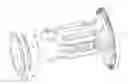
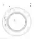
FIG. 1 is a perspective view showing a rotary apparatus configured, for example, as an axle with a housing and a rotor;
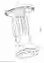
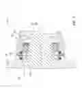
FIG. 2 is a sectional view taken along lines 2-2 of FIG. 1;
FIG. 3 is a sectional view showing an enlarged region of FIG. 2 with a clearance passage between the housing and the rotor and a face seal positioned in communication with the clearance passage, the rotor comprising a knife to cut debris that may enter the clearance passage;
FIG. 4 is an elevational view showing the knife;
FIG. 5 is an elevational view along an axis of rotation of the rotor showing the knife (for clarity of illustration the radially inner portion of the rotor is not shown);
FIG. 6 is an elevational view, with portions broken away, showing an alternative configuration of the knife with a plain cutting edge;
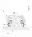
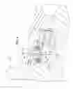
FIG. 7 is a sectional view similar to FIG. 2 showing a second embodiment with the housing comprising a knife;
FIG. 8 is a sectional view showing an enlarged region of FIG. 7;
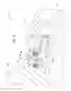
FIG. 9 is an elevational view showing the knife of the second embodiment;
FIG. 10 is an elevational view along an axis of rotation of the housing showing the knife of the second embodiment (for clarity of illustration the radially inner portion of the housing is not shown); and
FIG. 11 is an elevational view, with portions broken away, showing an alternative configuration of the knife of the second embodiment with a plain cutting edge.
DETAILED DESCRIPTION OF THE DRAWINGS
Referring to FIG. 1, a rotary apparatus 10 comprises a housing 12 and a rotor 14 mounted for rotation relative to the housing 12. The rotary apparatus 10 is shown, for example, as an axle assembly of a four-wheel drive loader, with the housing 12 and the rotor 14 configured respectively as the axle housing and the axle of the axle assembly. The rotary apparatus 10 may take a wide variety of configurations, a final drive being another example. The rotary apparatus 10 may be used in a wide variety of applications, such as, for example, in work vehicles (four-wheel drive loaders and crawlers being but two examples) or other vehicles, with the axle assembly being, for example, fixed or oscillatable relative to the vehicle frame.
Referring to FIGS. 2 and 3, the rotary apparatus 10 comprises a face seal 16. The housing 12 and the rotor 14 cooperate to provide an annular clearance passage 18 between the housing 12 and the rotor 14. The face seal 16 is positioned in communication with the clearance passage 18 and establishes a sealed connection between the housing 12 and the rotor 14 to block ingress of debris from the clearance passage 18. The rotor 14 comprises a knife 20 partially defining the clearance passage 18 to cut debris that may enter the clearance passage 18 so that the cut debris may more readily exit the clearance passage 18 out of the rotary apparatus 10 (e.g., by centrifugal force or gravity), thereby protecting the face seal 16.
The face seal 16 is configured, for example, as an axial face seal comprising a first annular member 22a and a second annular member 22b. Each of the first and second annular members 22a, 22b comprises a sealing ring 24, made, for example, of a metal, and a compressible biasing ring 26, made, for example, of an elastomeric material (e.g., fluoroelastomer, hydrogenated nitrile butadiene rubber (HNBR)). Each of the biasing rings 26 is received and compressed in a pocket defined between the respective sealing ring 24 and a portion of the respective housing 12 or rotor 14 (the biasing rings 26 are shown in their relaxed state, although it is to be understood that they will be compressed when the rotor apparatus 10 is assembled). The cross-section of the relaxed state of the biasing rings 26 may be configured in a wide variety of ways. For example, the cross-section may be circular as shown (e.g., on board a four-wheel drive loader or other application) or generally rectangular (e.g., on board a crawler or other application), to name but two examples. The biasing rings 26 press respectively the sealing rings 24 against one another to establish the sealed connection. As the rotor 14 rotates about an axis 28 of the rotor 14, the sealing ring 24 of the first annular member 22a slides against the sealing ring 24 of the second annular member 22b.
The rotary apparatus 10 comprises a bearing 30 in the vicinity of the face seal 16. The face seal 16 is configured to block ingress of debris to the bearing 30 to protect the bearing 30.
The rotor 14 comprises a shaft 32 and a flange 34. The shaft 32 is mounted for rotation in the housing 12 about the axis 28 via the bearing 30 and one or more other bearings (e.g., one other bearing near the other end of the shaft 32). The flange 34 extends radially from the shaft 32, and the knife 20 is mounted to the flange 34. The knife 20 projects axially inwardly away from the flange 34 toward the housing 12. The face seal 16 is positioned radially between the knife 20 and the shaft 32.
The housing 12 comprises an annular recess 36. The knife 20 is annular and projects into the annular recess 36 such that the knife 20 and the recess 36 are axially opposed to one another relative to the axis 28 (FIG. 3). The knife 20 and the recess 36 are correspondingly generally V-shaped in cross-section. The clearance passage 18 comprises a labyrinth 38. The labyrinth 38 is provided at least in part by projection of the knife 20 into the recess 36.
Referring to FIGS. 4 and 5, the knife 20 comprises a serrated cutting edge 40. The knife 20 may be scalloped to provide the annular knife 20 with the serrated cutting edge 40. For example, the knife 20 comprises a plurality of scallops 42 positioned radially inward of the serrated cutting edge 42. In another embodiment, the knife 20 comprises the serrated cutting edge 42 without scallops.
Referring to FIG. 6, in yet another embodiment, the knife 20 may comprise an annular plain cutting edge 40a (without scallops) in place of the serrated cutting edge 40.
Referring to FIGS. 7 and 8, a rotary apparatus 110 is similar to the rotary apparatus 10, except that the housing 12 comprises the knife rather than the rotor 14. As such, some of the reference numbers used in connection with rotary apparatus 10 is used in connection with rotary apparatus 110.
The housing 12 comprises a knife 120 partially defining a clearance passage 118 to cut debris that may enter the clearance passage 118 so that the cut debris may more readily exit the clearance passage 118 out of the rotary apparatus 110 (e.g., by centrifugal force or gravity). The housing 12 comprises an axially outer portion to which the knife 120 is mounted. The knife 120 projects axially outwardly away from the axially outer portion of the housing 12 toward the housing 12. The face seal 16 is positioned radially between the knife 120 and the shaft 32.
The flange 34 comprises an annular recess 136. The knife 120 is annular and projects into the annular recess 136 such that the knife 120 and the recess 136 are axially opposed to one another relative to the axis 28 (FIG. 8). The knife 120 and the recess 136 are correspondingly generally V-shaped in cross-section. The clearance passage 118 comprises a labyrinth 138. The labyrinth 138 is provided at least in part by projection of the knife 120 into the recess 136.
Referring to FIGS. 9 and 10, the knife 120 comprises a serrated cutting edge 140. The knife may be scalloped to provide the knife 120 with the serrated cutting edge 140. For example, the knife 120 comprises a plurality of scallops 142 positioned radially inward of the serrated cutting edge 142. In another embodiment, the knife 120 comprises the serrated cutting edge without scallops.
Referring to FIG. 11, in yet another embodiment, the knife 120 may comprise an annular plain cutting edge 140a (without scallops) in place of the serrated cutting edge 140.
The knife 20, 120 is configured to cut debris that may enter the clearance passage 18, 118 and could encroach upon the face seal 16. As alluded to above, the rotary apparatus 10, 110 may be an axle assembly on a work vehicle (or other vehicle). The work vehicle may encounter baling twine, magnetic tape, or other debris at the worksite, which may tend to wrap around the rotary apparatus 10, 110 and enter the clearance passage 18, 118. In the event that such debris begins to do so, the knife 20, 120 is configured to cut the debris before it becomes tight around and compromises the face seal 16. As the rotor 14 rotates about its axis 28, centrifugal force tends to cause the cut debris to exit the clearance passage 18, 118, and gravity will have a similar effect on the lower side of the rotary apparatus 10, 110.
While the present disclosure has been illustrated and described in detail in the drawings and foregoing description, such illustration and description is to be considered as not restrictive in character. It is to be understood that all changes and modifications that come within the spirit of the present disclosure are desired to be protected. It will be noted that alternative embodiments of the present disclosure may not include all of the features shown and described. Those of ordinary skill in the art may readily devise their own implementations that incorporate one or more of the features of the present disclosure and fall within the spirit and scope of the appended claims.
Claims
What is claimed is:1. A rotary apparatus, comprising
a housing,
a rotor mounted for rotation relative to the housing, the housing and the rotor cooperating to provide an annular clearance passage therebetween, and
a face seal positioned in communication with the clearance passage and establishing a sealed connection between the housing and the rotor to block ingress of debris from the clearance passage, the housing or the rotor comprising a knife partially defining the clearance passage to cut debris that may enter the clearance passage.
2. The rotary apparatus of claim 1, wherein the other of the housing or the rotor comprises an annular recess, and the knife projects into the annular recess.
3. The rotary apparatus of claim 2, wherein the knife and the recess are correspondingly generally V-shaped in cross-section.
4. The rotary apparatus of claim 2, wherein the clearance passage comprises a labyrinth provided at least in part by projection of the knife into the annular recess.
5. The rotary apparatus of claim 2, wherein the knife and the recess are axially opposed to one another relative to an axis of rotation of the rotor.
6. The rotary apparatus of claim 1, wherein the knife is annular.
7. The rotary apparatus of claim 1, wherein the knife comprises a serrated cutting edge.
8. The rotary apparatus of claim 7, wherein the knife comprises a plurality of scallops positioned radially inward of the serrated edge.
9. The rotary apparatus of claim 1, wherein the knife comprises a plain cutting edge.
10. The rotary apparatus of claim 1, wherein the rotor comprises a shaft rotatably positioned in the housing, and the face seal is positioned radially between the knife and the shaft.
11. The rotary apparatus of claim 1, wherein the housing comprises the knife.
12. The rotary apparatus of claim 1, wherein the rotor comprises the knife.
13. The rotary apparatus of claim 12, wherein the rotor comprises a shaft rotatably positioned in the housing and a flange extending radially from the shaft, and the knife is mounted to the flange.
Images & Drawings included:


Sources:
- United States Patent and Trademark Office - verify current appl. status at the USPTO↗
Recent applications in this class:
- » 20190024658 2019-01-24
Rotary compressor - » 20150040608 2015-02-12
Compressor and air conditioner including the same - » 20090291000 2009-11-26
Variable displacement vane pump
Recent applications for this Assignee:
- » 20250293616 2025-09-18
MULTI-OBJECTIVE DESIGN OPTIMIZATION METHOD FOR AUXILIARY RESONANT COMMUTATED POLE INVERTER - » 20250277526 2025-09-04
SEAL TO BE DISPOSED BETWEEN A STRUCTURAL COMPONENT AND AN ENVIRONMENT MODULE - » 20250276564 2025-09-04
WINDOW ASSEMBLIES HAVING TWO OR MORE OPEN CONFIGURATIONS - » 20250261575 2025-08-21
PATH PLANNING - » 20250243831 2025-07-31
FUEL DELIVERY SYSTEM AND METHOD FOR SPARK IGNITED ENGINES OF WORK VEHICLES - » 20250241227 2025-07-31
DUAL FRAME MOUNTED FERTILIZER OPENER WITH INDIVIDUAL DOWNFORCE AND TRAVEL - » 20250221343 2025-07-10
ACTIVE RETURN TUBE AND METHOD OF CONTROLLING SAME - » 20250218232 2025-07-03
SYSTEM AND METHOD FOR COMMUNICATION OF AUTOMATED CONTROL SYSTEM DIAGNOSTICS - » 20250206237 2025-06-26
QUICK RELEASE MOBILE DEVICE HOLDER - » 20250201042 2025-06-19
DIAGNOSTIC TROUBLE CODE DEVICE LINK