Foldable mounting bracket for patio and deck accessories
US20180347747A1
2018-12-06
16/018,262
2018-06-26
✅ Patent granted
US 11,125,379 B2
2021-09-21
-
-
Christopher Garft | Michael McDuffie
2038-06-26
Abstract:
A unique foldable mounting bracket assembly for mounting and securing both vertically and horizontally disposed accessories for decks and patios. Both an upper and lower mounting bracket assembly are required when supporting a vertically disposed cylindrical post. These brackets are mounted to the vertical post and when used in conjunction with the railing of a deck the brackets can be mounted below the top railing horizontal support cross member and above the lower support cross member. When mounting in conjunction with a horizontally disposed accessory, only a single bracket is required; which can be mounted below the top railing horizontal support cross member. The bracket can be mounted such that the horizontally disposed accessory can be stored and not be removed. The mounting bracket assembly can support both vertically and horizontally disposed patio and deck accessories simultaneously. This unique foldable mounting bracket when not in use stows flush against the vertical support post not protruding out of the envelope of the standard 2″×4″ railing horizontal members.
Inventors:
- Lawrence John Thomas 2 🇺🇸 Leesburg, VA, United States
- Mary Catherine Thomas 2 🇺🇸 Leesburg, VA, United States
Applicant:
Interested in similar patents?
Get notified when new applications in this technology area are published.
Classification:
F16M11/04 » CPC further
Stands or trestles as supports for apparatus or articles placed thereon Stands for scientific apparatus such as gravitational force meters; Heads Means for attachment of apparatus; Means allowing adjustment of the apparatus relatively to the stand
A47B5/04 » CPC further
Suspended or hinged panels forming a table; Wall tables foldable
F16M13/02 » CPC main
Other supports for positioning apparatus or articles ; Means for steadying hand-held apparatus or articles for supporting on, or attaching to, an object, e.g. tree, gate, window-frame, cycle
A45B2023/0012 » CPC further
Other umbrellas Ground supported umbrellas or sunshades on a single post, e.g. resting in or on a surface there below
A47G7/041 » CPC further
Flower holders or the like; Devices for supporting flower-pots or cut flowers; Flower tables; Stands or hangers, e.g. baskets, for flowers Flower tables or stands
A45B23/00 IPC
Other umbrellas
A47G7/04 IPC
Flower holders or the like; Devices for supporting flower-pots or cut flowers Flower tables; Stands or hangers, e.g. baskets, for flowers
E04H12/22 » CPC further
Towers; Masts or poles; Chimney stacks; Water-towers; Methods of erecting such structures Sockets or holders for poles or posts
Description
CROSS-REFERENCE TO RELATED APPLICATIONS
This patent claims the benefits under 35 U.S.C. § 119(e) of prior U.S. Provisional Application No. 62/311,564 filed Mar. 22, 2016 and Non-Provisional application Ser. No. 15/461,355
STATEMENT REGARDING FEDERALLY SPONSORED RESEARCH OR DEVELOPMENT
This invention has been created without the sponsorship or funding of any federally sponsored research or development program.
BACKGROUND OF THE INVENTION
1) Field of Invention
This invention relates to a foldable mounting bracket assembly which can be used to secure and support both vertically and horizontally disposed deck and patio accessories. The foldable mounting bracket assembly mounts to a vertically disposed post that supports the deck railing or the like. The vertically disposed deck and patio accessories which can utilize the invention are: umbrellas, flag poles, privacy screens and other items which are attached or utilize a cylindrical vertical pole having a compatible diameter to the vertical cylindrical aperture or through the use of a semi cylindrical taper wedge. The horizontally disposed deck and patio accessories which can utilize the invention are: tables, plant holders, and other items which are attached or utilize the invention. One of the unique features of the invention is that when the bracket is not in use, unlike other brackets, this bracket folds flat against the vertically disposed post that supports the deck railing or the like to which the bracket is mounted.
2) Description of the Related Art
There are many types of brackets assemblies that can support various vertically and horizontally disposed deck or patio accessories. All the current and previous support brackets, when installed, remain in the operational position to either the horizontal railing support or the vertically disposed support post. However the prior art does not fold and limits the support apparatus to remain perpendicular to the mounting surface possibly protruding beyond the envelope of the deck railings. For example see U S. Pat. No. 8,950,723B1 and U.S. Pat. No. 6,003,826. It is the applicants' belief that while these brackets can support various vertically disposed accessories, these brackets remain perpendicular to their mounting surface and do not fold flat against the mounting surface.
BRIEF SUMMARY OF THE INVENTION
This invention relates to a foldable mounting bracket assembly which can be used to secure and support both vertically and horizontally disposed deck and patio accessories. The foldable mounting bracket assembly when supporting vertically disposed deck or patio accessories requires two brackets mounted to the vertical deck railing support post; one bracket mounted below the upper horizontal railing support member and the second bracket mounted above the lower horizontal railing support member. The foldable mounting bracket assembly, when supporting horizontally disposed deck and patio accessories, require only one bracket mounted to the vertical deck railing support post; one bracket mounted below the upper horizontal railing support member. The foldable mounting bracket assemble when supporting both a vertically and horizontally disposed accessories requires two brackets mounted to the vertical deck railing support post; one bracket mounted below the upper horizontal railing support member and the second bracket mounted above the lower horizontal railing support member
BRIEF DESCRIPTION OF THE DRAWINGS
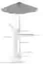
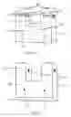
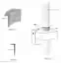
FIG. 1 is a side elevation illustrating the invention deployed in the operational position supporting both a vertically disposed cylindrical support member of an accessory and a horizontally disposed accessory
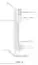
FIG. 2 is a side elevation illustrating the invention in the closed position maintaining and not protruding outside the envelope of the standard 2″×4″ horizontal railing.
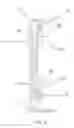
FIG. 3 is a side elevation illustrating the mounting bracket exhibiting the pivot axis of the invention mounted on the deck railing support post
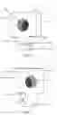
FIG. 4 is an isometric view of the front side of the base portion of the foldable mounting bracket
FIG. 5 is an isometric view of the back side of the base portion of the foldable mounting bracket
FIG. 6 is an isometric view of the front side of the upper rotating mount portion of the foldable mounting bracket
FIG. 7 is an isometric view of the backside of the upper rotating mount portion of the foldable mounting bracket
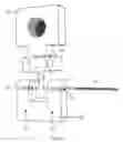
FIG. 8 is an exploded view of the foldable mounting bracket
FIG. 9 is an isometric view of the mounting bracket in the closed position.
FIG. 10 is an isometric view of the mounting bracket in the deployed position.
FIG. 11 is an isometric view of the semi cylindrical locking wedge
FIG. 12 is a side elevation of the semi cylindrical locking wedge
FIG. 13 is an isometric view of a vertically disposed cylindrical post utilizing the semi cylindrical taper wedge
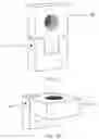
FIG. 14 is a side elevation illustrating the installation of a horizontally disposed accessory using a securing pin
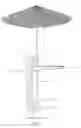
FIG. 15 is a side elevation illustrating the invention deployed in the operational position supporting a horizontally disposed accessory
FIG. 16 is a side elevation illustrating the invention supporting a horizontally disposed accessory which can be stowed parallel to the brackets mounting surface
FIG. 17 is a front plan view showing the horizontally disposed accessory stowed flush against the vertical support post
DETAILED DESCRIPTION OF THE INVENTION
The following FIGS describe the invention with numerical references. Numerical references to specific parts remain the same throughout the different FIGS. Referring first to FIG. 1 the foldable mounting bracket assembly, the invention, can support various vertically supported accessories as indicated by numerical reference 10 and various horizontally supported accessories as indicated by numerical reference 17. In FIG. 1, FIG. 2, FIG. 3, FIG. 14, and FIG. 15 the support floor is numerical reference 11, the deck or patio vertical railing support post is numerical reference 12, the top railing cap is numerical reference 13 and the railing horizontal support members are numerical references 14 and 15. Referring to FIG. 1 and FIG. 14 numerical reference 16a depicts the upper and lower Foldable mounting brackets assembly in the deployed position. In FIG. 1 the vertical cylindrical disposed support member is numerical reference 10 and the horizontal supported accessory is numerical reference 17. In FIG. 2, the foldable mounting bracket in the closed position is shown as numerical reference 16b and in FIG. 3 the foldable mounting bracket assembly rotating axis is numerical reference 20 and the deployed foldable mounting bracket is shown as numerical reference 16a. In FIG. 4 the foldable mounting bracket base portion is numerical reference 23, the aperture for fastening the base to the vertical deck railing support post is numerical reference 24 and the horizontal bore for inserting the knuckle or pivot pin numerical reference 32. The base portion has a front side numerical reference 25, a right side numerical reference 27, an upper side numerical reference 9, with a radius, numerical reference 33, that interfaces the top, numerical reference 29, to the front side, numerical reference 25, and numerical reference 31 is the double eye section or female section of a knuckle joint. In FIG. 5 the foldable mounting bracket base portion has a back side numerical reference 26, a left side numerical reference 28, and an under side numerical reference 30. In FIG. 6 the rotating mounting portion is numerical reference 34, the cylindrical aperture for mounting the vertically and horizontally disposed accessory is numerical reference 43. The rotating mounting portion has a front side numerical reference 35, a right side numerical reference 37and an underside numerical reference 41. In FIG. 7 the rotating mounting portion has backside numerical reference 36, a left side numerical reference 38 and n reference 19 is the top side. In FIG. 6 and FIG. 7 numerical reference 44 is the single eye or male section of the knuckle joint which has a horizontal bore, numerical reference 42, and a continuous radius, numerical reference 45, at the underside connecting the front side numerical reference 35 to numerical reference 36. FIG. 8 illustrates the assembly of the base portion, numerical reference to the rotating mounting portion, numerical reference 34, utilizing the knuckle or pivot pin, numerical reference 40 which provides the rotation of the foldable mounting bracket. In FIG. 9 and FIG. 10 numerical reference 20 is the rotating axis that opens the foldable mounting bracket assembly from the closed position, numerical reference 16b in FIG. 9, to the deployed or open position, numerical reference 16a in FIG. 10. In FIG. 11 and FIG. 12 the depiction of the semi cylindrical tapered wedge is numerical reference 22. In FIG. 13 the foldable mounting bracket in the deployed position is numerical reference 16a, supporting a vertically disposed cylindrical accessory post utilizing the semi cylindrical tapered wedge, compensating for the various diameters of the vertically disposed accessory support posts. In FIG. 2 the foldable mounting bracket assembly is mounted to the, vertically disposed support post. In this configuration the mounting bracket is closed and the mounting bracket assembly, FIG. 9, is parallel to the support post. In FIG. 3 the foldable mounting bracket assembly is mounted to the vertically disposed support post. In this configuration the mounting bracket, FIG. 10, is deployed and the base is parallel to vertically disposed support post and the mounting head is perpendicular to the base and the vertically disposed support post as well as parallel to the deck or the ground. In FIG. 4 item 23 is the base of the bracket assembly and item 24 depicts the apertures for fastening the base to the vertical deck railing support post. The mounting of the bracket assembly to the vertical deck railing support post is accomplished through the use of a variety of fasteners. In FIG. 14 and FIG. 16 the horizontally disposed accessory, item 17, is in the deployed position and secured through item 18, a securing pin. In this configuration the foldable mounting bracket, item 16a, is attached to the vertical support post with the rotating mounting portion, FIGS. 6,7, and 8, reference 34, folding in en upward motion toward the item 14 top railing after the horizontally disposed item is removed. In FIG. 16 And FIG. 17 the horizontally disposed accessory, item 17 is attached in a permanent configuration and is in the stowed position which is parallel to the vertical support post, item 12. In this configuration the top mounting bracket assemble, item 16a is attached to the vertical support post with the rotating mounting portion, reference 34, folding downward toward the lower railing when the mounting bracket assemble is in its stowed position.
Claims
What is claimed:1) A foldable mounting bracket assembly for mounting to a horizontally disposed deck or patio accessory and a vertically disposed deck or patio accessory, the said foldable mounting bracket comprising:
a base portion for fastening said foldable mounting bracket to said vertical deck railing support post and said base portion utilizes a female dovetail having a horizontal bore through said female dove tall for the horizontally mounted pivot pin which interfaces said base portion to said upper rotating mounting head;
b) said upper rotating mounting head with a vertical circular aperture for mounting said deck or patio accessory and said upper rotating mounting head utilizes a male dovetail having a horizontal bore through said male dove tail for said horizontally mounted pivot pin which interfaces said upper rotating mounting head to said base portion;
said horizontally mounted pivot pin which connects said base portion to said upper rotating mounting head and facilitates the 90° rotation from the closed position which is parallel to said vertical mounting post to the deployed position which perpendicular to said railings vertical mounting post as well as parallel to the deck surface;
d) and further comprising a semi cylindrical tapered wedge stabilizes and secures said vertically disposed deck or patio accessories support post;
e) said base portion of said mounting bracket has two circular apertures for receiving fasteners attaching said mounting bracket to said vertical mounting post;
f) said base portion of said mounting bracket when installed its front side and back side are parallel to said vertically disposed support post;
g) said cylindrical wedge has an outer radius that is slightly small than the radius of the circular aperture for mounting the deck or patio accessory;
h) said cylindrical wedge, outer radius is parallel to the radius of said circular aperture and when not in use said wedge can be stored in said circular aperture;
i) semi cylindrical tapered wedge stabilizes said vertically disposed deck or patio accessory support post; and
j) said cylindrical wedge has an inner radius and is tapered from the top to the bottom for securing various diameter accessory support post.
k) said horizontally disposed deck or patio accessory when installed as a permanent accessory said horizontally disposed deck or patio accessory stows parallel to said railing vertical mounting post, and
l) when in the deployed position said horizontally disposed deck or patio accessory is perpendicular to said railing vertical mounting post; and
m) when in the deployed position said horizontally disposed deck or patio accessory is parallel to said deck surface; and
n) when in the deployed position said horizontally disposed deck or patio accessory is secured by either the said vertically disposed deck or patio accessory or the securing pin;
Images & Drawings included:

Sources:
- United States Patent and Trademark Office - verify current appl. status at the USPTO↗
Similar patent applications:
Recent applications in this class:
- » 20250290597 2025-09-18
WALL MOUNTED EQUIPMENT SUPPORT - » 20250290596 2025-09-18
FLOATING MOVING OBJECT AND PROBE MECHANISM - » 20250277558 2025-09-04
BRACKET, SYSTEM AND METHOD FOR HANGING ARTICLES UNDER A STRUCTURE - » 20250271099 2025-08-28
POULTRY FEEDER AND WATERER WITH HANDLE AND SUPPORT PROVIDING AN ADJUSTABLE HEIGHT - » 20250271098 2025-08-28
GRAB BAR ASSEMBLY - » 20250264188 2025-08-21
SEISMIC BRACING YIELD FUSE - » 20250264187 2025-08-21
STAND FOR DISPLAY APPARATUS AND DISPLAY APPARATUS INCLUDING SAME - » 20250243972 2025-07-31
SELF-INSERTING TREE HANGER - » 20250243971 2025-07-31
Mounting system for a tablet - » 20250243970 2025-07-31
RAIL SUPPORTING APPARATUS FOR SUPPORTING TUBULAR RAIL MEMBER FOR BOARDING SPORTS ON A BASE FRAME