Static pressure measurement probe system and associated method
US20180356309A1
2018-12-13
15/990,485
2018-05-25
✅ Patent granted
US 10,724,915 B2
2020-07-28
-
-
Herbert K Roberts
Baker & Hostetler LLP
2038-12-21
Abstract:
A static pressure measurement probe system comprises: a base to be fixed onto the cockpit of an aircraft; at least one local pressure tapping formed through the base and coupled to a pressure measurement sensor; for each local pressure tapping, at least two assemblies each comprising an optical window that is transparent to a laser radiation and a laser anemometry probe configured to take anemometry measurements in an imaginary cylinder centred on the local pressure tapping and of a diameter less than 3 cm and of a height less than 4 cm counted from the outer end of the local pressure tapping, so that the measurements are within the airflow limit layer.
Inventors:
- Jean-Pierre Schlotterbeck 21 🇫🇷 Rochefort-Samson, France
- Jean-Philippe Pineau 5 🇫🇷 Landes le Gaulois, France
- Jean-Pierre SCHLOTTEBECK 1 🇫🇷 ROCHEFORT-SAMSON, France
Assignee:
- THALES 1,189 🇫🇷 Courbevoie, France
Applicant:
Interested in similar patents?
Get notified when new applications in this technology area are published.
Classification:
G01L27/002 » CPC further
Testing or calibrating of apparatus for measuring fluid pressure Calibrating, i.e. establishing true relation between transducer output value and value to be measured, zeroing, linearising or span error determination
G01P13/025 » CPC further
Indicating or recording presence, absence, or direction, of movement; Indicating direction only, e.g. by weather vane indicating air data, i.e. flight variables of an aircraft, e.g. angle of attack, side slip, shear, yaw
G01P21/025 » CPC further
of speedometers for measuring speed of fluids; for measuring speed of bodies relative to fluids
G01L27/00 IPC
Testing or calibrating of apparatus for measuring fluid pressure
G01P13/02 IPC
Indicating or recording presence, absence, or direction, of movement Indicating direction only, e.g. by weather vane
G01P21/02 IPC
of speedometers
G01P5/14 » CPC further
Measuring speed of fluids, e.g. of air stream; Measuring speed of bodies relative to fluids, e.g. of ship, of aircraft by measuring differences of pressure in the fluid
G01L19/00 IPC
Details of, or accessories for, apparatus for measuring steady or quasi-steady pressure of a fluent medium insofar as such details or accessories are not special to particular types of pressure gauges
G01S17/88 » CPC further
Systems using the reflection or reradiation of electromagnetic waves other than radio waves, e.g. lidar systems Lidar systems specially adapted for specific applications
G01C5/06 » CPC further
Measuring height; Measuring distances transverse to line of sight; Levelling between separated points; Surveyors' levels by using barometric means
G01L19/0092 » CPC further
Details of, or accessories for, apparatus for measuring steady or quasi-steady pressure of a fluent medium insofar as such details or accessories are not special to particular types of pressure gauges Pressure sensor associated with other sensors, e.g. for measuring acceleration or temperature
G01S17/58 » CPC further
Systems using the reflection or reradiation of electromagnetic waves other than radio waves, e.g. lidar systems; Systems using the reflection of electromagnetic waves other than radio waves; Systems of measurement based on relative movement of target Velocity or trajectory determination systems; Sense-of-movement determination systems
G01L19/0007 » CPC main
Details of, or accessories for, apparatus for measuring steady or quasi-steady pressure of a fluent medium insofar as such details or accessories are not special to particular types of pressure gauges Fluidic connecting means
G01P5/26 » CPC further
Measuring speed of fluids, e.g. of air stream; Measuring speed of bodies relative to fluids, e.g. of ship, of aircraft by measuring the direct influence of the streaming fluid on the properties of a detecting optical wave
Description
CROSS-REFERENCE TO RELATED APPLICATIONS
This application claims priority to foreign French patent application No. FR 1700605, filed on Jun. 8, 2017, the disclosure of which is incorporated by reference in its entirety.
FIELD OF THE INVENTION
The present invention relates to a static pressure measurement probe system and an associated method.
The present invention lies within the field of anemobarometry for aeroplanes (military or civilian).
BACKGROUND
A fundamental law of thermodynamics governs lift and therefore the support capacity in the air:
Fz=½ρV2SCz
in which:
Fz represents the lift, in N;
ρ represents the density of the fluid, in this case air, in kg/m3;
V represents the velocity of the probe system relative to the surrounding air, in m/s;
S represents a surface exposed to the airflow, in m2;
Cz represents an adimensional lift coefficient.
Conventionally, it is known practice to not measure the density p of the air or the true air speed or TAS, because a simpler method has been used since the beginnings of aviation based on the conventional speed or CAS, the acronym for “Calibrated AirSpeed”, obtained by a difference between a total pressure (stop pressure) supplied by a Pitot probe and a static pressure tapped tangentially to the airflow, considered as close as possible to the ambient pressure in the absence of the aeroplane.
The anemobarometric measurement systems installed on military or civilian aeroplanes exhibit measurements that are likely to be falsified in the case of icing, because of the protuberant nature of the probes used, such as Pitot probes, incidence probes and sideslip probes. Use is therefore conventionally made of devices for de-icing and preventing icing of these probes by reheating, which can result in problems of reliability and lead to a significant electrical consumption.
It is known practice to mitigate these problems by means of flush systems (non-protuberant systems) that for example use:
the parietal technology, i.e. a plurality of local pressure probes (taking a pressure more or less close to the static pressure) distributed over the skin of the aircraft, which, combined with a complex calibration and subject to major installation precautions makes it possible to provide the static pressure, the angle of incidence or AOA, the acronym for “Angle Of Attack”, the conventional speed or CAS, the acronym for “Calibrated AirSpeed”, and the SideSlip Angle, or SSA;
the LiDAR (the acronym for “Light Detection and Ranging”) technology that makes it possible to perform a direct measurement of the air speed outside of the 3D (vectorial) limit layer using laser beams, making it possible to then obtain the True AirSpeed TAS, the Angle Of Attack AOA and the SideSlip Angle SSA;
the technology based on ultrasound probes which provides vector speed information; and
the hybrid technology which combines several of the technologies cited above, for example FR2994273 or FR3035209 thus creating multifunction probes.
These non-protuberant systems exhibit drawbacks of high cost, of installation difficulty because they are generally sensitive to the imperfections of the aeroplane skin, and sometimes of completeness of the flight domain.
Furthermore, in the military field, electromagnetic and thermal stealth are an additional issue, because the reheated protuberant probes exhibit a significant RADAR echo and an infrared-detectable thermal emission.
SUMMARY OF THE INVENTION
One aim of the invention is to mitigate the abovementioned problems.
There is proposed, according to one aspect of the invention, a static pressure measurement probe system comprising:
a base intended to be fixed onto the cockpit of an aircraft;
at least one local pressure tapping formed through the base and coupled to a pressure measurement sensor;
for each local pressure tapping, at least two assemblies each comprising an optical window that is transparent to a laser radiation and a laser anemometry probe configured to take anemometry measurements in an imaginary cylinder centred on the static pressure tapping and of a diameter less than 3 cm and of a height less than 4 cm counted from the outer end of the local pressure tapping, so that the measurements are within the airflow limit layer, to compensate the effects of the measured local air speed on the static pressure.
Such a local pressure measurement probe system is insensitive to icing and is more resistant to wear and to impacts.
Furthermore, this system remains efficient throughout the flight domain of a manoeuvring military aircraft, has a RADAR signature and a thermal signature that are low, all at a reduced cost.
In one embodiment, the two assemblies, the local pressure tapping and the pressure measurement sensor are arranged in an imaginary cylinder, centred on the pressure tapping, and of a diameter less than 20 cm.
Thus, there are no longer pneumatic tubes to be installed in the aeroplane to link the sensor to the probe.
In one embodiment, the laser anemometry probes are micro-lidars.
Thus, it is possible to obtain the components of the air speed vector as close as possible (a few cm at most) to the local pressure measurement hole.
For example, the micro-lidars are configured to emit a laser radiation at a wavelength of between 1.4 μm and 1.8 μm and of optical power lying between 1 W and 5 W.
In one embodiment, the optical windows have a diameter at most equal to 3 cm.
There is also proposed, according to another aspect of the invention, an aircraft comprising a probe system as previously described.
There is also proposed, according to another aspect of the invention, a method for determining the static pressure by compensation of the measured local pressure by means of a measurement of the air speed at the measurement point.
Thus, it is possible to associate a pressure correction as a function of the modulus and of the orientation of the local airflow.
BRIEF DESCRIPTION OF THE DRAWINGS
The invention will be better understood on studying a few embodiments described as nonlimiting examples and illustrated by the attached drawings in which FIGS. 1 and 2 schematically illustrate a static pressure measurement probe system according to an aspect of the invention.
In all the figures, the elements that have the same references are similar.
DETAILED DESCRIPTION
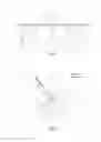
FIG. 1 shows, in a cross sectional view, a static pressure measurement probe system according to an aspect of the invention.
The static pressure measurement probe system comprises a base 1 intended to be fixed onto the cockpit of an aircraft, and at least one local pressure tapping 2 formed through the base and coupled to a pressure measurement sensor 3, in this case a single local pressure tapping 2 is represented.
For each local pressure tapping, in this case the single local pressure tapping 2, two assemblies 4, 5 each comprise a respective optical window 6, 7 that is transparent to a laser radiation and a laser anemometry probe 8, 9 configured to take anemometry measurements by means of their laser beam 10, 11 in an imaginary cylinder 12 centred on the local pressure tapping 2 and of a diameter less than 3 cm and of a height less than 4 cm counted from the outer end of the local pressure tapping 2, so that the measurements are within the airflow limit layer, to compensate the effects of the measured local air speed on the static pressure.
Preferentially, the two assemblies 4, 5, the static pressure tapping 2 and the pressure measurement sensor 3 are arranged in an imaginary cylinder 13 internal to the probe system, centred on the pressure tapping 2, and of a diameter less than 20 cm.
The laser anemometry probes 8, 9 can be Doppler micro-lidars that make it possible to perform the measurement of the projections of the local air speed vector on the optical axes (laser beam 10,11).
Such micro-lidars can emit a laser at a wavelength of between 1.4 μm and 1.8 μm and of optical power lying between 1 W and 5 W.
An aeroplane skin plate 14, comprising optical windows 6, 7, covers the outer part of the probe system, intended to be located on the outer surface of the aircraft on which it is intended to be mounted. This plate is conventionally designed to minimize the local turbulences of the airflow in the vicinity of the pressure tapping which will have the effect of simplifying the law of local pressure measurement correction from the air speed measurement performed by the lidars.
FIG. 2 shows, in a plan view, the static pressure measurement probe assembly of FIG. 1, as well as an angle α between the speed vector V of the air and a reference axis 15 of the probe assembly.
The local speed vector, at the measurement hole of the static pressure Ps tapping 2, is practically parallel to the aeroplane skin plate 14 covering the probe system. The flight domain varies this vector in modulus and in angle α relative to the reference axis of the probe system. Upon the installation of the probe system, it is essential to ensure that the range of variation of a does not exceed the angle made between them by the axes of measurement of the laser anemometry probes 8, 9, because each laser anemometry probe 8, 9 performs a measurement of the conventionally unsigned projection V8 and V9 of the vector on its axis, in order to avoid ambiguity in the computation of the angle α.
Having two components on the two measurement axes of the two respective laser beams 10, 11, it is possible to compute (with the index “loc” meaning that each probe 8, 9 takes a different measurement which depends on its place of installation or of location), the following elements:
the modulus of the speed vector: Vloc
the angle (signed) αloc relative to the reference axis of the probe system;
if the angle between the laser anemometry probes 7 and 8 is 90° and the measurement axes of the probes are symmetrical relative to the reference axis,
Vloc=(V82+V92)0.5
αloc=Arctan(V8/V9)−45°
In in-flight testing, a correction of the static pressure measurement Psloc with the computed angle αloc and the modulus of the local speed Vloc is identified. In a simple (first order) case, it is possible to give a relationship of the type:
Pscorrected=Psmeasured+a·Vloc+b·αloc
It is also possible to envisage a more complex correction resulting from a second order calibration taking into account terms in Vloc2 and αloc2 and/or crossed Vloc·αloc.
For the orders of magnitude, it is considered that the range of variation of α is +/−45° around the reference axis 15, that the point of convergence of the axes of the laser beams 10, 11 of the laser anemometry probes 8, 9 is situated at a distance from the pressure measurement hole or static pressure tapping 2 lying between 1 and 3 cm, and that the diameter of the optical windows or portholes 6, 7 is at most equal to 3 cm.
Claims
1. A static pressure measurement probe system comprising:
a base intended to be fixed onto the cockpit of an aircraft;
at least one local pressure tapping formed through the base and coupled to a pressure measurement sensor;
for each local pressure tapping, at least two assemblies each comprising an optical window that is transparent to a laser radiation and a laser anemometry probe configured to take anemometry measurements in an imaginary cylinder centred on the local pressure tapping and of a diameter less than 3 cm and of a height less than 4 cm counted from the outer end of the local pressure tapping, so that the measurements are within the airflow limit layer, to compensate the effects of the measured local air speed on the static pressure.
2. The system according to claim 1, wherein the two assemblies, the local pressure tapping and the pressure measurement sensor are arranged in an imaginary cylinder, centred on the pressure tapping, and of a diameter less than 20 cm.
3. The system according to claim 1, wherein the laser anemometry probes are micro-lidars.
4. The system according to claim 3, wherein the micro-lidars are configured to emit a laser radiation at a wavelength of between 1.4 μm and 1.8 μm and of optical power lying between 1 W and 5 W.
5. The system according to claim 1, wherein the optical windows have a diameter at most equal to 3 cm.
6. An aircraft comprising a probe system according to claim 1.
Images & Drawings included:

Sources:
- United States Patent and Trademark Office - verify current appl. status at the USPTO↗
Recent applications in this class:
- » 20250231074 2025-07-17
Apparatus for measuring the internal gas pressure of a coke oven, associated coke oven system and method - » 20250076142 2025-03-06
PRESSURE SENSOR MANIFOLDS FOR HIGH TEMPERATURES - » 20250027829 2025-01-23
VALVE ARRANGEMENT - » 20240302238 2024-09-12
AFTERTREATMENT SYSTEM WITH TUBE ASSEMBLY FOR PRESSURE SENSING - » 20240183733 2024-06-06
Separating Pressure Transducer for Measuring Pressure in a Polluted Environment - » 20240053214 2024-02-15
INSPECTION TOOL AND SYSTEM FOR USE - » 20240027293 2024-01-25
Method for assembling a pressure sensor arrangement and pressure sensor arrangement - » 20230288280 2023-09-14
ROD-MOUNTED PRESSURE SENSOR - » 20230251155 2023-08-10
Installation structure for oil pressure sensor - » 20230160769 2023-05-25
CONNECTION STRUCTURE FOR FUEL PRESSURE SENSOR
Recent applications for this Assignee:
- » 20240384434 2024-11-21
Method for manufacturing a device comprising a diamond crystal - » 20240349625 2024-10-17
ELECTRONIC SYSTEM WITH NON-VOLATILE WRITING BY ELECTRICAL CONTROL AND WITH READING BY HALL EFFECT - » 20240349617 2024-10-17
ELECTRONIC DEVICE AND ASSOCIATED SYSTEM, IN PARTICULAR MEMORY, LOGIC DEVICE OR NEUROMORPHIC DEVICE - » 20240138785 2024-05-02
Radiology device with several sources of ionizing rays and method implementing the device - » 20240129024 2024-04-18
POWER SAVING SATELLITE CONNECTION FOR LOW CAPABILITY DEVICE - » 20240118706 2024-04-11
METHOD AND DEVICE FOR AUTOMATICALLY GUIDING AN AUTONOMOUS AIRCRAFT - » 20240106705 2024-03-28
TELECOMMUNICATIONS SYSTEM - » 20240083599 2024-03-14
ELECTRICAL DISTRIBUTION SPACECRAFT, AND ASSOCIATED METHOD - » 20240071450 2024-02-29
DEVICE FOR MODIFYING THE DIRECTION OF MAGNETIZATION OF A MAGNETIC LAYER, ASSOCIATED METHOD AND SPINTRONIC SYSTEM - » 20240060748 2024-02-22
Omnidirectional optronic system having two rotation axes